
TOWARDS AUTOMATIC PROCESS-AWARE COORDINATION
IN COLLABORATIVE SOFTWARE ENGINEERING
Gregor Grambow, Roy Oberhauser
Computer Science Dept., Aalen University, Aalen, Germany
Manfred Reichert
Institute for Databases and Information Systems, Ulm University, Ulm, Germany
Keywords: Computer-supported cooperative work, Process-centered software engineering environments, Process-aware
information systems, Context-awareness, Semantic web applications.
Abstract: The dynamic nature and high degree of collaboration and communication inherent in software development
projects raises various challenges for the automated coordination of tasks in software engineering
environments (SEEs). To address these challenges and to enable automated coordination, adaptive process-
aware SEEs are required that enhance process quality while not encumbering software development. This
paper describes a synergistic approach that extends a process-aware information system with contextual
awareness and integrates this in a SEE. Abstract processes and the actually executed workflows are
automatically and contextually associated. In particular, intrinsic and extrinsic process activities are
considered and a context-based reasoning process is used to automatically derive possible (artifact) activity
relations and consequences. Thus, necessary follow-up activities can be automatically governed. Our results
show support for improved team coordination, greater situational awareness for developers, and process
guidance as well as process navigability for collaborating software engineers.
1 INTRODUCTION
Recently, a trend towards greater automation and
process-centricity can be observed in various
industries for achieving predictable quality and
efficiency (Mutschler et al., 2008). Typically,
process automation is applied in domains with
foreknown and predictable activity sequences such
as production, business, and logistics. In the
software development domain, low-level operational
and collaborative workflows typically aberrate
sufficiently to make process automation especially
challenging.
To enhance the automated coordination
capabilities in software engineering environments
(SEEs), various challenges must be addressed.
Software development is project-oriented and lacks
the typical production stage with repeatable
activities or interactions. Process-Centered Software
Engineering Environments (PCSEEs); (Gruhn,
2002) support such projects with both tooling and
processes, yet these must be tailored to the unique
and diverse project and product needs (e.g., quality
levels, team size, etc.). While common software
engineering (SE) process models have proven to be
beneficial, they are typically manually implemented
(especially in small-to-medium enterprises), often
remain coarse in their granularity, are documented to
an often general level, and rely on humans to follow
and map actual low-level concrete actions and
events to the appropriate higher-level process
(process navigability).
In this paper, the following definition of process
and workflow will be used: Process Management
deals with the explicit identification,
implementation, and governance of processes
incorporating organizational or business aspects.
Workflow management, in turn, deals with the
automation of business processes. Consequently, a
workflow is the technical implementation of a
process.
A lack of automatic process guidance and
support in an SEE can result in a disparity between
the specified and the executed process and lead to
5
Grambow G., Oberhauser R. and Reichert M..
TOWARDS AUTOMATIC PROCESS-AWARE COORDINATION IN COLLABORATIVE SOFTWARE ENGINEERING.
DOI: 10.5220/0003448000050014
In Proceedings of the 6th International Conference on Software and Database Technologies (ICSOFT-2011), pages 5-14
ISBN: 978-989-8425-76-8
Copyright
c
2011 SCITEPRESS (Science and Technology Publications, Lda.)
unpredictable process and product quality.
Furthermore, uncoordinated activities may occur,
affecting process efficiency. From the process
perspective, activities and workflows can be roughly
separated in two categories: Intrinsic activities are
planned and executed as part of the SE process
model (e.g., VM-XT (Rausch et al., 2005) or Open
Unified Process (OpenUP, 2011)). Extrinsic
activities, in turn, are executed outside the reference
process model and are thus unplanned and difficult
to trace or support. For an example of extrinsic vs.
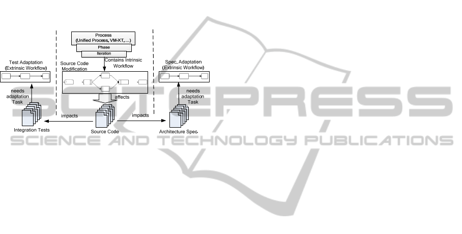
intrinsic workflows, we refer to Figure 1.
Figure 1: Intrinsic and Extrinsic Workflows.
Our previous work has described a holistic
framework that applies semantic web (SemWeb)
technologies to SE lifecycles (Oberhauser and
Schmidt, 2007) and integrates context-awareness
and PAIS technology (Oberhauser, 2010) to provide
SE process support. (Grambow et al., 2010a) dealt
with explicit modeling and execution support for
extrinsic activities utilized for the automated
treatment of specialized issues in SE projects.
(Grambow et al., 2011) investigated consistency in
the modeling of processes and workflows in SE to
unite abstractly specified processes as well as the
concretely and automatically supported workflows.
Finally, automatic integration of quality aspects into
processes was investigated in (Grambow and
Oberhauser 2010; Grambow et al., 2010b).
To comprehensively support the SE process,
various other aspects should also be considered: The
concrete triggering and orchestration of
collaboration activities is desirable. To enable
configurable collaboration support, various activity
dependencies should be supported. For instance,
direct follow-up actions may be necessary while in
other cases notification to other team members may
suffice. So that extrinsic activities support
traceability and are integrated in the SE process,
they should be associated with appropriate intrinsic
activities. In support of user contextual-awareness,
automated guidance should not only be provided for
the activities in one workflow (horizontal
connections between the activities), but also
vertically, making the hierarchical connections
between processes and workflows explicit.
In this paper, the connection of intrinsic and
extrinsic activities is addressed, featuring a context-
based reasoning process to automatically derive
consequences of activities (e.g., impacts on other
artifacts) and govern follow-up activities.
Additionally, the connection between abstract
processes and concrete workflows is emphasized,
providing this information to the user to support
navigability and process awareness.
The structure of the paper is as follows: the
problems addressed are illustrated in the next
section, followed in Section 3 with a description of
the solution approach. Section 4 shows the
application of our approach to the illustrated
problems. Section 5 addresses the issue of the
additional effort required. Section 6 then discusses
related work, followed by the conclusion.
2 PROBLEM SCENARIO
The issues being addressed will be illustrated using
two problem areas: The (horizontal) connection of
intrinsic and extrinsic activities as well as the
(vertical) connection of abstract and concrete
process regions. Extrinsic workflows often involve
activities triggered by, and thus dependent on,
intrinsic activities. Thus, a coherent modeling and
coordination between extrinsic and intrinsic
activities is needed.
To illustrate these dependencies between
intrinsic and extrinsic activities, a scenario
comprising activities that imply changes to artifacts
(e.g., source code or documentation files) is used.
Generally, many of the activities of intrinsic
workflows involve such changes. Artifact changes,
in turn, often imply certain follow-up actions that are
hitherto coordinated manually. Figure 1 depicts this
scenario for a source code artifact that is part of an
interface component: since the file belongs to an
interface component, the applied changes possibly
not only affect the unit tests of the file, but also other
artifacts such as the architecture specification or
integration tests. These additional activities are
usually neither covered by the SE process nor
governed by workflows; manual coordination can
lead to impacts being forgotten and result in
inconsistencies, e.g., between the source code and
the tests or specifications. Even if not forgotten,
follow-up actions could benefit from automated
governance and support. Furthermore, it can be
ICSOFT 2011 - 6th International Conference on Software and Data Technologies
6
difficult to determine which stakeholder should be
informed about which change and when, especially
considering the dynamic and diverse nature of the
artifact-to-stakeholder relationship and various
information needs.
The second problem regarding process
integration in SE projects is to bridge the gap
between the abstract high-level archetype processes
and the concrete actions and workflows performed
by project participants. Not addressing this challenge
can hinder collaboration due to a lack of situational-
awareness. This occurs especially in multi-team /
multi-project environments where users often switch
between projects. For a person performing a task in
such an environment, it can be beneficial after such
a switch to have information about the project
directly available. That includes information about
the project, phase, iteration, activity deadline, other
activities related to the current activity, and the
persons to be contacted in special situations.
3 SOLUTION APPROACH
This section presents the approach taken to address
the aforementioned issues.
3.1 Concept
The essence of our solution approach is the
combination of an adaptive PAIS with SemWeb
technology. A process management module is used
to model both intrinsic and extrinsic workflows in
an integrated way, while additional information
about hierarchical dependencies and the context are
stored and processed in a SemWeb-based context
management module. To acquire information about
the environment, low-level events that occur during
SE tool usage (e.g., saving a file or changing code)
are extracted and combined to derive higher-level
activities such as creating a unit test. The realization
of the solution approach is the Context-aware
Software Engineering Environment Event-driven
frameworK (CoSEEEK). It is comprised of modules
in a service-based architecture: The Process
Management module orchestrates SE activities for
all project participants. Flexible PAISs support the
coordination of activities according to a predefined
process model as well as dynamic process changes
(e.g., to add, delete, or move activities) in order to
cope with unforeseen situations (Adams et al., 2006;
Dadam and Reichert, 2009; Weber et al., 2009). For
Context Management, SemWeb technology was
chosen due to its many advantages (Gasevic et al.,
2006), especially a vocabulary including logic
statements about the modeled entities and relations
as well as a taxonomy for these entities.
Furthermore, well-structured ontologies also
enhance interoperability between different
applications and agents, fostering knowledge sharing
and reuse as well as enabling automated consistency
checking. Event Extraction primarily utilizes sensors
for collecting contextual state changes in external
elements via events and data associated with various
SE tools. These low-level atomic events and data are
aggregated in the Event Processing module, which
uses complex event processing (CEP) to create high-
level events with contextual semantic value.
The combination of these modules enables
CoSEEEK to automatically manage ad-hoc
dependencies of certain activities in an either active
or passive information distribution fashion. Active
information distribution means that the system
automatically assigns follow-up activities to
responsible persons or teams. Passive information
distribution means that the system provides retrieval
capabilities and only creates notifications for users
to inform them about changes. To enable such
automated information distribution, a system must
be capable of automatically identifying different
areas of interest in a project. Therefore, CoSEEEK
introduces different concepts for logically separating
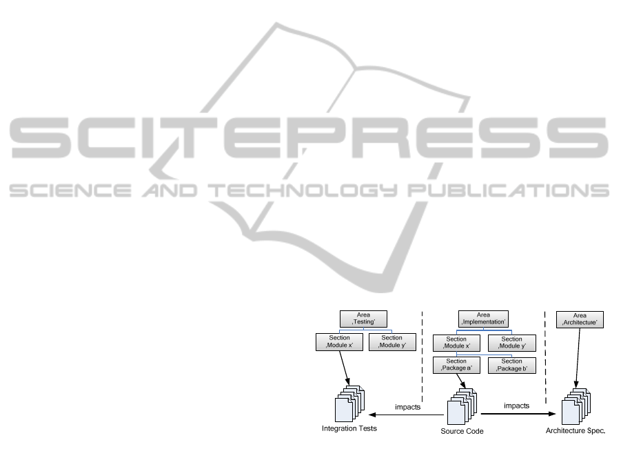
a project as illustrated in Figure 2.
Figure 2: Area / Section Example.
Areas of a project such as ‘Implementation’ or
‘Architecture’ can be explicitly defined and further
segregated into sections. These definitions can be
tailored for projects and automatically supported.
For example, to split up the ‘Implementation’ area,
the structures of the source code can be scanned
creating subsections of the area alongside the
package structure of the source code.
Information distribution comprises a three-
phased approach:
1. Determine projects areas that are affected
by an activity.
2. Determine the concrete target that is affected
within the area.
TOWARDS AUTOMATIC PROCESS-AWARE COORDINATION IN COLLABORATIVE SOFTWARE
ENGINEERING
7
3. Determine the information recipient that is
responsible for the chosen target.
The first step is configurable and can take into
account various facts to determine which areas are
affected. For the aforementioned scenario, such a
configuration can be ‘Search for affected areas in
case of technical issues if an activity implies a
change to an artifact and the artifact is a source code
artifact and belongs to an interface component’.
The second step takes the selected areas and the
target of the applied activity as input. This target can
be a concrete artifact as in the given scenario or a
more abstract section of the project as, e.g., a
module. The concrete target is then determined via
relations of the different sections. An example for
this can be implementation and testing: the testing
(structural or retesting) of a module relates to its
implementation. In the given example, the relation
does not need to be in place for the concretely
processed component, but can also be found if one
exists elsewhere in the hierarchy. If there is no direct
relation from the processed source code artifact, the
system looks for other components the file belongs
to, e.g., the module.
Once the target for the information distribution
or follow-up action is determined, the responsible
persons or teams must be discovered. For example,
if the target of the follow-up action is a source code
file with no direct responsible party defined, the
overlying sections are also taken into account, e.g.,
the encapsulating module. If a team is responsible,
the information is referred to the designated contact
of that team for further distribution.
Finally, CoSEEEK tracks the workflow progress
at different levels of abstraction (concrete
workflows, iterations, phases). Thus, the
collaboration of team members is promoted by
providing them with context information fostering
situational awareness. This is especially useful in
multi-project environments where members switch
between different projects. Hereby a bidirectional
association between the abstract project level, the
process level, and the level where concrete activities
are executed is established.
3.2 Realization
To realize the solution approach, the AristaFlow
BPM Suite (formerly ADEPT2) (Dadam and
Reichert, 2009) was chosen as PAIS technology due
to its correctness-by-construction principle and its
process adaptability features (e.g., robust support for
ad-hoc process changes during runtime). CoSEEEK
makes use of these advanced process change
facilities and integrates them into its framework via
the AristaFlow API. For structuring and accessing
contextual information, the Context Management
module employs an OWL-DL ontology as well as
SWRL (World Wide Web Consortium, 2004) rules
and SPARQL (Prud’hommeaux and Seaborne,
2006) queries. Programmatic access to the ontology
is provided by the Jena API (McBride, 2002) and
reasoning by Pellet (Sirin et al., 2006). For Event
Extraction, Hackystat (Johnson, 2007) was used due
to its Java support and its sensors for various tools
and applications. Events are processed and complex
events generated using Esper. For Data Storage, the
tuple space paradigm (Gelernter, 1985) was
implemented as an XML space based on the eXist
XML database.
To support an abstract process and context
model, an ontology adapting various features and
concepts of the Software Process Engineering
Metamodel (SPEM) (Object Management Group,
2008) was created. Certain SPEM features were
omitted to reduce complexity or because some
aspects are managed extraneous to the ontology in
other CoSEEEK modules.
3.2.1 Automatic Workflow Coordination
To realize automatic workflow coordination, the
system must be aware of the intrinsic activities and
workflows that may cause the need for coordination.
These workflows, which are based on the users’
Assignments and are part of the SE process, are
created within CoSEEEK or imported from external
process management tools (e.g., MicroTool inStep)
in use by an organization. In this paper, OpenUP is
used as a SE process model. Assignments concerning
software development are captured by the ‘Develop
Solution Increment’ workflow in that model and
imply certain activities (called AssignmentActivities
in CoSEEEK) like ‘Implement Solution’ or
‘Implement Tests’. To exemplify the governance of
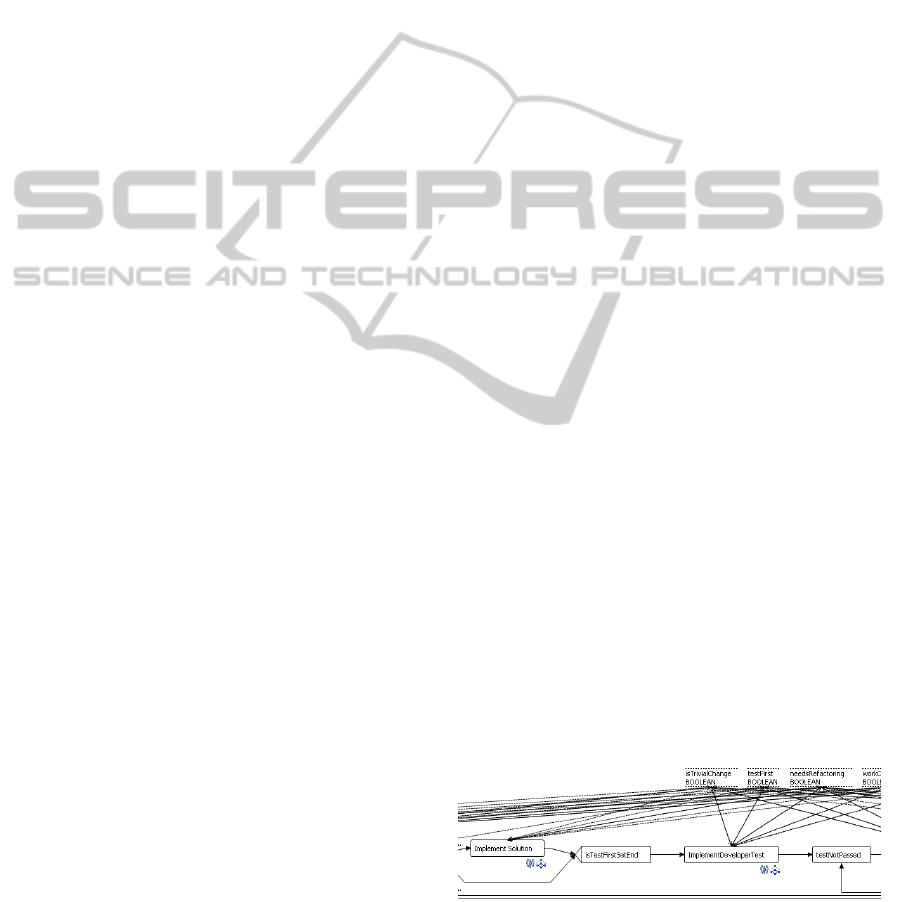
intrinsic workflows, Figure 3 shows a snippet of this
workflow modeled in AristaFlow.
Figure 3: Snippet of an Intrinsic Workflow modeled in
AristaFlow.
CoSEEEK features semantic enhancements of
process management concepts to enable
ICSOFT 2011 - 6th International Conference on Software and Data Technologies
8
comprehensive automated workflow governance. All
workflows are mirrored in the ontology using the
following concepts: The WorkUnitContainer mirrors
a workflow and the WorkUnit mirrors an activity.
The Assignment and AssignmentActivity concepts are
separated, where the Assignment is related to a
WorkUnitContainer and the AssignmentActivity is
related to a WorkUnit as shown in Figure 4. When
an Assignment including the other concepts (relating
WorkUnitContainer, WorkUnits, and Assignment-
Activities) is created or imported, the procedure to
detect possible impacts is invoked. The detection is
based on the AssignmentActivities and their relations
to project components like artifacts. If an impact can
be detected, the trigger for a follow-up action is
stored as part of the AssignmentActivity in the
ontology to be executed after the execution of the
latter. The information on affected project
components is derived from the Assignment (e.g.,
‘Change module X’) and may be coarse-grained at
that point. It can be detailed later when the activity is
executed because at that time the affected
components become known by the system.
Figure 4: Ontology Section used for Navigability.
To enable automated detection of follow-up
actions, different facts have to be modeled in the
ontology:
(1) The project has to be hierarchically split up
into components like areas or modules.
(2) Connections of different relating components
must be established as, e.g., the fact that
testing a module relies on implementing that
module.
(3) Information that can be used to clarify under
which circumstances one area affects another
must exist.
(4) Different components must be classified, as,
e.g., a package in the source code that
realizes the interface of a component.
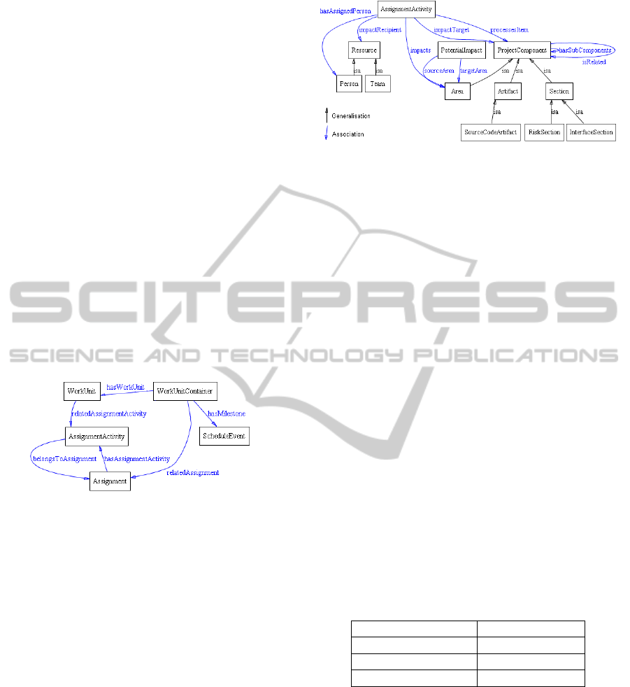
The concepts utilized for modeling these facts are
shown in Figure 5.
The separation of the project into logical
components (1) is done by the ProjectComponent,
which has various subclasses. In Figure 5, Area,
Section, and Artifact are shown.
Figure 5: Ontology Section used for Workflow
Coordination.
An Assignment-Activity that is executed by a
Person processes a certain ProjectComponent. A
ProjectComponent has a responsible Role taken by a
Resource that is a Team or a Person. To enable
custom configurations of the possible impacts of an
activity, different concepts are used: The
PotentialImpact captures potential impacts between
Areas (3) like ‘When a technical change happens to
a component in Area a, this has an impact on Area
b’. Project-Components of different Areas can be
related to each other (2) like ‘Testing of module x
relates to the implementation of module x’. Figure 6
illustrates the PotentialImpact as well as the
relations (curved lines). Many of the concepts also
have asserted subclasses for further classifying them
(4) that are dependent on certain conditions. For
example, if a Section is connected to problems that
were detected by CoSEEEK (e.g., code problems
indicated by static analysis tools), the reasoner
automatically infers that it belongs to the concept
RiskSection. The three steps of the procedure are
realized using the semantic techniques shown in
Table 1.
Table 1: Procedure realization for responsible party
detection.
Detection Steps Realization
1. Impact Areas SWRL Rule 1
2. Concrete target SWRL Rule 2
3. Responsible person SPARQL Query 1
A concrete example for all steps is given in
Section 4 along the problems defined in Section 2.
As aforementioned, the presented approach features
concrete follow-up activities as well as notifications
about the changes. Since both procedures are very
similar and due to space limitation only the more
complicated case of follow-up activities is explained
here. The first step, the detection of impacts on other
areas is realized via SWRL Rule 1 that can be
custom defined to match the needs of the project or
company. Therefore, the development of a GUI for
TOWARDS AUTOMATIC PROCESS-AWARE COORDINATION IN COLLABORATIVE SOFTWARE
ENGINEERING
9

easy definition of rules is planned. The rule
establishes a connection called ‘impacts’ between
the AssignmentActivity and the affected Areas. An
example for such a starting rule is shown in Section
4.The established connection is utilized in the
SWRL Rule 2 that, establishes a connection called
‘impactTarget’ between the Assignment-Activity and
a ProjectComponent as shown in the following:
SWRL_Rule_2:
impacts(?activity, ?area) ∧
allInferredSuperComponents
(?targetComponent, ?area) ∧
processesItem(?activity,
?sourceComponent) ∧ isRelated(
?sourceComponent,?targetComponent)
→ impactTarget(?activity,
?targetComponent)
The rule looks for a component in the target area
that is related to the component processed by the
activity. That component is taken as the concrete
target. The rule makes use of transitivity in the
defined ontology structure: The hierarchical
connections between the different Project-
Components are defined transitively and the
reasoner is used to infer all sub or super components
that are stored in separate relations (as used in the
rule by the relation ‘allInferredSuperComponents’).
Via transitivity, it is also possible to not only look
for relations of the currently processed component,
but also for all components above, creating multiple
impact targets with another SWRL rule.
When the concrete target is determined, the
responsible Resource is queried via SPARQL Query
1 and stored in the AssignmentActivity. Due to space
limitations, the SPARQL query is omitted here.
After the execution of an AssignmentActivity
with a configured follow-up action, the Context
Module writes a “Process Start Event” (containing
the relating user ID and information about the task
relating to it) to the XML Space. The event is then
automatically received by the Process Module,
which starts the appropriate workflow with the tasks
for the appropriate Person. When an activity
becomes activated during workflow execution, a
corresponding task becomes available for the related
Person. The task information is encapsulated in an
event in the XML Space that is automatically
retrieved by a PHP-based web application that
displays the task list of the respective Person in a
web browser or within an IDE such as Eclipse (see
Figure 7).
3.2.2 Navigability and Situational
Awareness
To provide context information for situational
awareness, a set of queries to the ontology was
defined. Figure 4 depicts the corresponding subset of
the ontology. It shows the concrete classes for
modeling the development process. All work that is
done within a Project is modeled via the WorkUnit,
WorkUnitContainer, Assignment, and Assignment-
Activity. These concepts are used for modeling the
abstract process regions (e.g., projects, iterations) as
well as the concrete regions (e.g., workflows,
activities) and provide a connection between them.
WorkUnitContainers can have Milestones and
AssignmentActivities can have relations to
ProjectComponents as also shown in Figure 5.
By utilizing the associations of these classes,
various queries become possible. For example, in an
agile project that is separated into phases and
iterations, one can query the milestone of the project
phase in which the current iteration takes place or
query the project to which the actual workflow
belongs. Navigability is not only possible from the
concrete to the abstract process regions, but also in
the opposite direction, featuring queries such as
retrieving all active activities for a project phase.
The information from the ontology is provided in a
standardized way using SPARQL.
For internal usage, CoSEEEK encapsulates
information in events stored in the XML Space for
inter-module access. For external applications, in
turn, a web service interface provides access to all
queries. As a direct benefit to users, navigability is
integrated into the CoSEEEK GUI, showing all
abstract concepts to which the currently processed
activity belongs.
4 APPLICATION EXAMPLE
For validation of our solution approach, the scenario
from Section 2 is used. Prior work investigated the
practicality of technical aspects such as performance
with regard to CoSEEEK realization elements
(Grambow et al., 2010a, 2010b).
As illustrated in Section 2, the modification of a
source code artifact that belongs to the interface of a
component is the target. This change can require
adapting integration tests or architecture documents.
Dependent adaptations usually do not appear in the
workflows belonging to SE processes and are thus
extrinsic workflows. The given example illustrates
the case for the follow-up actions regarding the tests
ICSOFT 2011 - 6th International Conference on Software and Data Technologies
10
as shown in Figure 6.
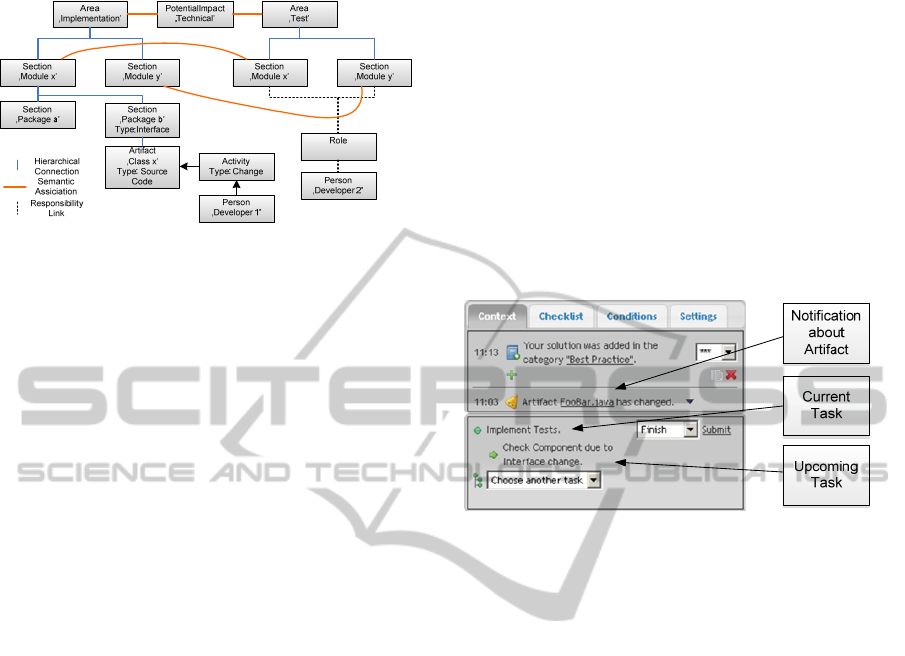
Figure 6: Application of CoSEEEK to the problem
scenario.
Figure 6 shows two defined project areas
‘Implementation’ and ‘Test’. There is a
PotentialImpact configured for relating technical
issues from ‘Implementation’ to ‘Test’. For the
implementation area, there are different modules
with different packages. Modules x and y also
appear in the test area and relate to the counterparts
in the implementation area as indicated by the
curved lines. Developer 2 is responsible for the tests
of Modules x and y. Assume now that Developer 1
changes a class belonging to Package b, indicated by
the change activity. The first step of the detection
procedure for follow-up actions in this example is
done by SWRL Rule 1 that takes into account the
PotentialImpact, the fact that Package b is an
interface component, the type of the activity, and the
type of artifact that was processed.
SWRL_Rule_1:
sourceArea(?impact, ?source)
∧
targetArea(?impact, ?target)
∧
allInferredSubComponents(?source,
?subComp)
∧
InterfaceSection(?subComp)
∧
allInferredSubComponents(?subComp,
?artifact)
∧
processesItem(?activity, ?artifact)
∧
ChangeActivity(?activity)
∧
SourceCodeArtifact(?artifact)
→ impacts(?activity, ?target)
The rule determines that the activity affects the
test area. With this information the second step can
be performed. As mentioned in Section 3.2.1, two
different SWRL rules can be used for this. One only
looks for an impact target relating to the processed
component, while the other also takes into account
all overlaying components. In this example, the
second rule detects an impact target: in the
‘Implementation’ Area, the source code file belongs
to Package b that belongs to Module x, which has a
relation to the ‘Module x’ Section in the Area ‘Test’.
After determining the concrete target, the
recipient of the follow-up activity can be queried via
SPARQL. In the given case, it is Developer 2.
The information about the component, the kind
of change applied to it, and the user ID of the
responsible person are forwarded via an event to the
Process Management module, which starts a
workflow to govern the desired activities for the
respective user. This workflow can be based on a
predefined workflow template or be custom built
from a problem-oriented declarative definition as
described in (Grambow et al., 2010a). When a task
of that workflow becomes available to a user, an
event is automatically distributed to CoSEEEK’s
web GUI shown in Figure 7.
Figure 7: CoSEEEK Web GUI.
All tasks are shown at the bottom of the GUI. In
order to avoid subjecting a user to information
overload, only the current task and the next
upcoming task proposed by the system are shown.
The user may change the selection of the next
upcoming task via a dropdown list. In this example,
the current task is “Implement Tests” from an
intrinsic workflow, while the next upcoming task is
“Check Component due to Interface Change” from
an extrinsic workflow. The upper part of the GUI
contains information provided by the framework.
Among other things, it can be used to display
additional task information and notifications about
components for which change notification is
configured. This example shows the notification
about the change of an artifact.
Automatic coordination, however, is not always
necessary and not feasible in all cases. In other
scenarios (see Section 2), team members could use
context information to foster collaboration. For
example, in an environment where persons take part
in multiple projects concurrently, it might be helpful
to retrieve contextual information when switching
projects. This option is provided by CoSEEEK,
which shows all upper processes to which the
current activity belongs.
In summary, the resolution provides
collaboration capabilities via coordination of
TOWARDS AUTOMATIC PROCESS-AWARE COORDINATION IN COLLABORATIVE SOFTWARE
ENGINEERING
11

extrinsic and intrinsic workflows in a PAIS and the
availability and use of context information via
SemWeb technology. Activities that are often
omitted and not modeled in PCSEEs are explicitly
modeled and automatically coordinated via
CoSEEEK. Additional support is provided for
software engineers working in multi-project
environments by making navigability information
available and fostering situational awareness.
5 MODELING EFFORT
Additional modeling effort is imposed by the
approach. The processes are modeled not only in the
PAIS but also in the ontology. Configuration is
required for how various follow-up actions should
be treated. To keep the effort reasonable, some
default functions and definitions are provided in the
framework. The semantic enhancements to Process
Management (WorkUnitContainers and WorkUnits)
are generated automatically from the workflow
templates of the Process Management module. To
gain an awareness of project artifacts, scans are
conducted on specified folders. Since the system is
aware of SE tools via sensors, it becomes aware of
all processed and new artifacts, and the information
is acquired on the fly. An initial set of
ProjectComponents is provided and the structure of
certain Areas can be imported, e.g., from a folder
structure or a source code package structure.
Examples include the Areas ‘Implementation’ and
‘Test’: the system can automatically read the
package structure and thus import references to all
artifacts into the ontology that are hierarchically
organized under various Sections that are created
from the different packages in the source code. The
names of the packages can be automatically matched
to those to which they may relate. For instance,
relations between ‘Test’ packages and
‘Implementation’ packages can be automatically
established.
6 RELATED WORK
With regard to PCSEEs, (Adams et al., 2006)
describe SOA-based extensible and self-contained
sub-processes that are aligned to each task. A
dynamic runtime selection is made depending on the
context of the particular work instance. OPEN
(Henderson-Sellers, 2002) is a CORBA-based
PCSEE that addressed business, quality, model, and
reuse issues. DiME (Koenig, 2003) provides a
proprietary, integrated, collaborative environment
for managing product definition, development, and
delivery processes and information. CASDE (Jiang
et al., 2007) and CooLDev (Lewandowski and
Bourguin, 2007) utilize activity theory for building
an environment supporting collaborative work.
CASDE features a role-based awareness module
managing mutual awareness of different roles.
CooLDev is a plug-in for the Eclipse IDE that
manages activities performed with other plug-ins in
the context of global cooperative activities. CAISE
(Cook et al., 2004) is a collaborative SE framework
with the ability to integrate SE tools. CAISE
supports the development of new SE tools based on
collaboration patterns.
An industry approach for collaborative
development is provided by the IBM Jazz / Rational
Team Concert products (IBM Jazz, 2011). Jazz
offers an infrastructure for distributed development
including the technical basis for integration of
various clients as well as data and services. It
enables comprehensive project, bug, and
configuration management as well as event
notifications, traceability, and other software
development related tasks. Team Concert is a
collaborative software development environment
built on Jazz technology utilizing its capabilities to
provide an integrated solution for software
configuration management, work item management,
and build management with additional features like
customizable dashboards, milestone tracking, or
process templates for common processes.
In contrast, CoSEEEK offers a combination of
features not found in the aforementioned
approaches: workflow guidance is not only offered
for activities contained in development processes
(intrinsic), but also for extrinsic activities, which are
not explicitly modeled within those processes. The
holistic combination of all project areas in
conjunction with SemWeb technology also enables
the framework to provide intelligent decisions and
thus a higher level of automation. The tight
integration of PAIS technology with context
knowledge not only enables the distribution of
information, but also the automated support and
governance of activities in adapted workflows.
Modeling SE processes in SemWeb technologies
can enhance reuse and leverage available tooling, as
shown by (Liao, 2005). (Soydan and Kokar, 2006)
used an ontology for CMMI-SW assessments, and
(Calero et al., 2006) used ontologies for the
Software Engineering Body of Knowledge
(SWEBOK). CoSEEEK leverages SemWeb usage
for real-time contextual-awareness in SEEs to
ICSOFT 2011 - 6th International Conference on Software and Data Technologies
12

improve SE workflows and collaboration and for
supporting navigability and situational-awareness.
The main differentiation criterion to other
approaches that utilize ontologies for collaboration
is the holistic integration of all project areas to
foster synergies, and in having collaboration not be
the sole focus of the framework (e.g., software
quality assurance is adaptively integrated as
described in (Grambow et al., 2010b)). Other
approaches have collaboration via ontologies as their
focus, as shown by (Wang et al., 2007) and (Yao et
al., 2007). Yao et al. present a workflow-centric
collaboration system whereby the main component
is an ontology repository with ontologies of different
abstraction levels. The process model is based on
enhanced Petri nets and thus lacks dynamic
adaptability. Wang et al. present an Ontology for
Contextual Collaborative Applications (OCCA) that
provides a generic semantic model specialized for
distributed, heterogeneous, and context-aware
environments. In contrast to these approaches,
CoSEEEK utilizes querying and reasoning
capabilities over an ontology and integrates these
with process management to support automated
dynamic process governance.
7 CONCLUSIONS
The high degree of dynamic collaboration in SE
raises challenges for automated support of process
awareness and guidance in SEEs. Currently, SEEs
lack contextual information and integration,
especially with regard to adaptive collaboration and
workflows. The presented CoSEEEK approach
extends adaptive PAIS with semantic web
technologies and advanced event processing
techniques. CoSEEEK explicitly models and
manages intrinsic as well as extrinsic activities.
These are coordinated, and information and activity
distribution can be individually configured. A
dynamic information distribution strategy enables
related components to be associated even if no direct
relations between the source component and the
target component exist. The responsible person for a
component can also be determined if no direct
responsibility is defined. The procedure neither
requires rigidly predefined information channels nor
does it rely on comprehensive and fine-grained
predefined information on relating artifacts or
responsible persons. The configuration effort to
enable automated coordination is reduced by the
ability to automatically import needed information
and via the inference and reasoning capabilities.
Extrinsic activities that have hitherto typically
been excluded from modeling are now guided by
workflows. These capabilities enable the integration
of general process models with concrete activities
even if they are extrinsic to a particular SE process.
As collaborations become more complex, support
for situational awareness and navigability becomes
vital. Manual process navigability through
abstraction levels within the collaboration is enabled
with live querying capabilities on the contextual
information in the ontology.
The presented scenario demonstrated a situation
where improved coordination and situational
awareness were supported while providing process
guidance and navigability for collaborating software
engineers, enhancing process quality.
Automated support for coordinated collaborative
software engineering, with its human interactions
and continuously changing tool and process
environment, will remain a challenge. Further
research potential lies in the aggregation and
utilization of available contextual information to
increase process effectiveness and efficiency. Future
work will investigate industrial usage in production
environments with our project partners. For
efficiency, a planned new feature will aggregate
related tasks and, when a predefined threshold is
reached, trigger a workflow instance with the
cumulated task information. More complex task
treatments can also be designated: e.g., in an agile
project, emergent uncompleted tasks can be
collected and stored in a backlog to inform team
members at the beginning of the next iteration. A
GUI for assisted definition of the SWRL rules for
the first step of the procedure is also planned.
ACKNOWLEDGEMENTS
The authors wish to acknowledge Stefan Lorenz for
his assistance with the implementation. This work
was sponsored by the BMBF (Federal Ministry of
Education and Research) of the Federal Republic of
Germany under Contract No. 17N4809.
REFERENCES
Adams, M., ter Hofstede, A.H. M., Edmond, D., van der
Aalst, W. M. P., 2006. Worklets: A Service-Oriented
Implementation of Dynamic Flexibility in Workflows.
In: LNCS, 4275, 291-308. Springer.
Calero, C., Ruiz, F., Piattini, M. (Eds.), 2006. Ontologies
for Software Engineering and Software Technology,
Springer.
TOWARDS AUTOMATIC PROCESS-AWARE COORDINATION IN COLLABORATIVE SOFTWARE
ENGINEERING
13

Cook, C., Churcher, N., Irwin, W., 2004. Towards
Synchronous Collaborative Software Engineering. In:
Proc. 11th Asia-Pacific Software Eng. Conf., 230-239.
Dadam, P., Reichert, M., 2009. The ADEPT project: a
decade of research and development for robust and
flexible process support - challenges and
achievements. Computer Science - Research and
Development, 23(2), 81-97.
Gasevic, D., Djuric, D., Devedzic, V., 2006. Model driven
Architecture and Ontology Development, Springer.
Gelernter, D., 1985. Generative communication in Linda,
ACM Transactions on Programming Languages and
Systems, 7(1), 80-112.
Grambow, G., Oberhauser, R., 2010. Towards Automated
Context-Aware Selection of Software Quality
Measures. In: Proc. of the Fifth Intl. Conf. on Software
Engineering Advances (ICSEA 2010), IEEE Computer
Society Press, 347-352.
Grambow, G., Oberhauser, R., Reichert, M., 2010a.
Semantic Workflow Adaption in Support of Workflow
Diversity. In: Proc. 4th Int’l Conf. on Advances in
Semantic Processing (SEMAPRO 2010), Xpert
Publishing Services, 158-165.
Grambow, G., Oberhauser, R., Reichert, M., 2010b.
Employing Semantically Driven Adaptation for
Amalgamating Software Quality Assurance with
Process Management. In: Proc 2nd Int’l. Conf. on
Adaptive and Self-adaptive Systems and Applications
(ADAPTIVE 2010), Xpert Publishing Services, 58-67.
Grambow, G., Oberhauser, R., Reichert, M., 2011.
Towards a Workflow Language for Software
Engineering. In: Proc 10
th
IASTED Int’l. Conf. on
Software Engineering, ACTA Press.
Gruhn, V., 2002. Process-Centered Software Engineering
Environments: A Brief History and Future Challenges.
Annals of Software Engineering, 14(1-4), 363-382.
Henderson-Sellers, B., 2002. Process Metamodelling and
Process Construction: Examples Using the OPEN
Process Framework (OPF). Annals of Software
Engineering, 14(1-4), 341-362.
IBM Jazz, 2011. http://www.jazz.net.
Jiang, T., Ying, J., Wu, M., 2007. CASDE: An
Environment for Collaborative Software
Development. LNCS, 4402, 367-376. Springer.
Johnson, P.M., 2007. Requirement and Design Trade-offs
in Hackystat: An In-Process Software Engineering
Measurement and Analysis System. In: Proc. of 1st
Int. Symposium on Empirical Software Engineering
and Measurement, IEEE Computer Society Press.
Koenig, S., 2003. Integrated Process and Knowledge
Management for Product Definition, Development and
Delivery. In: Proc. of the IEEE Int. Conf. on Software-
Science, Technology & Engineering (SWSTE), IEEE
Computer Society Press.
Liao, L., Qu, Y., Leung, H., 2005. A software process
ontology and its application. In: ISWC2005 Workshop
on Semantic Web Enabled Software Engineering.
Lewandowski, A., Bourguin, G., 2007. Enhancing Support
for Collaboration in Software Development
Environments, LNCS, 4402, 160-169. Springer.
McBride, B., 2002. Jena: a semantic web toolkit, Internet
Computing, Nov 2002, 55-59.
Mutschler, B., Reichert, M., Bumiller, J., 2008.
Unleashing the Effectiveness of Process-oriented
Information Systems: Problem Analysis, Critical
Success Factors, and Implications. IEEE Transactions
on Systems, Man, and Cybernetics (Part C), 38 (3):
280-291.
Oberhauser, R., Schmidt, R., 2007. Towards a Holistic
Integration of Software Lifecycle Processes using the
Semantic Web. Proc. 2nd Int. Conf. on Softw. and
Data Technologies (ICSOFT 2007), 137-144.
Oberhauser, R., 2010. Leveraging Semantic Web
Computing for Context-Aware Software Engineering
Environments. In: Semantic Web, Gang Wu (Ed.), In-
Tech, Austria.
Object Management Group, 2008. Software & Systems
Process Engineering Meta-Model Specification 2.0.
OpenUP, 2011. http://epf.eclipse.org/wikis/openup/
Prud’hommeaux, E., Seaborne, A., 2006. SPARQL Query
Language for RDF, W3C WD 4.
Rausch, A., Bartelt, C., Ternité, T., Kuhrmann, M., 2005.
The V-Modell XT Applied - Model-Driven and
Document-Centric Development. The 3rd World
Congress for Software Quality.
Sirin, E., Parsia, B., Grau, B.C., Kalyanpur, A., Katz, Y.,
2006. Pellet: A practical OWL-DL Reasoner. Journal
of Web Semantics.
Soydan, G.H. and Kokar, M., 2006. An OWL Ontology
for Representing the CMMI-SW Model. Proc. of 2nd
Int. Workshop on Semantic Web Enabled Software
Engineering.
Wang, G., Jiang, J. and Shi, M., 2007. Modeling Contexts
in Collaborative Environment: A New Approach.
LNCS, 4402, 23-32. Springer.
Weber, B., Sadiq, S. and Reichert, M., 2009. Beyond
Rigidity - Dynamic Process Lifecycle Support: A
Survey on Dynamic Changes in Process-aware
Information Systems. Computer Science - Research
and Development, 23 (2). pp. 47-65. ISSN 1865-2034.
World Wide Web Consortium, 2004. SWRL: A Semantic
Web Rule Language Combining OWL and RuleML.
W3C Member Submission
Yao, Z.,Liu, S., Han, L., Ramana Reddy, et al., 2007. An
Ontology Based Workflow Centric Collaboration
System. LNCS, 4402, 689-698. Springer.
ICSOFT 2011 - 6th International Conference on Software and Data Technologies
14
