
TOWARDS OPTIMAL REVOCATION AND TRACING SCHEMES
The Power of the Ternary Tree
Kazuhide Fukushima
∗1
, Shinsaku Kiyomoto
1
, Yutaka Miyake
1
and Kouichi Sakurai
∗2,3
1
KDDI R&D Laboratories Inc., Saitama, 356–8502, Japan
2
Faculity of Information Science and Electrical Engineering, Kyushu University, Fukuoka, 819–0395, Japan
3
Institute of Systems, Information Technologies and Nanotechnologies, Fukuoka, 814–0001, Japan
Keywords:
Broadcast encryption, Subset difference method, Traitor tracing, Ternary tree.
Abstract:
Digital content distribution services require that 1) only valid user devices that has a valid key can decrypt the
broadcasting content, 2) the keys can no longer be used to decrypt the content, if keys in a device are revealed,
and 3) invalid users who illegally use keys in a device can be identified. This paper proposes a broadcast
encryption scheme with traitor tracing based on the ternary tree structure. We design a new cover-finding algo-
rithm and label assignment algorithm in order to achieve a coalition-resistant revocation and tracing schemes.
In our scheme, the number of labels stored in a client device can be reduced by about 20.4 percent and the
average header length by up to 15.0 percent in the case where the total number of devices is 65,536. The effi-
ciency of the traitor tracing is the same as the complete subtree method, and its computational cost imposed on
a client device stays within O(logn). Our scheme is an improvement of the complete subtree and difference
subset methods.
1 INTRODUCTION
1.1 Background
Digital content broadcasting services have become
major in the 3G and beyond 3G mobile market due
to advancing of its communication speed. Unautho-
rized use of the digital content has been a major issue
for the mobile services. In digital content distribution,
properties should satisfy the following three require-
ments: 1) only valid user devices that has a valid key
can decrypt the broadcasting content, 2) the keys can
no longer be used to decrypt the content, if keys in a
device are revealed, and 3) invalid users who illegally
use keys in a device can be identified. A broadcast
encryption scheme with a traitor tracing algorithm is
an essential technique to realize these requirements.
∗
The first and forth authors are partially supported by
Strategic Japanese-Indian Cooperative Programme on Mul-
tidisciplinary Research Field, which combines Informa-
tion and Communications Technology with Other Fields by
Japan Science and Technology Agency and Department of
Science and Technology of the Government of India, en-
titled “Analysis of Cryptographic Algorithms and Evalua-
tion on Enhancing Network Security Based on Mathemati-
cal Science”.
1.2 Previous Work
Broadcast Encryption Scheme. The first scheme
is proposed by Berkovits (Berkovits, 1991). Fiat et
al. (Fiat and Naor, 1994) formalized the basic def-
inition of a broadcast encryption scheme. Naor et
al. (Naor et al., 2001) proposed the complete sub-
tree method (the CS method). This scheme uses a
tree and devices are assigned to the leaf nodes of the
tree. Valid devices are covered by complete subtrees
and a key to encrypt the session key is assigned to
each subtree. There is one problem associated with
the CS method in that the header length increases in
proportion to the number of revoked devices. The av-
erage header length is given by O(rlog(n/r)) for the
number of total devices n, the number of revoked de-
vices r. The subset difference method (SD method)
is proposed by Naor et al. (Naor et al., 2001). This
method uses a binary tree to assign labels to devices.
A valid device can derive the key to decrypt the mes-
sage using its labels. The valid devices are covered
by subtrees with another subtree covering revoked de-
vices. A key to encrypt the session key is assigned to
each subtree. The header lengths in the average and
worst case scenarios are given by 2rlog2 and 2r− 1,
and each device stores ((logn)
2
/2 + logn/2 + 1) la-
37
Fukushima K., Kiyomoto S., Miyake Y. and Sakurai K..
TOWARDS OPTIMAL REVOCATION AND TRACING SCHEMES - The Power of the Ternary Tree.
DOI: 10.5220/0003447100370049
In Proceedings of the International Conference on Security and Cryptography (SECRYPT-2011), pages 37-49
ISBN: 978-989-8425-71-3
Copyright
c
2011 SCITEPRESS (Science and Technology Publications, Lda.)

bels. Many improvements to these SD methods have
been proposed. Halevy-Shamir (Halevy and Shamir,
2002), Goodrich et al. (Goodrich et al., 2004), Jho
et al. (Jho et al., 2005), Hwang et al. (Hwang et al.,
2005) and Attrapadung-Imai (Attrapadung and Imai,
2007) proposed schemes based on a pseudo-random
number generator. Asano (Asano, 2002), Attra-
padung et al. (Attrapadung et al., 2003) and Gentry-
Ramzan (Gentry and Ramzan, 2004) proposed a
scheme based on the RSA cryptosystem. Jho et
al.’s scheme reduces the header length to r/c but in-
creases the storage size in devices to O(n
c
) where c
is constant. Other schemes reduce the storage size to
less than O((logn)
2
) but increase the average header
length to greater than 2rlog2. Boneh et al. (Boneh
et al., 2005) proposed a scheme based on pairing in
which the header length and storage size do not de-
pend on r; however, this scheme imposes a heavy
computational cost: O(n) on devices.
Group key-management schemes based on the
ternary tree have been proposed (Wang et al., 2006;
Graham et al., 2007; Tripathi and Biswas, 2009). The
CS method can reduce the storage size and tracing
cost by using the ternary tree instead of the binary
tree. However, the SD method cannot protect against
coalition attacks if it is straightforwardly extended
to the ternary tree. The construction of a coalition-
resistant ternary SD method had been an open prob-
lem and we showed a possible solution (Fukushima
et al., 2008).
Traitor Tracing Scheme. Chor et al. (Chor et al.,
1994) proposed the first scheme based on combina-
torics. This scheme requires O(k
4
logn) header length
and O(k
2
logn) storage size where k is the allowable
number of collaborative traitors. Their other scheme
is probabilistic one that requires O(k
2
log(n/p))
header length and O(klog(n/p)) storage size. This
scheme can prevent up to k collaborative traitors from
producing a pirated decoder with probability 1 − p.
Kurosawa-Desmedt (Kurosawa and Desmedt, 1998)
and Boneh-Franklin (Boneh and Franklin, 1999) pro-
posed schemes based on number theory. Then, Kuro-
sawa and Yoshida (Kurosawa and Yoshida, 2002)
showed that these schemes are identical. Chabanne et
al. (Chabanne et al., 2005) and Boneh et al. (Boneh
et al., 2006) proposed a scheme based on bilinear
maps. The schemes based on number theory and
bilinear maps are efficient in terms of the commu-
nication overheads and the required storage size of
devices; however, they impose heavy computational
costs on devices.
1.3 Our Contribution
There exist many improved versions of the CS and
SD method providing a traitor tracing. However, no
method provide efficient traitor tracing using a feasi-
ble header length. The CS method by Naor et al. pro-
vides an efficient tracing with (t logn/log2) compu-
tational overhead, but the header length is rlog(n/r),
where t is the number of traitors. Their SD method
reduces the header length to 2rlog2; however, the
traitor tracing requires (t logn/log(3/2)) computa-
tion.
This paper proposes a coalition-resistant broad-
cast encryption scheme; its header length is re-
duced to 3rlog2 and the traitor tracing requires
(t logn/ log2) computation that is the same as the
computational cost of the CS method. The simula-
tion results show that the proposed method reduces
the average header length by up to 15.0 percent of
the SD method. However, straightforward optimiza-
tions do not work due to the lack of the resistance
against coalition attacks; thus, we need new algo-
rithms. We design a new cover-finding algorithm, la-
bel assignment algorithm and encryption algorithm
in order to achieve a coalition-resistant revocation
scheme, and then we evaluate the efficiency of the
proposed scheme and prove it is secure against coali-
tion attacks.
The rest of the paper is organized as follows:
Section 2 provides the preliminary. We propose the
ternary SD (3SD) method in Sect. 3 and analyze its
security and efficiency in Sect. 4. Section 5 discusses
the comparison with existing schemes and further ex-
tension of our scheme and we conclude our paper in
Sect. 6.
2 PRELIMINARY
Let N be the set of all of the devices, R(⊂ N) be the
set of revoked devices, and |N| = n, |R| = r. Broad-
cast encryption schemes enable the content distribu-
tion center to transmit message M to all devices such
that any valid devices in N\R can decrypt the mes-
sage, but none of the coalitions of revoked devices
can decrypt it. Keys (or labels to derive keys) are pre-
installed on each device and never updated.
The proposed scheme consists of 1) a label assign-
ment algorithm, 2) a cover-finding algorithm, 3) an
encryption algorithm, 4) a decryption algorithm, and
5) a tracing algorithm.
Label Assignment Algorithm. (by the content dis-
tribution center)
SECRYPT 2011 - International Conference on Security and Cryptography
38

Assign labels to each device. The labels are used
to derive a key to decrypt the session key.
Cover-Finding Algorithm. (by the content distribu-
tion center)
Find a family of disjoint subsets {S
1
,S
2
,.. .,S
w
}
such that ∪
w
t=1
S
t
= N\R.
Encryption Algorithm. (by the content distribution
center)
Derive keys L
1
, ..., L
w
to disjoint subsets
{S
1
,S
2
,.. .,S
w
} output by the cover-finding algo-
rithm. Then, encrypt message M with session key
K and encrypt K with keys L
1
, ... , L
w
.
Decryption Algorithm. (by each device d ∈ N\R)
Find subset S
t
to which d belongs. Then, derive
key L
t
to decrypt K and obtain M.
Tracing Algorithm. (by the content distribution cen-
ter)
Find traitors who produced a pirated decoder and
revoke them.
3 PROPOSED SCHEME
We propose a coalition-resistant ternary subset differ-
ence (3SD) method. The proposed scheme can reduce
the communication cost and storage size in devices,
and provide efficient traitor tracing. The 3SD method
can be implemented using encryption functions and
one-way functions; that is, the required primitives are
the same as the SD method.
3.1 Primitives
The 3SD method uses the following primitives;
• A symmetric key encryption function F
K
:
{0,1}
∗
→ {0,1}
∗
to encrypt message M.
• A symmetric key encryption function E
L
:
{0,1}
λ
→ {0,1}
λ
to encrypt session key K.
• One-way functions with pre-image resistance f
lbl
,
f
l ft
, f
cnt
, f
rgt
and f
kgf
: {0,1}
λ
→ {0,1}
λ
. These
one-way functions have to be pairwise distinct.
Note that one-way functions F
1
and F
2
are pair-
wise distinct (Shin et al., 2005) if there is no prob-
abilistic polynomial time adversary that calculates
F
2
(x
1
) from given F
1
(x
1
), or F
1
(x
2
) from given
F
2
(x
2
), for any x
1
,x
2
∈ {0,1}
λ
.
2
f
l ft
, f
cnt
, f
rgt
2
Naor et al. (Naor et al., 2001) constructed three
functions using a pseudo random function G : {0,1}
∗
→
{0,1}
3λ
. In the SD method, they used G
L
(S), G
M
(S), and
G
R
(S) which are the first, second, and third λ bits of G(S),
respectively. We can construct the five functions f
lbl
, f
l ft
,
i
j1
i
j1 j2
D
i
D
j1
D
i
D
j1
D
j2
D
i,j1
=D D
j1
D
i,j1 j2
=D D
j1
D
j2
)
Figure 1: Subsets in 3SD method.
and f
lbl
are used to derive a label l(u,w) from
a label l(u,v) or transformed label f
lbl
(l(u, v)),
where node w is a child of node v. l(u, w) =
f
l ft
( f
lbl
(l(u, v))) holds for any u, v and w such
that w is the left child of v. Similarly, l(u,w) =
f
cnt
( f
lbl
(l(u, v))) or l(u,w) = f
rgt
( f
lbl
(l(u, v)))
holds if w is the center or right child of v. f
kgf
is used to derive a key from a label.
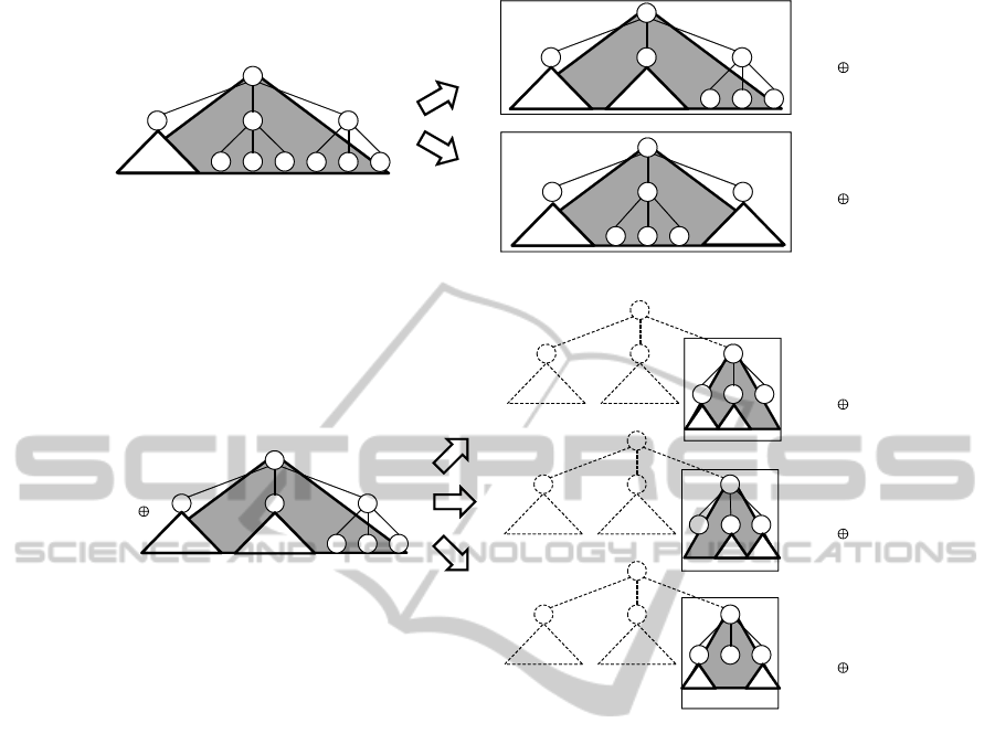
We define the subsets used in the 3SD method.
Then, detailed descriptions of each algorithm is pro-
vided in Sect. 3.3.
3.2 Subsets
In the 3SD method, all the devices in N\R are covered
by the collection of disjoint subsets S
1
, ..., S
w
. Each
subset S
t
is in the form of D
i
\D
j
1
or D
i
\(D
j
1
∪ D
j
2
).
The former is used in the SD method and denoted by
D
i, j
1
. The latter is a characteristic subset in the 3SD
method and denoted by D
i, j
1
⊕ j
2
. In this subset, all of
the devices in D
j
1
and D
j
2
are revoked. The nodes
j
1
and j
2
must be siblings and the descendants of i.
Figure 1 shows these two subsets.
3.3 Revocation Scheme
We describe the detail of the label assigned algorithm,
encryption algorithm and decryption algorithm. The
encryption algorithm takes the set of revoked devices
as input, and the revoked devices cannot decrypt mes-
sages. Thus, these algorithms provide a revocation
mechanism.
3.3.1 Label Assignment Algorithm
This algorithm is executed in the content distribution
center;
f
cnt
, f
rgt
, and f
kg f
based on another pseudo random func-
tion G
′
: {0,1}
∗
→ {0,1}
5λ
. Let G
′
i
(S) be i-th λ bits of
G
′
(S); then, we have f
lbl
(S) = G
′
1
(S), f
l ft
(S) = G
′
2
(S),
f
cnt
(S) = G
′
3
(S), f
rgt
(S) = G
′
4
(S), and f
kg f
(S) = G
′
5
(S).
TOWARDS OPTIMAL REVOCATION AND TRACING SCHEMES - The Power of the Ternary Tree
39

Step 1. Construct a ternary tree to manage devices.
These devices are assigned to leaf nodes of the
tree.
Step 2. Generate random initial labels with λ bits for
all of the nodes except for the leaf nodes in the
tree. Let the initial label for node u be l(u,u). All
of the other labels required in this scheme are de-
rived from these initial labels using one-way func-
tions f
l ft
, f
cnt
, f
rgt
and f
lbl
. Label l(u,w) can be
derived as f
l ft
( f
lbl
(l(u, v))), f
cnt
( f
lbl
(l(u, v))), or
f
rgt
( f
lbl
(l(u, v))) when w is the left, center or right
child of v, respectively.
Step 3. Assign labels and transformed labels to de-
vices. The set Label(u) that the device at the node
u has is given by
Label(u) ={ f
lbl
(l(v,w))|v ∈ Path(u), w ∈ LN(u)}
∪ {l(v,w)|v ∈ Path(u), w ∈ RN(u)}
∪ {l(all)}. (1)
Path(u) is the set of nodes that are on the path
from the root node to u. LN(u) denotes the set
of nodes that hang on the left of the Path(u). If
Path(u) contains the leftmost node, the rightmost
sibling is in LN(u). RN(u) denotes the set of
nodes that hang on the right of the Path(u). If
Path(u) contains that rightmost node, the leftmost
sibling is in RN(u). l(all) is a random label to
be used in the special case where there are no re-
voked devices.
3.3.2 Cover-finding Algorithm
The cover-finding algorithm takes the set of revoked
devices R as the input and outputs the collection of
disjoint subsets {S
1
,.. .,S
w
} that partition N\R. Let
ST(R) be the tree that consists of leaf nodes that cor-
respond to revoked devices and their ancestor nodes.
φ denotes the empty set. The output is used for an in-
put parameter of the encryption algorithm. Figure 2
shows the details of this algorithm.
The cover-finding algorithm firstly finds the root
nodes of eliminating subtrees. If a leaf node in tree
T has no sibling (case where k = 1) or only one sib-
ling (case where k = 2), the algorithm selects these
nodes as the root nodes; otherwise (case where k=3),
it scans the higher layers. Then, the cover-finding al-
gorithm finds the root node of a covering tree. If the
parent node of the root nodes of eliminating subtrees
has sibling(s), the algorithm selects this node as the
root node; otherwise it scans the higher layers. After
finding the root node of the covering tree, the algo-
rithm removes all the descendant nodes of it. This
algorithm terminates when tree T contains only the
root node.
Input Set of revoked devices R
Output Partition {S
1
,S
2
,...,S
w
} such that
∪
w
t=1
S
t
= N\R
1: T ← ST(R);
2: C ← φ;
3: Do loop
4: Find leaf nodes j
1
, ..., j
k
that are siblings of
each other;
5: If k = 3 then
6: Remove nodes j
1
, j
2
and j
3
from T;
7: Else then /* k = 1 or k = 2 */
8: i ← the lowest ancestor node of j
1
(and j
2
) that has sibling(s);
9: If not found then
10: i ← root;
11: End if
12: If k = 1 then
13: C ← C ∪ {D
i, j
1
};
14: Else then /* k = 2 */
15: C ← C ∪ {D
i, j
1
⊕ j
2
};
16: End if
17: Remove all of the descendant nodes
of i from T;
18: End if
19: Until T = {root}
20: Return C;
Figure 2: Cover-finding algorithm.
3.3.3 Encryption Algorithm
The encryption algorithm is executed in the content
distribution center on message M:
Step 1. Choose session key K and encrypt M with K.
Step 2. Partition all of the valid devices into dis-
joint subsets S
1
, ..., S
w
using the cover-finding
algorithm. Let L
1
, ..., L
w
be the keys asso-
ciated with these subsets. The key for subset
D
i, j
1
is given by f
kgf
( f
lbl
(l(i, j
1
))), and the key
for subset D
i, j
1
⊕ j
2
where right( j
1
, j
2
) is given by
f
kgf
(l(i, j
1
)). right(u,v) means that v is the im-
mediate right sibling of u. If u is the rightmost
node, v is the leftmost sibling. Any two sibling
nodes in a ternary tree can be described in the
form “right(u, v)”.
Step 3. Encrypt session key K with keys L
1
, ..., L
w
and send broadcast message
h[S
1
,.. .,S
w
,E
L
1
(K),. .. ,E
L
w
(K)],F
K
(M)i (2)
to all of the devices.
3.3.4 Decryption Algorithm
The decryption algorithm is executed in a device on a
received broadcast message:
Step 1. Find subset S
t
to which the device belongs.
The result is ⊥ when the device is revoked.
SECRYPT 2011 - International Conference on Security and Cryptography
40

Input Current partition {S
1
,S
2
,...,S
w
}
Output New partition where traitors are eliminated
1: S ← {S
1
,S
2
,...,S
w
};
2: Do loop
3: S
j
← subset tracing algorithm(S );
4: If S
j
= ⊥ then
5: Return S ;
6: Else if S
j
contains only one device then
7: S ← S \{S
j
};
8: Else then
9: Split S
j
into two or three subsets:
S
j
1
, S
j
2
(and S
j
3
in some cases);
10: S ← S \{S
j
} ∪ {S
j
1
,S
j
2
(,S
j
3
)};
11: End if
Figure 3: Global tracing algorithm.
Step 2. Derive key L
t
from a label or transformed us-
ing one-way functions.
Step 3. Decrypt E
L
t
(K) using L
t
to obtain key K.
Step 4. Decrypt F
K
(M) using K to obtain and output
message M.
3.4 Tracing Scheme
We use a global tracing algorithm when we find a pi-
rated decoder. This algorithm outputs the new parti-
tion where traitors are eliminated, and this partition is
used for further message broadcasting.
3.4.1 Global Tracing Algorithm
The global tracing algorithm takes the current parti-
tion as the input and outputs a new partition where
traitors are eliminated. We use the subset tracing al-
gorithm to find the subset containing traitors, which is
described in the next subsection. Figure 3 shows the
details of the global tracing algorithm.
This algorithm is based on the divide-and-conquer
strategy. Thus, a subset should be split into subsets
of approximately the same size in Line 9 in order to
improve the efficiency. Figure 4, 5, and 6 shows the
splitting method for a subset. We consider the follow-
ing three cases:
i) The root node of the subtree and the root node of
an eliminating subtree are adjacent.
ii) The root node of the subtree and the root nodes of
two eliminating subtrees are adjacent.
iii) The root node of the subtree and the root node(s)
of the eliminating subtree(s) are non-adjacent.
3.4.2 Subset Tracing Algorithm
The subset tracing algorithm takes a partition as the
input and outputs a subset containing traitors. The
algorithm tests whether the pirated decoder can de-
crypt the message on the partition with probability p
greater than the threshold (i.e., 0.5). If the decoder
cannot decrypt the message, the algorithm outputs ⊥.
Otherwise, the algorithm outputs subset S
j
such that
|p
j
− p
j−1
| > p/w where w is the number of subsets
in the partition. We define p
j
by the probability that
the box decodes the ciphertext
h[i
1
,i
2
,.. .,i
w
,E
L
1
(R),E
L
2
(R),...,E
L
j
(R),
E
L
j+1
(K),E
L
j+2
(K),. .. ,E
L
w
(K)],F
K
(M)i, (3)
where R is a random number with the same length as
key K. Note that p
0
= p, p
m
= 0; thus, there exists j
such that |p
j
− p
j−1
| > p/w. The value j can be found
efficiently using the binary search algorithm. Figure 7
shows the details of the subset tracing algorithm.
4 ANALYSIS
The efficiency and security of the 3SD method is an-
alyzed in this section.
4.1 Efficiency
We evaluate the 3SD method from four perspectives:
• Communication cost, i.e., the length of the header
that is attached to F
K
(M), which can be evaluated
by the number of subsets.
• Storage size, which can be evaluated by the num-
ber of labels and transformed labels in each de-
vice.
• Computational cost, which is imposed on devices
to derive the session key.
• Computational cost, which is imposed on the con-
tent distribution center to trace traitors.
The header length depends on the location to which
revoked devices are assigned, while the storage size
and the computational cost are not dependent on this
location. Therefore, an analysis of worst and average
case scenarios is presented.
4.1.1 Communication Cost
The header length is evaluated in worst and average
case scenarios.
Worst Case Analysis. A trivial upper bound of the
number of subsets is given by n/3. In this case, all of
the devices are covered by ternary trees with height 1.
TOWARDS OPTIMAL REVOCATION AND TRACING SCHEMES - The Power of the Ternary Tree
41
i
i
i
j1
j2 j3
j1
j2 j3
j1
j2 j3
D
i,j1
D
i,j3 j1
D
i,j1 j2
Figure 4: Subset splitting method in case i).
j1 j2
j3
j1 j2
j3
j1 j2
j3
j1
j2
j3
k1
i
k2
k3
k1 k2 k3
k1
k2
k3
k1
k2
k3
i
i
i
D
j3,k2 k3
D
j3,k3 k1
D
j3,k1 k2
D
i,j1 j2
Figure 5: Subset splitting method in case ii).
The upper bound in terms of r can be evaluated
by the number of chains in the alternative descrip-
tion of the cover-finding algorithm in Naor et al.’s pa-
per (Naor et al., 2001) (in Sect. 3.2). This alterna-
tive description is used to construct chains of nodes in
ST(R). In the SD method, each chain is in the form
[u
1
,.. .,u
l
] and satisfies the following conditions:
• u
1
, ..., u
l−1
have an outdegree of 1.
• u
l
is either a leaf node or a node with an outdegree
of 2.
• The parent of u
1
is either a node with an outdegree
of 2 or the root node.
Subset D
i, j
corresponds to chain [i,. .., j]. In the
3SD method, each chain is in the form [u
1
,.. .,u
(1)
l
]
or [u
1
,.. .,u
l−1
,u
(1)
l
;u
(2)
l
] and satisfies the following
conditions:
• u
1
, . .., u
l−2
have an outdegree of 1 and u
l−1
has
an outdegree of 1 or 2.
• u
(1)
l
and u
(2)
l
are leaf nodes or nodes with an out-
degree of 3.
• The parent of u
1
is a node with an outdegree of 2
or 3, or the parent is the root node.
Subset D
i, j
1
corresponds to chain [i, ... , j
1
] and
subset D
i, j
1
⊕ j
2
corresponds to chain [i,. .. , j
1
; j
2
]. The
head vertex of a chain must be the root node or a child
of a node with an outdegree of greater than 1. Thus,
a parent node of the head vertices is a branch node
of ST(R) (or the head vertex is a root). Let the out-
degree of the branch node be b. Then, the number
of branch nodes is given by r/b + r/b
2
+ · ·· + 1 =
(r − 1)/(b − 1). Assume that the number of branch
nodes with b = 2 is a
2
, that of nodes with b = 3 is a
3
and a = a
2
+ a
3
. The proportion of branch nodes with
b = 2 is a
2
/a and that of nodes with b = 3 is a
3
/a.
The number of chains is given by
3
∑
b=2
(a
b
/a)[b(r− 1)/(b − 1)] + 1. (4)
Note that the root node is an additional head vertex.
The number of chains is simplified to
(4a− a
3
)/(r− 1)/(2a) + 1, (5)
and it takes the maximal value 2r−1 for a
3
= 0. Thus,
the upper bound in terms of r is 2r− 1.
Average Case Analysis. Naor et al. showed the
upper bound of the average header length in the SD
SECRYPT 2011 - International Conference on Security and Cryptography
42

v1
v2 v3
v1
v2 v3
v1 v2 v3
j1
j2
j3
j1
j2
j3
v1
v2
v3
i
i
i
i
D
i,v1 v2
D
i,v2 v3
D
v2,j1 j2
D
i,j1 j2
Figure 6: Subset splitting method in case iii).
Input Partition {S
1
,S
2
,.. .,S
w
}
Output Subset containing traitors or ⊥
1: S ← {S
1
,S
2
,.. .,S
w
};
2: p ← the probability that the pirated decoder
can decrypt the message on S ;
3: If p <threshold then
4: Return ⊥;
5: Else then find S
j
such that |p
j
− p
j−1
| > p/w;
6: Return S
j
;
7: End if
Figure 7: Subset tracing algorithm.
method. They evaluated the expected number of sub-
sets by counting the number of chains with an outde-
gree of 1 that are not empty; that is, contain multiple
vertices. Note that an empty chain is a chain that con-
sists of one node and the term empty does not mean
an empty set. No subsets are added to the partition
when a chain is empty. Consider a chain on which
t devices hang; that is, t revoked devices lie down-
stream of the chain. The condition that a chain is not
empty is that all t devices exist on one side down-
stream of this chain. Then, the probability that the
chain is not empty is 2
−(t−1)
, which is the probability
that all t devices exist only on the left side or the right
side. For any 1 ≤ t ≤ r, there are up to r/t chains on
which t devices hang since each chain contains dis-
tinct t devices. Thus, the expected number of non-
empty chains in the SD method is bounded by
r
∑
t=1
r
t
1
2
t−1
≤ 2rlog2. (6)
In the 3SD method, a chain is empty if there is no
downstream that has no devices. Thus, a chain is not
empty if there is downstream without devices. The
probability that a chain is not empty is calculated as
3
2
3
t
− 3
1
3
t
=
2
t
− 1
3
t−1
. (7)
The average header length in the 3SD method is
bounded by
r
∑
t=1
r
t
2
t
− 1
3
t−1
≤ 3rlog2. (8)
The upper bound in the 3SD method is larger than that
in the SD method based on this evaluation.
Next, we evaluated the average number of sub-
sets in the 3SD method using a simulation. The to-
tal number of devices is 65,536 and the position of
revoked devices is randomly determined. We com-
pare the SD method and the 3SD method. Figure 8
shows the comparison results. We refer the Okuaki et
al.’s results (Okuaki et al., 2008) to estimate the aver-
age number of subsets in the SD method. The subsets
number in the 3SD method is lower than that in the
SD method for a large number of revoked devices.
The rate of reduction is up to 15.0 percent. Note that
this condition is disadvantageous to the 3SD method
with regard to unused nodes.
Finally, we compare the theoretical results and
our simulation results. The header length of the SD
method is smaller than that of the 3SD method in
some of our simulation trials where r ≤ 1,000. In this
situation, our simulation results agree with the theo-
retical upper bounds for the average header lengths.
The theoretical upper bound of the header length in-
creases in proportion to the number of revoked de-
vices. However, it is not necessary for the header
length to be proportionate to the number of revoked
devices in the average case. Additionally, a lot of de-
vices can be revoked simultaneously with high prob-
ability as the number of revoked devices approaches
TOWARDS OPTIMAL REVOCATION AND TRACING SCHEMES - The Power of the Ternary Tree
43

the total number of devices. In this situation, there is a
gap between our simulation results and the theoretical
upper bounds for the average header lengths. If r =
n/2, the average header lengths reach the maximum
values. That is, the lengths approach the other theo-
retical results (the trivial upper bound for the header
lengths: n/3 for the 3SD method and n/2 for the SD
method). Our simulation results indeed show that the
header length of the 3SD method is smaller than that
of the SD method in the case where r = 32,768. The
reduction ratio of the header length using the 3SD
method takes the most significant value in this situa-
tion. Our simulation results agree with the theoretical
results in this situation.
4.1.2 Storage Size
Each device has d
T
− d labels of l(u,∗) and d
T
−
d transformed labels of f
lbl
(l(u, ∗)) for an ancestor
node u at depth d, where d
T
∼ log
3
n is the height of
the tree. The label l(all) is needed for the case where
there is no revoked key. The number of labels and
transformed labels stored in devices is given by;
log
3
n
∑
d=0
2(log
3
n− d)+ 1 ∼ (logn)
2
/(log3)
2
. (9)
4.1.3 Decryption Cost
We evaluate the computational cost imposed on de-
vices to derive the session key. First, a device finds
the subset to which the device belongs. The subset
can be found in O(loglogn) using the techniques for
finding table structures in the CS method. And then,
the device derives the key. In this process, the device
uses a one-way function up to 2log
3
n− 1 times. The
total computational cost is bounded by
O(loglogn) + 2(log
3
n− 1) = O(logn). (10)
4.1.4 Tracing Cost
We consider the bifurcation value that is the relative
size of the largest split subset to the original subset in
order to evaluate the efficiency of the global tracing
algorithm. Let the number of splits required to iden-
tify one of the traitors be x. Nb
x
= 1 holds for the
bifurcation number b, and we have
x =
logn
log(1/b)
. (11)
The computational overhead required to trace all of
the t traitors is bounded by t logn/ log(1/b). We can
see the relative size of the largest split subset is 1/2,
1/3, and 3/7 in case i), ii), and iii), respectively. Com-
paring these three cases, the bifurcation value is 1/2,
which occurs in case i). Thus, our global tracing algo-
rithm requires (t logn/ log2) computational overhead
in the worst case scenario.
4.2 Security
The 3SD method is secure if F
K
and E
L
are secure
encryption algorithms and the label assignment al-
gorithm is coalition resistant. This security result
follows by the same argument as Naor et al.’s the-
orem (Naor et al., 2001). Note that the label as-
signment algorithm is different from that of the SD
method. We discuss the coalition resistance of our la-
bel assignment algorithm.
First, we define the security conditions of the
primitives as follows;
Definition 1. For any probabilistic polynomial time
adversary A , for every message M, random mes-
sage R
M
with length |M| and random session key
K ∈ {0,1}
λ
,
|Pr[A (F
K
(M)) = 1]−Pr[A (F
K
(R
M
)) = 1]| ≤ ε; (12)
then, F
K
is a secure encryption algorithm with secu-
rity parameter ε.
Definition 2. For any probabilistic polynomial time
adversary A , for every message x, random message
R
x
with length |K| and random key L ∈ {0,1}
λ
,
|Pr[A (E
L
(x)) = 1] − Pr[A (E
L
(R
x
)) = 1]| ≤ ε; (13)
then, E
L
is a secure encryption algorithm with secu-
rity parameter ε.
Definition 3. Assume an adversary A against the la-
bel assignment algorithm and oracle O for which be-
haviors are defined below;
1. A determines the set of all of the devices N and
the set of revoked devices R and sends them to O .
2. O assigns labels to devices and separates N\R
into S
1
, S
2
, ..., S
w
; then, O sends (S
1
,S
2
,.. .,S
w
)
to A .
3. A selects t (1 ≤ t ≤ w) and sends it to O .
4. O sends Label(N\S
t
), which is the set of labels
that all of the devices in N\S
t
have, to A .
5. O derives key L
t
, selects random R
L
t
with length
|L
t
|; then, O sets K
0
= L
t
and K
1
= R
L
t
.
6. O flips a coin b ∈ {0,1} and sends K
b
to A .
For any probabilistic polynomial time adversary A ,
|Pr[A (L
t
,Label(N\S
t
)) = 1]
− Pr[A (R
L
t
,Label(N\S
t
)) = 1]| ≤ ε; (14)
then, the label assignment algorithm is coalition re-
sistant with security parameter ε.
SECRYPT 2011 - International Conference on Security and Cryptography
44

0
5000
10000
15000
20000
25000
0 10000 20000 30000 40000 50000 60000
the number of subsets
the number of revoked devices
i) SD method
ii) 3SD method
Figure 8: Average header length estimated by simulation.
We now state and prove the main security theorem.
Theorem 1. F
K
, E
L
are secure encryption algorithms
and the label assignment algorithm is coalition resis-
tant with security parameters ε
1
, ε
2
and ε
3
, respec-
tively. Then, for any probabilistic polynomial time
adversary A with the header of a broadcast message
[S
1
,.. .,S
w
,E
L
1
(K),. .. ,E
L
w
(K)], (15)
for every encrypted message F
K
(M), encrypted ran-
dom F
K
(R
M
) with length M and random key K,
|Pr[A (F
K
(M),[S
1
,...,S
w
,E
L
1
(K), . .. , E
L
w
(K)]) = 1]
− Pr[A (F
K
(R
M
),[S
1
,...,S
w
,E
L
1
(K), . .. , E
L
w
(K)]) = 1]|
≤ ε
1
+
2nw
3
(ε
2
+ 4wε
3
). (16)
Proof. This theorem follows from Theorem 11 of the
full version of Naor et al.’s paper (Naor et al., 2001).
Note that the structure of a broadcast message of the
3SD method is exactly the same as that of the SD
method.
This security theorem assumes the security of the
label assignment algorithm. The following lemma
shows that our label assignment algorithm can protect
against coalition attacks.
Lemma 1. The label assignment algorithm of the
proposed method is coalition resistant.
Proof. We show that for each subset S
t
, a coalition of
devices that do not belong to this subset cannot obtain
the corresponding key L
t
. In the 3SD method, a subset
S
t
may be D
i, j
1
with the revoked subtree rooted at j
1
or D
i, j
1
⊕ j
2
with the two revoked subtrees rooted at j
1
and j
2
.
The case where S
t
is D
i, j
1
. In this case, the corre-
sponding key is L
t
= f
kgf
( f
lbl
(l(i, j
1
))), which can
be derived by using label l(i, j
1
) or transformed la-
bel f
lbl
(l(i, j
1
)). What needs to be determined is
that none of the coalitions of devices in N\D
i
and
D
j
1
can obtain the label l(i, j
1
) or transformed label
f
lbl
(l(i, j
1
)).
No coalition of devices in N\D
i
can obtain the
key. The label l(i,∗) can be derived only from the
initial label l(i,i) that is generated randomly and in-
dependently of other initial labels. Thus, a coalition
of these devices in N\D
i
cannot obtain labels or trans-
formed labels in the form of l(i,∗) and f
lbl
(l(i,∗))
since node i is not on the paths from the root node
to the leaf nodes where these devices are assigned.
Now, we only have to consider that no coalition of
devices in D
j
1
can obtain the key. No device in D
j
1
has labels or transformed labels in the form of l(i, j
1
),
f
lbl
(l(i, j
1
)), l(i,u) and f
lbl
(l(i,u)), where u is an an-
cestor node of j
1
. Note that the coalition of all of the
devices in D
j
1
can collect all of the labels in the form
of l(i,v), where v is a descendant of j
1
. However, this
coalition cannot derive l(i, j
1
) from these labels since
it is infeasible to find the inverse of the one-way func-
tions.
The case where S
t
is D
i, j
1
⊕ j
2
. In this case, the cor-
responding key is L
t
= f
kgf
(l(i, j
1
)), which can be
derived by using label l(i, j
1
). What needs to be de-
termined is that none of the coalitions of devices in
N\D
i
, D
j
1
and D
j
2
can obtain label l(i, j
1
).
No coalition of devices in N\D
i
can obtain the key
since none of the coalitions has any labels or trans-
TOWARDS OPTIMAL REVOCATION AND TRACING SCHEMES - The Power of the Ternary Tree
45

Table 1: Comparison between CS, SD, and 3SD methods.
Method
Header Len. Header Len.
Stor. Size Comp. Cost Tracing Cost
(Max.) (U.B. of Ave.)
CS method (binary) O(rlog(n/r)) N/A logn/log2 O(logn) t logn/ log2
CS method (ternary) O(rlog(n/r)) N/A logn/log3 O(logn) t logn/ log3
SD method n/2, 2r − 1 2rlog2 (logn)
2
/2(log2)
2
O(logn) t logn/ log(3/2)
3SD method n/3, 2r − 1 3rlog2 (logn)
2
/(log3)
2
O(logn) t logn/ log2
formed labels in the form of l(i,∗) and f
lbl
(l(i,∗)).
Now, we only have to consider that no coalition of
devices in D
j
1
and D
j
2
can obtain the key. No device
in D
j
1
has labels or transformed labels in the form of
l(i, j
1
), l(i,u) and f
lbl
(l(i,u)) where u is an ancestor
node of j
1
. Note that devices in D
j
2
have the label
f
lbl
(l(i, j
1
)); however, it is infeasible to derive l(i, j
1
)
from f
lbl
(l(i, j
1
)). The coalition of all of the devices
in D
j
1
and D
j
2
can collect all of the labels in the form
of l(i,v) where v is a descendant of j
1
. However, this
coalition cannot derive l(i, j
1
) from these labels since
it is infeasible to find the inverse of the one-way func-
tions.
5 DISCUSSION
In this section, we discuss a comparison with the
SD method and an extension to a general a-array SD
method.
5.1 Comparison with Existing Schemes
The upper bound of the header length in the 3SD
method, n/3, is lower than that in the SD method:
n/2 and CS method: O(rlog(n/r)). The simulation
results show that the 3SD method reduces the average
header length by up to 15.0 percent of the SD method,
even though the upper bound of header length in the
3SD method is slightly larger than that in the SD
method. In the 3SD method, the storage size on de-
vices is approximated by (logn)
2
/(log3)
2
, which is
about 20.4 percent smaller than that in the SD method,
approximated by (logn)
2
/2(log2)
2
. The storage size
is slightly larger than the CS method (logn/ loga
where a denote the degree of the tree). However, it
still stays within the polylogarithmic order. The 3SD
method imposes O(logn) computational overhead on
devices, which is identical to the overhead of the CS
and SD methods. The computational cost to trace all
of the t traitors is bounded by (t logn/log(3/2)) in
the SD method. The upper bound of the computa-
tional cost in the 3SD method is (t logn/log2), which
is 41.5 percent lower than that in the SD method and
identical to the CS method with the binary tree. We
summarize the above discussion in Table 1.
5.2 Extension to General SD Method
In the ternary tree, any one or two nodes are adjacent.
Note that we consider that the leftmost node is next to
the rightmost sibling. The proposed label assignment
algorithm based on a one-way chain technique works
in this situation. Two different labels generated by the
algorithm are used in the 3SD method. A transformed
label is used to revoke only single subtree, i.e., the
devices in the other two sibling subtrees that are sub-
trees rooted at the sibling nodes still obtain this key
from the transformed label. A non-transformed label
is used to revoke two adjacent subtrees. The devices
in the remaining subtree only derive the key using this
label.
However, in a general a-array tree where a ≥ 4,
there exists a set of nodes that is non-adjacent. The
proposed one-way chain approach does not work for
this non-adjacent point. Thus, a coalition-resistant a-
array SD method is an open problem.
6 CONCLUSIONS
In this paper, we proposed a coalition-resistant ternary
subset difference (3SD) method and presented quan-
titative analysis of efficiency and security of the
method. This method has the following advantages:
1) both the average header length and storage size im-
posed are lower than those in the SD method and CS
method, 2) the tracing algorithm is more efficient than
the SD method and it requires the same computational
cost as the CS method.
REFERENCES
Asano, T. (2002). A revocation scheme with minimal stor-
age at receivers. In Proc. of Advances in Cryptology
(ASIACRYPT2002), Lecture Notes in Computer Sci-
ence 2501, pages 433–450.
SECRYPT 2011 - International Conference on Security and Cryptography
46

Attrapadung, N. and Imai, H. (2007). Practical broad-
cast encryption from graph-theoretic techniques and
subset-incremental-chain structure. IEICE Transac-
tion on Fundamentalof Electronics, Communications
and Computer Sciences, Special Section on Cryptog-
raphy and Information Security, E90-A(1):187–203.
Attrapadung, N., Kobara, K., and Imai, H. (2003). Sequen-
tial key derivation patterns for broadcast encryption
and key predistribution schemes. In Proc. of Advances
in Cryptology (ASIACRYPT2003), Lecture Notes in
Computer Science 2894, pages 374–391.
Berkovits, S. (1991). How to broadcast a secret. In Proc. of
Advances in Cryptology (EUROCRYPT’91), Lecture
Notes in Computer Science 547, pages 535–541.
Boneh, D. and Franklin, M. (1999). An efficient public
key traitor tracing scheme. In Proc. of Advances in
Cryptology (CRYPTO1999), Lecture Notes In Com-
puter Science 1666, pages 338–353.
Boneh, D., Gentry, C., and Waters, B. (2005). Collusion
resistant broadcast encryption with short ciphertexts
and private keys. In Proc. of Advances in Cryptology
(CRYPTO2005), Lecture Notes in Computer Science
3621, pages 258–275.
Boneh, D., Sahai, A., and Waters, B. (2006). Fully collu-
sion resistant traitor tracing with short ciphertexts and
private keys. In Proc. of Advances in Cryptology (EU-
ROCRYPT2006), Lecture Notes in Computer Science
4004, pages 573–592.
Chabanne, H., Phan, D. H., and Pointcheval, D. (2005).
Public traceability in traitor tracing schemes. In Proc.
of Advances in Cryptology (EUROCRYPT2005), Lec-
ture Notes in Computer Science 3494, volume 542-
558.
Chor, B., Fiat, A., and Naor, M. (1994). Tracing traitors.
In Proc. of Advances in Cryptology (CRYPTO1994),
Lecture Notes In Computer Science 839, pages 257–
270.
Fiat, A. and Naor, M. (1994). Broadcast encryption.
In Proc. of Advances in Cryptology (CRYPTO1993),
Lecture Notes in Computer Science 773, pages 480–
491.
Fukushima, K., Kiyomoto, S., Tanaka, T., and Sakurai,
K. (2008). Ternary subset difference method and
its quantitative analysis. In Proc. of 9th Interna-
tional Workshop on Information Security Applica-
tions (WISA2008), Lecture Notes in Computer Science
5379, pages 225–239.
Gentry, C. and Ramzan, Z. (2004). RSA accumulator based
broadcast encryption. In Proc. of 7th International
Conference (ISC2004), Lecture Notes in Computer
Science 3225, pages 73–86.
Goodrich, M. T., Sun, J. Z., and Tamassia, R. (2004).
Efficient tree-based revocation in groups of low-
state devices. In Proc. of Advances in Cryptology
(CRYPTO2004), Lecture Notes in Computer Science
3152, pages 511–527.
Graham, R. L., Li, M., and Yao., F. F. (2007). Optimal
tree structures for group key management with batch
updates. SIAM J. on Discrete Mathematics, 21:532–
547.
Halevy, D. and Shamir, A. (2002). The LSD broadcast en-
cryption scheme. In Proc. of Advances in Cryptology
(CRYPTO2002), Lecture Notes in Computer Science
2442, pages 145–161.
Hwang, J. Y., Lee, D. H., and Lim, J. (2005). Generic
transformation for scalable broadcast encryption
schemes. In Proc. of Advances in Cryptology (ASI-
ACRYPT2005), Lecture Notes in Computer Science
3621, pages 276–292.
Jho, N. S., Hwang, J. Y., Cheon, J. H., Kim, M. H., Lee,
D. H., and Yoo, E. S. (2005). One-way chain based
broadcast encryption schemes. In Proc. of Advances
in Cryptology (EUROCRYPT2005), Lecture Notes in
Computer Science 3494, pages 559–574.
Kurosawa, K. and Desmedt, Y. (1998). Optimum traitor
tracing and asymmetric schemes. In Proc. of Advances
in Cryptology (EUROCRYPT1998), Lecture Notes in
Computer Science 1403, pages 172–187.
Kurosawa, K. and Yoshida, T. (2002). Linear code implies
public-key traitor tracing. In Proc. of the 5th Inter-
national Workshop on Practive and Theory in Pub-
lic Key Cryptosystems (PKC2002), Lecture Notes in
Computer Science 2274, pages 172–187.
Naor, D., Naor, M., and Lotspiech, J. (2001). Revocation
and tracing schemes for stateless receivers. In Proc.
of Advances in Cryptology (CRYPTO2001), Lecture
Notes in Computer Science 2139, pages 41–62. The
full version is available at eprint.iacr.org/2001/059.
Okuaki, S., Kunihiro, N., and Ohta, K. (2008). Estimation
of a message length for subset difference method (in
Japanese). In Proc. of Symposium on Cryptography
and Information Security (SCIS2008), 2E1-2.
Shin, S., Kobara, K., and Imai, H. (2005). A secure network
storage system with information privacy. In Proc. of
Western European Workshop on Research in Cryptol-
ogy (WEWoRC2005), Lecture Notes in Informatics,
LNI P-74, pages 22–31.
Tripathi, S. and Biswas, G. P. (2009). Design of effi-
cient ternary-tree based group key agreement protocol
for dynamic groups. In Proc. of First international
conference on Communication Systems and Networks
(COMSNET2009).
Wang, W., Ma, J., and Moon, S. (2006). Ternary tree based
group key management in dynamic peer networks. In
Proc. of 2006 International Conference on Compu-
tational Intelligence and Security (CIS2006), Lecture
Notes in Computer Science 4456, pages 1265–1268.
APPENDIX
Example
We show toy exampleswhere the number of devicesis
n = 9. Devices d
1
, d
2
, ..., d
9
are assigned to the leaf
nodes 5, 6, ..., 13. Then, the devices are given the
labels and transformed labels as shown in Figure 9.
We consider the case where devices d
3
, d
4
and d
6
are revoked. The collection of subsets
TOWARDS OPTIMAL REVOCATION AND TRACING SCHEMES - The Power of the Ternary Tree
47

l(1,3) l(1,3)
l(1,3) l(1,4) l(1,4) l(1,4) l(1,2) l(1,2)
l(1,2)
f
lbl
(l(1,4)) f
lbl
(l(1,4))
f
lbl
(l(1,4)) f
lbl
(l(1,2)) f
lbl
(l(1,2)) f
lbl
(l(1,2)) f
lbl
(l(1,3)) f
lbl
(l(1,3))
f
lbl
(l(1,3))
l(1,6) l(1,7)
l(1,5) l(1,9) l(1,10) l(1,8) l(1,12) l(1,13)
l(1,11)
f
lbl
(l(1,7)) f
lbl
(l(1,5))
f
lbl
(l(1,6)) f
lbl
(l(1,10)) f
lbl
(l(1,8)) f
lbl
(l(1,9)) f
lbl
(l(1,13)) f
lbl
(l(1,11))
f
lbl
(l(1,12))
l(2,6) l(2,7)
l(2,5) l(3,9) l(3,10) l(3,8) l(4,12) l(4,13)
l(4,11)
f
lbl
(l(2,7)) f
lbl
(l(2,5))
f
lbl
(l(2,6)) f
lbl
(l(3,10)) f
lbl
(l(3,8)) f
lbl
(l(3,9)) f
lbl
(l(4,13)) f
lbl
(l(4,11))
f
lbl
(l(4,12))
l(all) l(all)
l(all) l(all) l(all) l(all) l(all) l(all)
l(all)
1
2
3 4
5 6 7 8 9 10 11 12 13
d
1
d
2
d
3
d
4
d
5
d
6
d
7
d
8
d
9
Figure 9: Assignment of labels in 3SD method.
1
2 3
4
5 6 7 8 9 10 11 12 13
1
2
3
4
5 6 7 8 9 10 11 12 13
D
1,2 3
D
3,8 10
D
2,7
Figure 10: Disjoint subsets in first example.
1
2
3
4
5 6 7 8 9 10 11 12 13
D
1,11 13
Figure 11: Subset in second example.
{D
2,7
,D
3,10⊕8
,D
1,2⊕3
} shown in Figure 10 can be
found using the cover-findingalgorithm in Sect. 3.3.2.
The content distribution center encrypts session key K
with keys L
2,7
, L
3,10⊕8
and L
1,2⊕3
. The content distri-
bution center sends the broadcast message
h[(2,7),(3,10⊕ 8),(1,2 ⊕ 3),
E
L
2,7
(K),E
L
3,10⊕8
(K),E
L
1,2⊕3
(K)],F
K
(M)i (17)
to all of the devices. Devices d
1
and d
2
can derive key
L
2,7
as;
L
2,7
= f
kgf
( f
lbl
(l(2, 7))) (18)
since they have l(2,7) or f
lbl
(l(2, 7)). d
5
can derive
L
3,10⊕8
as;
L
3,10⊕8
= f
kgf
(l(3, 10)). (19)
d
7
, d
8
and d
9
can derive key L
1,2⊕3
as;
L
1,2⊕3
= f
kgf
(l(1, 2)). (20)
The coalition of d
3
, d
4
and d
6
cannot derive L
2,7
,
L
3,10⊕8
or L
1,2⊕3
since neither f
lbl
(l(2, 7)), l(3,10),
nor l(1,2) can be derived from all of the labels and
transformed labels stored in these devices, which
are f
lbl
(l(1, 2)), l(1,3), l(1,4), l(1,5), f
lbl
(l(1, 6)),
l(1, 8), l(1,9), f
lbl
(l(1, 10)), l(2,5), f
lbl
(l(2, 6)),
l(3, 8), l(3, 9), f
lbl
(l(3, 10)) and l(all).
Next, we consider the case where d
7
and d
9
are
revoked. The collection of subsets {D
1,13⊕11
}, shown
in Figure 11, can be found using the cover-finding al-
gorithm. The content distribution center encrypts ses-
sion key K with keys L
1,13⊕11
. The content distribu-
tion center sends the broadcast message
h[(1,13⊕ 11),E
L
1,13⊕11
(K)],F
K
(M)i (21)
to all of the devices. Devices d
1
, d
2
, ..., d
6
can derive
key L
1,13⊕11
using l(1,4) or f
lbl
(l(1, 4)) as;
L
1,13⊕11
= f
kgf
(l(1, 13)) = f
kgf
( f
rgt
( f
lbl
(l(1, 4)))).
(22)
SECRYPT 2011 - International Conference on Security and Cryptography
48

l(1,3) l(1,3)
l(1,3) l(1,4) l(1,4) l(1,4) l(1,2) l(1,2)
l(1,2)
l(1,4) l(1,4)
l(1,4) l(1,2) l(1,2) l(1,2) l(1,3) l(1,3)
l(1,3)
l(1,6) l(1,7)
l(1,5) l(1,9) l(1,10) l(1,8) l(1,12) l(1,13)
l(1,11)
l(1,7) l(1,5)
l(1,6) l(1,10) l(1,8) l(1,9) l(1,13) l(1,11)
l(1,12)
l(2,6) l(2,7)
l(2,5) l(3,9) l(3,10) l(3,8) l(4,12) l(4,13)
l(4,11)
l(2,7) l(2,5)
l(2,6) l(3,10) l(3,8) l(3,9) l(4,13) l(4,11)
l(4,12)
l(all) l(all)
l(all) l(all) l(all) l(all) l(all) l(all)
l(all)
1
2
3 4
5 6 7 8 9 10 11 12 13
d
1
d
2
d
3
d
4
d
5
d
6
d
7
d
8
d
9
Figure 12: Straightforward extension of SD method.
d
8
can derive L
1,13⊕11
as;
L
1,13⊕11
= f
kgf
(l(1, 13)). (23)
The coalition of d
7
and d
9
cannot derive L
1,13⊕11
since neither f
lbl
(l(1, 4)) nor l(1, 13) can be derived
from all of the labels and transformed labels stored in
these devices, which are l(1,2), f
lbl
(l(1, 3)), l(1,11),
l(1, 12), f
lbl
(l(1, 13)), l(4,11), l(4,12), f
lbl
(l(4, 13))
and l(all).
Straightforward Extension of SD Method
The SD method cannot protect against coalition at-
tacks if it is straightforwardly extended to the ternary
tree. Figure 12 shows the label assignment. Note that
all the labels stored in device d
3
can be obtained from
either device d
1
or d
2
. Devices d
1
and d
2
can decrypt
session keys by pretending to be device d
3
even if
they are revoked. This extended method is no longer
coalition-resistant. Thus, we designed the new label
assignment algorithm in Sect. 3.3.1.
TOWARDS OPTIMAL REVOCATION AND TRACING SCHEMES - The Power of the Ternary Tree
49
