
USING BEHAVIOUR ACTIVITY SEQUENCES FOR MOTION
GENERATION AND SITUATION RECOGNITION
Christopher Armbrust, Lisa Kiekbusch and Karsten Berns
Robotics Research Lab, Department of Computer Science, University of Kaiserslautern
P.O. Box 3049, 67653 Kaiserslautern, Germany
Keywords:
Behaviour-based, Activity sequences, Behaviour sequences, Autonomous off-road robot.
Abstract:
In this paper, the problem of employing behaviour-based approaches to realise complex, deliberative func-
tionalities on high navigation layers is addressed. Behaviour-based architectures typically target at the lower,
more reactive aspects of robot navigation. Hence, it is usually not possible to profit from the advantages of
behaviours at higher layers. The authors believe that this limitation is not necessary and suggest the use of
behaviour activity sequences as a solution. As central element for the realisation of these sequences, a special
generic coordination behaviour is introduced in this paper. It is explained how behaviour activity sequences
can be used to generate robot motions as well as to recognise certain situations which a robot may encounter.
As examples, the behaviour-based generation of turning manoeuvres and the recognition of dead ends with
behaviour activity sequences are shown. The developed concepts demonstrate how to benefit from the typical
properties of behaviour-based approaches without limiting the developer to mainly reactive systems.
1 INTRODUCTION
Since the advent of behaviour-based architectures
(Brooks, 1986), various types have been created
and used in different systems (Arkin, 1998). Their
component-based, distributed nature paired with the
ability to create large networks by combining numer-
ous rather simple behaviours yields several advan-
tages over classic, typically monolithic systems. For
example, a single element of a behaviour-based sys-
tem can easily be developed, implemented, and tested
on its own before being integrated into the target sys-
tem. Furthermore, a behaviour can easily be used
in different systems, which facilitates the reuse of
functionality. This is usually more difficult or even
impossible in monolithic architectures. Behaviour-
based systems often possess strong reactive elements
and thus are especially well-suited for realising low-
level navigation tasks like collision avoidance or point
approaching. By combining behaviour-based ele-
ments with classic, deliberative components, hybrid
systems are created that feature high-level navigation
functionalities but still profit from the advantages of
behaviour-based approaches (Habib, 1999).
Already in (Matari´c, 1997) it is explained that
“behavior-based approaches are an extension of reac-
tive systems”. According to that work, they are not
limited to looking-up and computing simple func-
tional mappings. Furthermore, they are able to store
arbitrary forms of state information. Despite this defi-
nition, most (so-called) behaviour-basedarchitectures
lack direct support for the realisation of complex, de-
liberative functionalities on high navigation layers.
As a result, developers of high-level navigation sys-
tems cannot benefit from the numerous advantages
of behaviour-based approaches. However, the limi-
tation to mainly reactive tasks is unnecessary. In the
work at hand, the use of behaviour activity sequences
to overcome this limitation is proposed. Using such
sequences, a navigation system can create complex
manoeuvres or recognise situations by activating a
number of behaviours one after the other. Each sin-
gle behaviour does not have to be complex, but the
complexity emerges from the interaction of the sin-
gle elements of the system. That way, the developer
can benefit from the advantages of behaviour-based
systems while being able to create a system offer-
ing complex, high-level functionalities. For example,
using behaviour-based approaches to realise complex
state transitions helps to get an insight into a system’s
state in a fast and easy way as the complexity of the
system is not “hidden” inside a monolithic compo-
nent, but spread over the network.
The paper at hand is structured as follows: After
120
Armbrust C., Kiekbusch L. and Berns K..
USING BEHAVIOUR ACTIVITY SEQUENCES FOR MOTION GENERATION AND SITUATION RECOGNITION.
DOI: 10.5220/0003443501200127
In Proceedings of the 8th International Conference on Informatics in Control, Automation and Robotics (ICINCO-2011), pages 120-127
ISBN: 978-989-8425-75-1
Copyright
c
2011 SCITEPRESS (Science and Technology Publications, Lda.)

the introduction, Section 2 gives an overview of the
related work, while Section 3 introduces the concept
for realising behaviour activity sequences. In Sec-
tion 4, two applications are presented as examples of
the use of said sequences in the control system of an
autonomous off-road robot. A conclusion along with
an outlook on future work finishes the paper.
2 RELATED WORK
As already mentioned in the preceding section, many
complex robot control systems are hybrids. They are
often built up of three layers dealing with navigation
(Gat, 1998; Ranganathan and Koenig, 2003), with
the lowest layer being mostly reactive and the highest
layer being designed in a deliberative manner. The
layer in-between is typically a more or less wide in-
terface between the two, which takes commands from
the highest layer, controls and monitors the reactive
elements of the lowest one, and sends feedback up-
wards.
In outdoor robotics, the top layer usually deals
with long-range (i.e. global), coarse-grained naviga-
tion (Giesbrecht, 2004), while the bottom layer re-
alises short-range (i.e. local), fine-grained navigation
like collision avoidance. One way to build up the mid-
dle layer is to realise motion planning with a scope
and a granularity in-between. However, such deliber-
ative approaches tend to be based on monolithic com-
ponents and not on single elements like behaviour-
based systems. Thus, they lack the advantages of
the latter. Furthermore, there is a breach between the
elements following different architectural paradigms,
which renders the creation of the interface especially
crucial.
But there are also behaviour-based concepts
which support the realisation of more deliberative
tasks. In (Maes, 1990) an architecture is described
in which activation transfer between behaviours can
be used to implicitly create activity sequences. Un-
fortunately, the paper only provides results obtained
with simulated pick-and-place tasks. The theory pre-
sented is not applied to a complex robotic system.
By contrast, the concepts developed in the paper at
hand have been implemented into a system consisting
of over 500 behaviours that controls a mobile robot
within complex environments (see Section 4).
Another approach that allows for the use of be-
haviours for more sophisticated tasks than the typi-
cal reactive ones is followed by the authors of (Nico-
lescu and Matari´c, 2002), whose work is a theoret-
ical basis for this paper. In order to add support
for temporal sequences in behaviour-based systems,
they created an architecture in which behaviours can
be connected using their so-called effects output and
preconditions input ports. The values of the precon-
dition ports are checked with respect to the fulfill-
ment of certain conditions, of which there are three
different types: enabling, ordering, and permanent
ones. By this means, complex networks realising be-
haviour activity sequences can be realised. However,
the behaviour signals in this approach were restricted
to {0,1}, a limitation that is overcome by the work
presented here. Furthermore, their experiments were
conducted in simple, artificial environments and the
architecture was not used to recognise complex struc-
tures which can be found in off-road environments.
3 BEHAVIOUR SEQUENCES
The work at hand is an extension of the behaviour-
based architecture iB2C
1
(Proetzsch, 2010). In iB2C,
all behaviours have a common interface for transfer-
ring so-called behaviour signals between them (see
Figure 1). While the stimulation s is used to gradually
enable a behaviour, the vector~ı of k inhibitory inputs
is used to gradually disable it. The combined value
ι = s· (1− i) with the inhibition i = max
j=0,...,k−1
i
j
is called
activation and defines the maximum influence of a be-
haviour within a behaviour network. The degree of in-
fluence a behaviour intends to have and its satisfaction
with the current situation are expressed by its activity
a and target rating r, respectively. So-called derived
activities a
0
,a
1
,. . . ,a
q−1
with a
i
≤ a ∀i ∈ {0,1, .. . ,q− 1} to-
gether with a behaviour’s activity build the activity
vector ~a = (a,~a)
T
. To allow for an easy connection of
several behaviours, the values of these behaviour sig-
nals are limited to [0,1]. In addition to the standard-
ised ports, a behaviour can have an arbitrary number
of ports for control data. The output vector ~u is cal-
culated as ~u = F (~e,ι) with ~e being a vector of control
inputs and F the behaviour’s transfer function.
3.1 Coordinating Behaviour
In contrast to the use of complex behaviours which
coordinate the activation of multiple other behaviours
and thus realise behaviour activity sequences, a much
more simple yet generic iB2C behaviour shall be used
here for this task, called Conditional Behaviour Stim-
ulator or simply CBS (see Figure 2). The idea is that it
gets active if certain input conditions concerning the
values at a set of its input ports are fulfilled. To these
ports, activity or target rating outputs of so-called in-
1
iB2C: integrated Behaviour-Based Control.
USING BEHAVIOUR ACTIVITY SEQUENCES FOR MOTION GENERATION AND SITUATION RECOGNITION
121
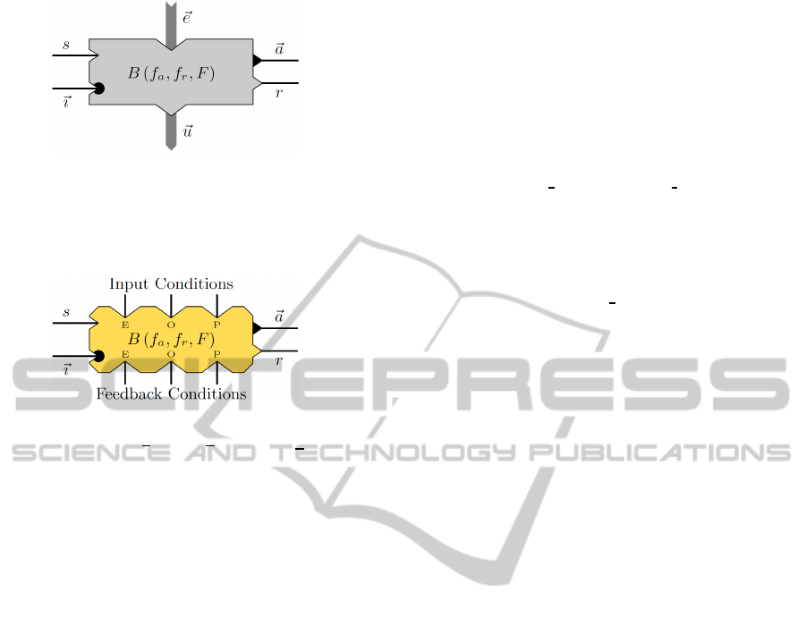
Figure 1: The general symbol of a behaviour showing stim-
ulation s, inhibition vector~ı, activity vector ~a, and target
rating r. ~e and~u denote the input and output vectors, respec-
tively. The transfer function F calculates u with respect to e
and the internal activation ι.
Figure 2: The symbol of a CBS module depicting the three
different types of ports (enabling, ordering, and permanent)
for input conditions (top) and feedback conditions (below).
As a CBS is a behaviour, it also features the standard be-
haviour ports.
put behaviours are connected. Hence the input condi-
tions are fulfilled depending on the activities or target
ratings of other behaviours. With the CBS’ activity,
another behaviour of the network, the stimulated be-
haviour, can then be stimulated.
Once active, a CBS monitors the values at a second
set of its input ports. If certain conditions concerning
these values are fulfilled, the CBS’ activity goes down
to zero again. As this can be used to send a feedback
from a stimulated behaviour to the CBS, these con-
ditions are called feedback conditions. By cascading
such constructs, arbitrarily complex behaviour activ-
ity sequences can be created.
A CBS acts as a coordinating element in a
behaviour-based network. (Saffiotti, 1997) identified
two aspects of the behaviour coordination problem,
namely how to decide which behaviour(s) to acti-
vate and how to combine the outputs of different be-
haviours into one command sent to a robot’s actua-
tors. In (Pirjanian, 1999), these two aspects are fur-
ther distinguished, resulting in a taxonomy with seven
different types of action selection mechanisms. The
behaviour coordination described in the paper at hand
falls into the category of state-based arbitration. The
state is determined by the input behaviours connected
to a CBS. By processing the input values as described
below, the CBS evaluates the state, and this evaluation
can constitute the basis for a behaviour arbitration.
3.2 Condition Evaluation
The conditions belonging to a CBS are evaluated as
described in the following. A relation ir
j
comparing
an input value with a threshold is attributed to each
input condition ic
j
. Such a relation is defined as fol-
lows:
ir
j
(t) =
1 input value
j
REL
j
input threshold
j
0 else
, (1)
where j = {1,.. . ,m}, m is the number of conditions,
t is the time, and REL
j
∈ {<,≤,=,≥, >}. Feedback re-
lations fr
j
are attributed to the feedback conditions fc
j
accordingly. Note that input value
j
(t) ∈ [0,1], i.e. there
is no limitation to {0,1}.
As in (Nicolescu and Matari´c, 2002), three differ-
ent types of conditions are distinguished here. They
can be used for the connection of input behaviours as
well as feedback behaviours to the CBS. In favor of a
better understanding, the focus shall be on input con-
ditions in the following and feedback conditions shall
be neglected. The three different types of conditions
are:
1. Permanent: The corresponding relation has to
be fulfilled during the whole time when the be-
haviour shall be active, i.e. the condition is ful-
filled if and only if the relation is fulfilled (cp.
Equation 2).
2. Ordering: The corresponding relation has to be
fulfilled at some point in time before the be-
haviour shall get active. The condition will stay
fulfilled independent of whether the relation stays
fulfilled or not (cp. Equation 3).
3. Enabling: The corresponding relation has to be
fulfilled at the exact point in time when the be-
haviour shall get active. After that, the condition
stays fulfilled independent of the fulfillment of the
relation (cp. Equation 4).
The following equations express this in a more
formal way.
Permanent:
ic
CBS
j
(t) =
1 if ir
j
(t) = 1
0 else
(2)
The fulfillment of a permanent condition at time t is
equal to the fulfillment of the corresponding relation
at time t.
Ordering:
ic
CBS
j
(t) =
1 if ∃t
0
≤ t : ir
j
(t
0
) = 1
0 else
(3)
ICINCO 2011 - 8th International Conference on Informatics in Control, Automation and Robotics
122
An ordering condition is fulfilled at time t if there
is a point in time t
0
≤ t at which the corresponding re-
lation was fulfilled. Note that no assumption is made
about the fulfillment of the relation after this moment
t
0
.
Enabling:
ic
CBS
j
(t) =
1 if ∃t
0
≤ t :
m
V
k=1
ic
k
enabling
ir
k
(t
0
) = 1
∧
m
V
k=1
ic
k
ordering
ic
k
(t
0
) = 1
∧
m
V
k=1
ic
k
perm.
ic
k
(t
1
) = 1 ∀t
1
: t
0
≤ t
1
≤ t
0 else
(4)
Enabling conditions are the most complex ones.
In order to determine whether an enabling condition
is fulfilled at time t, it has to be checked whether there
is a point in time t
0
≤ t at which all other conditions
were fulfilled. Furthermore, all conditions have to be
fulfilled from t
0
on. The fulfillment at t
0
is easy to
check for all types of conditions. To avoid cyclic de-
pendencies between different enabling conditions, the
relations ir instead of the conditions are checked for
them. The fulfillment for all t
1
with t
0
≤ t
1
≤ t follows
directly for enabling and ordering conditions. For per-
manent conditions, by contrast, it has to be checked
separately.
The behaviour signals of a CBS are calculated as
follows:
a
CBS
(t) = s
CBS
(t) ·
1− i
CBS
(t)
·
m
∏
j=1
ic
CBS
j
(t)
= ι
CBS
·
m
∏
j=1
ic
CBS
j
(t) (5)
r
CBS
(t) =
m
∏
j=1
ic
CBS
j
(t) (6)
3.3 Example Network
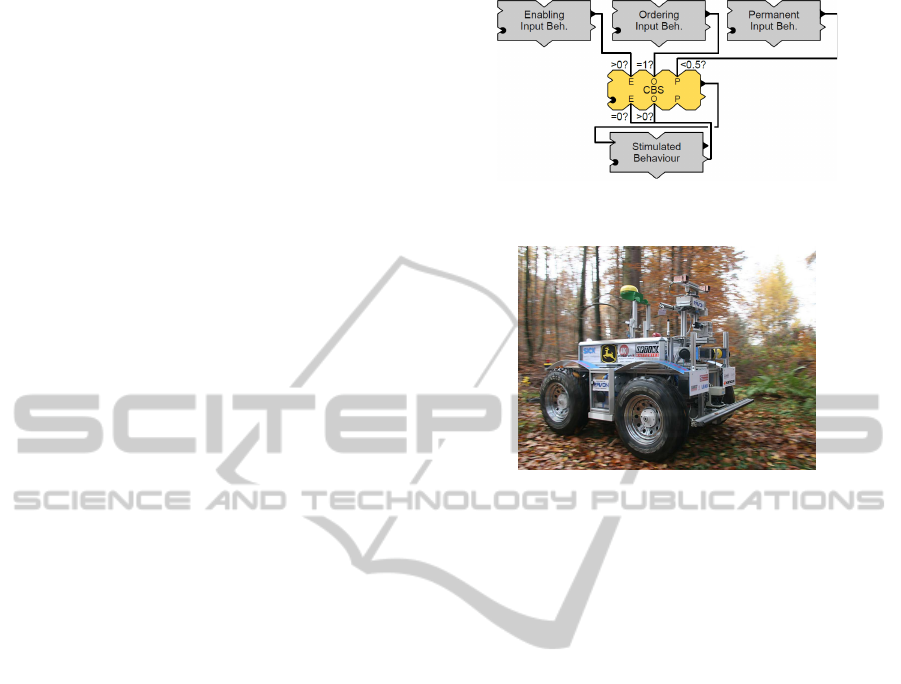
Figure 3 shows a simple behaviour network in which
a CBS connects three input behaviours and one stim-
ulated behaviour. The input conditions are fulfilled
from the point in time at which the enabling input
behaviour has an activity > 0 and the ordering input
behaviour had (or still has) an activity of 1. Further-
more, the activity of the permanent input behaviour
has to be < 0.5 as long as the input conditions shall be
fulfilled.
Figure 3: A simple exemplary network.
Figure 4: The autonomous off-road robot RAVON.
There are three connections between the CBS and
the stimulated behaviour: The activity output of the
CBS is connected to the stimulating input of the stim-
ulated behaviour, resulting in a stimulation as soon
as the activity of the CBS rises. Two further connec-
tions have been drawn from the target rating output
of the stimulated behaviour to two inputs of the CBS
associated with two feedback conditions. If the stimu-
lated behaviour is not fully satisfied with the situation
(r > 0), it will start executing its task as soon as it gets
stimulated by the CBS. The execution of the task can
take an arbitrary amount of time. During this time,
the stimulated behaviour will alter the situation in a
way that increases its satisfaction. Full satisfaction
is expressed by its target rating going back down to 0.
This signals the CBS that the stimulated behaviour has
completed its job and needs no further stimulation. It
shall be mentioned here that, of course, the stimulated
behaviour can fail in achieving its goal, resulting in its
target rating stay above 0. This kind of situation is not
unusual in complex system and can be dealt with, for
example, by a behaviour that monitors the situation
and takes action if no progress is made.
4 APPLICATIONS
Two examples shall illustrate the use of networks with
behaviour sequences. The first one shows how a turn-
ing manoeuvre can be realised, while the second one
describes how dead ends can be recognised using be-
USING BEHAVIOUR ACTIVITY SEQUENCES FOR MOTION GENERATION AND SITUATION RECOGNITION
123
haviour sequences. Both networks have been inte-
grated into the control system of the off-road vehicle
RAVON
2
(see Figure 4 and (Armbrust et al., 2010)).
The control system has been implemented using the
software framework MCA2-KL
3
. In order to limit
the influence of other subsystems that might react on
external influences and thereby complicate the inter-
pretation of the robot’s overall behaviour, the exper-
iments shown here have been conducted in simula-
tion. However, the behaviour-based network used is
the same as the one controlling the real robot and con-
sists of over 500 single behaviours.
4.1 Turning Manoeuvre
If a vehicle with a kinematics that does not allow for
turning on the spot shall be turned around in a nar-
row place between obstacles, several back and forth
manoeuvres are necessary. A component of a robot
control system realising this task has to determine
whether the robot is in a situation where conducting
such manoeuvres is desired and then decide in which
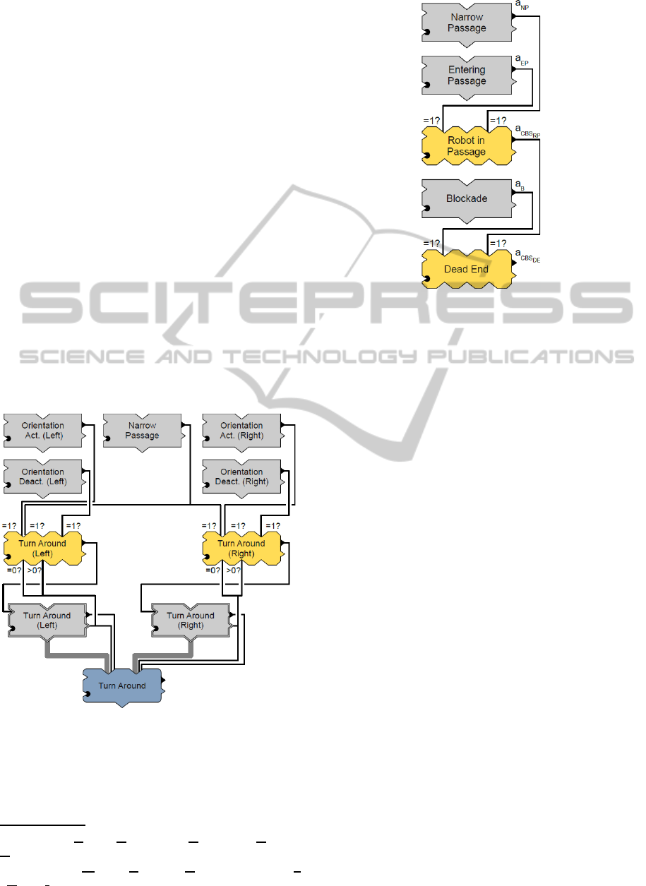
direction to turn around. Figure 5 shows a behaviour-
based network realising this task.
Figure 5: The behaviour-based network for turning around.
The network consists of two strings, one for turn-
ing back and forth to the left and one for turning to the
right. For each side, two behaviours (Orientation Ac-
tivation and Orientation Deactivation) check whether
2
RAVON: Robust Autonomous Vehicle for Off-road
Navigation.
3
MCA2-KL: Modular Controller Architecture Version 2
- Kaiserslautern Branch.
Figure 6: The behaviour-based network that recognises
dead ends.
the robot’s angle to the target is within certain lim-
its. Their activities are determined by the following
equations:
a
Orient. Act.
(t) =
ι
Orient. Act.
(t) if α
Target
(t) ≥ α
Act.
0 else
(7)
a
Orient. Deact.
(t) =
ι
Orient. Deact.
(t) if α
Target
(t) ≥ α
Deact.
0 else
(8)
α
Target
denotes the robot’s angle to the target. α
Act.
and α
Deact.
are two thresholds used to determine when
turning manoeuvres shall be executed. They have
been set to 90
◦
and 45
◦
, respectively. Together with
the use of the behaviours’ activities as enabling and
permanent input conditions, respectively, for a CBS,
this results in turning manoeuvres being initiated if
the robot’s angle to the target is above 90
◦
and being
continued until the angle falls below 45
◦
, realising a
hysteresis function. The activity of an additional be-
haviour (Narrow Passage) is used as enabling input
condition: It checks whether the robot is situated in a
narrow place. If this is not the case, no back and forth
manoeuvres are initiated. The reason for this is that
RAVON’s main sensor systems (like the ones of many
robots) are mounted at the front. Therefore, it shall
only drive backwards if absolutely necessary.
Depending on the fulfillment of the input condi-
tions, motion commands turning the robot to the left
or the right will be initiated by the behavioural groups
at the bottom (Turn Around (Left) and Turn Around
(Right)). Each of them is connected to the feedback
condition ports of the corresponding CBS in the way
ICINCO 2011 - 8th International Conference on Informatics in Control, Automation and Robotics
124

the stimulated behaviour in Figure 3 is. Hence, a CBS
will stay active and thus continue to stimulate a group
until the group’s target rating has risen and then gone
back down to zero. The group’s outputs are combined
by a behaviour fusion, which yields the network’s out-
put. Note that the change from forward to backward
motion and vice versa is also realised with the help of
CBSes in Turn Around (Left) and Turn Around (Right),
but is beyond the scope of the work at hand.
The advantage of realising such a functionality us-
ing behavioural networks is that the activity of the be-
haviours directly provides information about the state
of the system. For example, if the robot unexpect-
edly does not execute back and forth movements, then
by looking at the behaviour network with a special
analysis tool (see Figures 7c and 7d as well as (Proet-
zsch, 2010)) one can directly evaluate which of the
conditions is not fulfilled. This is a benefit especially
for more complex tasks and hence more complex net-
works than the one given here as example.
4.2 Dead End Recognition
Properly dealing with dead ends is an important abil-
ity for robots operating in complex environments.
Approaches using classic path planning algorithms
can deal with them as long as the whole dead end
is represented in their world model. RAVON, for
example, features path planning on a robot-centred
grid map with an extent of 50 m along each axis.
That means dead ends cannot be detected as complete
structure directly if they do not fit into this area. As
a result, a classic path planning algorithm will proba-
bly lead the robot into a dead end as soon as the cor-
responding blockade is not within the map anymore.
The approach presented here uses a behaviour net-
work to recognise dead ends that are larger than the
available world model.
In the context of this work, a dead end is defined
as a structure consisting of three elements:
1. Passage Entry: an opening between two obstacles
that leads into the dead end.
2. Narrow Passage: a corridor between obstacles in
which the robot cannot drive left or right but has
to move on (or back off, of course).
3. Blockade: the end of the passage, which keeps the
robot from moving on.
The idea here is to detect these three elements in
a certain sequence. A behaviour of the network shall
get active if the network has found out that the robot
is within a dead end. Of course, it must have driven
into it sometime. So driving through a passage entry
is the first condition, while the second is that the robot
is within a narrow corridor all the time after entering
the (probable) dead end. If at some point the robot
could also drive on to the left or the right, the structure
would not be regarded as dead end. Finally, the robot
must be faced with a blockade of its path, which is the
third condition.
Figure 6 depicts a behaviour network that realises
this functionality. Three rather simple behaviours are
used for the detection of the different aspects: En-
tering Passage, Narrow Passage, and Blockade. The
CBS Robot in Passage indicates that the robot has
driven through a passage entry and is now within
a narrow corridor, while the CBS Dead End shows
whether the robot is in a dead end or not.
The activity of Entering Passage (a
EP
) is defined
as follows:
a
EP
(t) = ι
EP
(t) ·passage entered(t)
= ι
EP
(t) ·
1 if the robot has driven
through a passage’s entry
before time t
0 else
(9)
Assuming that Entering Passage, Narrow Pas-
sage, and Blockade as well as the two CBSes Robot
in Passage and Dead End are always fully stimulated
and not inhibited, Equation 9 becomes:
a
EP
(t) =
1 if the robot has driven
through a passage’s entry
before time t
0 else
(10)
Accordingly, the following equations hold:
a
NP
(t) =
1 if the robot is within a narrow
passage at time t
0 else
(11)
a
B
(t) =
1 if a blockade is detected in front
of the robot at time t
0 else
(12)
As the detection of a dead end shall be indi-
cated by a
CBS
DE
= 1, the question is when this is the
case. Intuitively, this will be the case when the robot
faces a blockade after it has entered a narrow passage
which it has not left before encountering the block-
ade. Hence, the behavioural network fulfills the task
of recognising dead ends. A formal analysis of the
activity of Robot in Passage with Equations 2 and 4
USING BEHAVIOUR ACTIVITY SEQUENCES FOR MOTION GENERATION AND SITUATION RECOGNITION
125
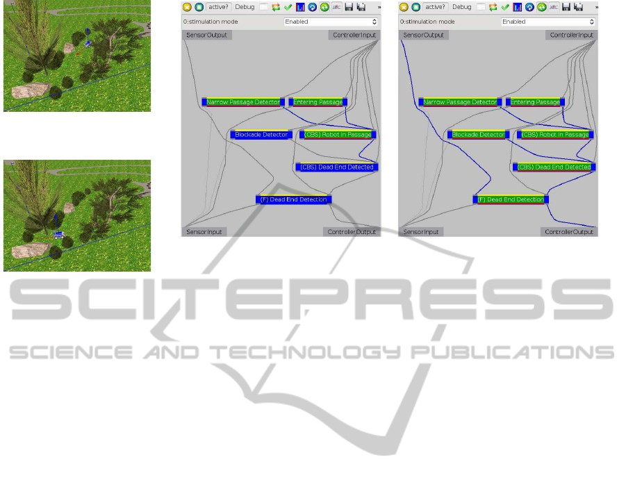
(a) RAVON is within the narrow pas-
sage.
(b) RAVON has reached the blockade
at the end of the passage.
(c) The behaviours Entering Passage and Narrow
Passage are fully active. Hence, the CBS Robot in
Passage also is. The fusion behaviour (marked with
“(F)”) determines this networks activity and target
rating.
(d) The behaviour Blockade Detector is now also
active, resulting in a high activity of the CBS Dead
End Detected. The group’s fusion behaviour is also
active, signalling external components that the robot
has driven into a dead end.
Figure 7: The behaviour-based network Dead End Detection recognises that RAVON has driven into a dead end. Figures (a)
and (b) depict two situations that occurred when the robot drove into the dead end, while Figures (c) and (d) illustrate the state
of the network in these two situations. The names of the behaviours differ slightly from the ones used in the work at hand.
in mind yields:
a
CBS
RP
(t) = 1 ⇔
ic
EP
(t) = 1
∧
ic
NP
(t) = 1
⇔
∃t
0
≤ t : a
EP
(t
0
) = 1
∧
∀t
1
: t
0
≤ t
1
≤ t : a
NP
(t
1
) = 1
(13)
A similar equation can be set up for Dead End:
a
CBS
DE
(t) = 1 ⇔
ic
B
(t) = 1
∧
ic
RP
(t) = 1
⇔
∃t
0
≤ t : a
B
(t
0
) = 1
∧
∀t
1
: t
0
≤ t
1
≤ t : a
CBS
RP
(t
1
) = 1
(14)
Using Equation 13 to replace a
CBS
RP
in Equa-
tion 14 yields:
a
CBS
DE
(t) = 1 ⇔
∃t
0
≤ t : a
B
(t
0
) = 1
∧
∀t
1
: t
0
≤ t
1
≤ t :
∃t
2
≤ t
1
: a
EP
(t
2
) = 1
∧∀t
3
: t
2
≤ t
3
≤ t
1
: a
NP
(t
3
) = 1
(15)
These considerations show that even rather sim-
ple behaviour-based networks containing CBSes can
realise functionalities that would require long, hard
to read terms if expressed in a mathematical way.
By contrast, diagrams depicting iB2C networks can
be understood fast by anyone who knows some ba-
sic symbols for the behaviour components and their
interaction methods. Additionally, special tools for
analysing behaviour networks can provide significant
support during the implementation and testing phases
of a new component. Several such tools exist for the
iB2C. One of them, the MCABrowser, is introduced
below.
Figure 7a shows RAVON in a simulated off-road
environment. It stands at the entry of a narrow pas-
sage that is blocked at its end by a large rock, making
it a dead end. The robot is commanded to drive to-
wards a target that is situated ahead of it, but outside
of the passage. Hence, it drives deeper into the pas-
sage until it detects the blockade (see Figure 7b).
Figures 7c and 7d are screenshots of the MCA-
Browser in iB2C mode, a tool used to analyse and
configure MCA2 programs. The iB2C mode features
special support for behavioural networks. Every blue
rectangle depicts a behaviour. The yellow, green, and
red bars visualise a behaviour’s activation, activity,
and target rating, respectively. With this visualisation,
a user can very fast get an insight into the state of a
behaviour-based system. Figure 7c shows that when
the robot has just entered the passage, the behaviours
Entering Passage and Narrow Passage are fully ac-
tive. In compliance with Equation 13, the CBS Robot
in Passage is also active and thus indicates that the
robot is situated in a passage belonging to the passage
entry through which it has just driven. When RAVON
has drivendeep enough into the passage, the blockade
gets into its sensor range (see Figure 7b). The Block-
ade Detector’s activity rises to 1 and so does the one
of Dead End Detected (see Figure 7d), which con-
forms to Equation 14.
ICINCO 2011 - 8th International Conference on Informatics in Control, Automation and Robotics
126

5 CONCLUSIONS AND
OUTLOOK
The paper at hand presented a concept for using
behaviour-based approaches to realise complex tasks.
This allows for benefiting from the advantages of
such approaches on high navigation layers. The au-
thors proposed the creation of behaviour activity se-
quences, which was illustrated using the example of
the behaviour-based architecture iB2C. It was ex-
plained how such sequences can be built up using
a generic coordination behaviour. The proposed ap-
proach allows for using analysis tools for behaviour-
based systems to examine networks consisting of ac-
tivity sequences and supports the reuse of single ele-
ments. Two examples were given to show how be-
haviour activity sequences can be used to generate
robot motions or recognise complex situations in off-
road environments.
In the future, the authors plan to use the coordinat-
ing behaviour for generating more complex manoeu-
vres and assessing other types of situations which a
robot can encounter in typical off-road environments.
Experiments with the real robot shall confirm the re-
sults obtained in simulation. Furthermore, an interac-
tion between this layer of the robot’s navigation and
the high-level navigation shall be established so that
the lower of the two layers can give feedback to the
higher one if the robot finds itself within a complex
situation. Thereupon the high-level navigation can al-
ter its strategy and trigger the execution of complex
manoeuvres in the layer below. For example, the in-
formation about the presence of a dead end could be
sent to the higher layer, where it would be stored in a
map and where an alternative route to the target would
be calculated.
REFERENCES
Arkin, R. (1998). Behaviour-Based Robotics. MIT Press.
Armbrust, C., Braun, T., F¨ohst, T., Proetzsch, M., Renner,
A., Sch¨afer, B.-H., and Berns, K. (2010). RAVON –
the robust autonomous vehicle for off-road navigation.
In Baudoin, Y. and Habib, M. K., editors, Using robots
in hazardous environments: Landmine detection, de-
mining and other applications, chapter RAVON – The
Robust Autonomous Vehicle for Off-road Navigation.
Woodhead Publishing Limited.
Brooks, R. (1986). A robust layered control system for a
mobile robot. IEEE J. Robotics and Automation, RA-
2(1):14–23.
Gat, E. (1998). Three-layer architectures. In Kortenkamp,
D., Bonasso, R., and Murphy, R., editors, Artificial In-
telligence and Mobile Robots, pages 195–210. AAAI
Press / The MIT Press.
Giesbrecht, J. (2004). Global path planning for unmanned
ground vehicles. Technical report, Defence Research
and Development Canada, Suffield, Canada. Techni-
cal Memorandum DRDC Suffield TM 2004-272.
Habib, M. K. (1999). Can planning and reactive systems
realize an autonomous navigation? In Proc. 30th Int.
Symposium on Robotics (ISR), Tokyo, Japan.
Maes, P. (1990). Situated agents can have goals. Designing
autonomous agents: Theory and practice from biology
to engineering and back, pages 49–70.
Matari´c, M. J. (1997). Behavior-based control: Exam-
ples from navigation, learning, and group behavior. J.
Experimental and Theoretical Artificial Intelligence -
Special Issue on Software Architectures for Physical
Agents, 9(2–3):323–336.
Nicolescu, M. and Matari´c, M. (2002). A hierarchical archi-
tecture for behavior-based robots. In Proc. First Int.
Joint Conference on Autonomous Agents and Multi-
Agent Systems, pages 227–233, Bologna, Italy.
Pirjanian, P. (1999). Behaviour coordination mechanisms
— state-of-the-art. Technical Report IRIS-99-375, In-
stitute for Robotics and Intelligent Systems, School of
Engineering, University of Southern California.
Proetzsch, M. (2010). Development Process for Complex
Behavior-Based Robot Control Systems. RRLab Dis-
sertations. Verlag Dr. Hut.
Ranganathan, A. and Koenig, S. (2003). A reactive robot
architecture with planning on demand. In Proc.
IEEE/RSJ IROS 2003, pages 1462–1468, Las Vegas,
Nevada, USA.
Saffiotti, A. (1997). The uses of fuzzy logic in autonomous
robot navigation. J. Soft Computing, 1(4):180–197.
USING BEHAVIOUR ACTIVITY SEQUENCES FOR MOTION GENERATION AND SITUATION RECOGNITION
127
