
APPLICATION INTEGRATION OF SIMULATION TOOLS
CONSIDERING DOMAIN SPECIFIC KNOWLEDGE
Tobias Meisen
Institute of Information Management in Mechanical Engineering, RWTH Aachen University
Dennewartstraße 27, Aachen, Germany
Philipp Meisen
Inform GmbH, Pascalstr. 23, Aachen, Germany
Daniel Schilberg, Sabina Jeschke
Institute of Information Management in Mechanical Engineering, RWTH Aachen University
Dennewartstraße 27, Aachen, Germany
Keywords: Application Integration, Data Integration, Simulation Tools, Ontology, Framework.
Abstract: Because of the increasing complexity of modern production processes, it is necessary to plan these proc-
esses virtually before realizing them in a real environment. On the one hand there are specialized simulation
tools simulating a specific production technique with exactness close to the real object of the simulation. On
the other hand there are simulations which simulate whole production processes, but often do not achieve
prediction accuracy comparable to the specialized tools. The simulation of a production process as a whole
achieving the needed accuracy is hard to realize. Incompatible file formats, different semantics used to de-
scribe the simulated objects and missing data consistency are the main causes of this integration problem. In
this paper, a framework is presented that enables the interconnection of simulation tools of production engi-
neering considering the specific knowledge of a certain domain (e.g. material processing). Therefore, an on-
tology-based integration approach using domain specific knowledge to identify necessary semantic trans-
formations has been realized. The framework provides generic functionality which, if concretized for a do-
main, enables the system to integrate any domain specific simulation tool in the process.
1 INTRODUCTION
Within the enterprising environment, the necessity to
couple deviating applications being used in a com-
pany was recognized early. As a consequence, vari-
ous concepts were developed that were subsumed
under the collective term “Data Integration Tech-
niques” (White, 2005). One of those techniques,
“Enterprise Application Integration” (EAI), focuses
on integrating business processes based on IT along
the value chain of an enterprise without taking into
account the platform, the architecture as well as the
generation of the applications being used in these
processes (Conrad, 2006). Especially in the widely
spread field of enterprise resource planning (Gronau,
2010) EAI technologies are well established. These
technologies are the foundation for such systems
concerning data and application integration. In other
fields, e.g. Business Intelligence (BI) or Enterprise
Performance Management (EPM), other data inte-
gration techniques (i.e. ETL, EII) are mainly used to
gain information about cross-applicational business
processes (Panian, 2005).
The combination of those integration techniques
to analyse more complex business processes, like
simulation processes, is seldom taken into account
(Schmitz, 2009). Simulation itself is a well-estab-
lished field in research and development and differ-
ent simulations for specific tasks as e.g. casting,
welding or cooling and also for whole processes
(e.g. transformation or heat-treatment processes) are
available. Nevertheless, those simulations have to be
42
Meisen T., Meisen P., Schilberg D. and Jeschke S..
APPLICATION INTEGRATION OF SIMULATION TOOLS CONSIDERING DOMAIN SPECIFIC KNOWLEDGE.
DOI: 10.5220/0003429700420053
In Proceedings of the 13th International Conference on Enterprise Information Systems (ICEIS-2011), pages 42-53
ISBN: 978-989-8425-53-9
Copyright
c
2011 SCITEPRESS (Science and Technology Publications, Lda.)
seen as isolated applications. They are often special-
ized for a single purpose (e.g. a specific task) and do
neither have standardized interfaces nor standardized
data formats. Therefore, different results that were
received within a simulation can only be integrated
into a simulation process if they are checked manu-
ally and are adapted to the needs of the subsequent
simulations. Current data integration techniques
cannot easily be applied to the simulation context
because a combination of different solutions is re-
quired. Huge data volumes which are characteristic
for simulation processes tend to use ETL solutions,
but a message-oriented transaction is not supported.
This message-oriented approach is realized in the
field of EAI solutions (e.g. ESB), although within
this field, huge data volumes cannot be handled
satisfactory. Another problem is the adaption of the
data integration process concerning changes within
the simulation process (e.g. the integration of a new
application, the modification of a simulated object)
and the semantics of data that have to be considered
by the integration.
In this paper, a framework will be described
which provides the possibility of simulating a pro-
duction process by making use of existing isolated
applications. The integration method uses ontologies
to describe the domain specific knowledge (e.g.
material processing simulations) and planning algo-
rithms to identify how the data can be transferred
between different heterogeneous simulation tools.
Thereby, the paper focuses on the integration of data
that was generated during the applications’ usage,
whereas the applications’ linkup technique, which
can be handled with the help of modern middleware
(Myerson, 2002), will not be stressed.
The framework has been validated on the foun-
dation of three production process simulations. A
line-pipe, a gear wheel and a top-box production
process were simulated, whereby each process con-
sists of up to six different simulation tools. The
framework was developed within the project “Inte-
grated Platform for Distributed Numerical Simula-
tion”, which is a part of the Cluster of Excellence
“Integrative Production Technology for High-Wage
Countries”.
The paper is structured as follows: In section 2,
the current state of technology will be outlined in
order to provide a foundation for section 3, in which
one of the simulated production processes is pre-
sented. Section 4 consists of a description of the
architecture of the framework that is completed in
section 5 by a specification of the used data integra-
tion method. Section 6 points out how the frame-
work needs to be extended with regard to the pre-
sented use case. In section 7, a conclusion and out-
look will be drawn from the insights generated in
this paper.
2 STATE OF THE ART
Since the nineties, data integration belongs to the
most frequented topics with reference to finding
answers to questions which are raised across appli-
cation boundaries (Halevy, 2006). Today, a multi-
tude of data integration products can be found which
are used in different fields of application, whereby
each technology can be assigned to one of three
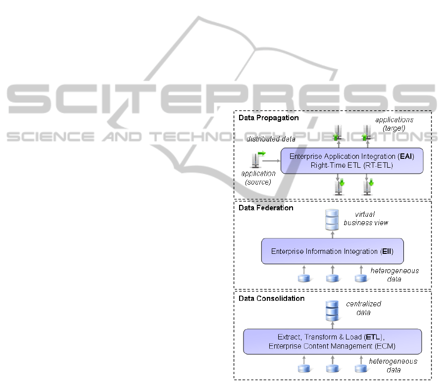
techniques (White, 2005) (cf. Figure 1):
• Data Propagation
• Data Federation
• Data Consolidation
Figure 1: Main areas of data integration (White, 2005).
With regard to the operational section, data
propagation is applied in order to make use of data
on a cross-application basis, which is often realized
via EAI. As already presented in (White, 2005), EAI
mainly focuses on small data volumes like messages
and business transactions that are exchanged be-
tween different applications. In order to realize EAI,
a contemporary architecture concept exists, which
APPLICATION INTEGRATION OF SIMULATION TOOLS CONSIDERING DOMAIN SPECIFIC KNOWLEDGE
43
was developed in connection with service-based
approaches (Chappell, 2004) and which will be
emphasized within this contribution – the so-called
Enterprise Service Bus (ESB). The basic idea of
ESB, which can be compared to the usage of inte-
gration brokers, comprises the provision of services
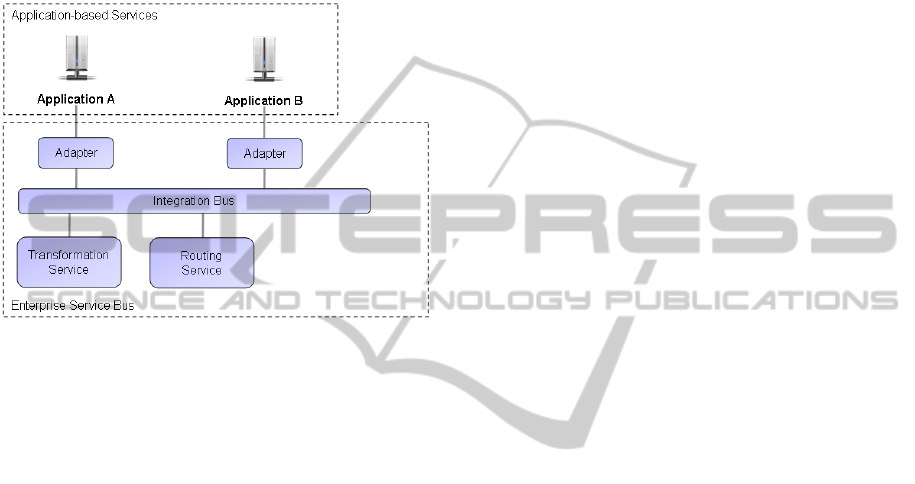
within a system (Schulte, 2002). Figure 2 illustrates
the schematic structure of an ESB.
Figure 2: Schematic structure of an Enterprise Service
Bus.
Within an ESB different services provide a tech-
nical or technological functionality with the help of
which business processes are supported. A service
can be a transformation or a routing service,
whereby all services are connected with each other
via the integration bus. Transformation services
provide general functions in order to transfer data
from one format and/or model into another. In con-
trast, routing services are used to submit data to
other services. Both transformation and routing
services are used by adaptors in order to transfer
data provided by the integration bus into the format
and the model of an application. Consequently,
transformation services support the reuse of imple-
mented data transformations. The advantage of a
solution based on ESB is to be seen in the loose
coupling of several services, whereas the missing
physical data coupling can be regarded as a disad-
vantage (Rademakers, 2008): If recorded data has to
be evaluated subsequently (e.g. with the help of data
exploration techniques like OLAP or Data Mining),
it has to be read out and to be transformed once
again. According to this fact, a historic or at least
long-term oriented evaluation of data is unconverti-
ble, even though such an evaluation is often re-
quired.
In order to realize such a unified examination on
a cross-data basis, other techniques belonging to the
field of data integration need to be taken into con-
sideration (cf. Figure 1). Data federation, which is
studied within the field of Enterprise Information
Integration (EII), might serve as one possible solu-
tion to enable a unified examination. With the help
of EII, data from different data sources can be uni-
fied in one single view (Bernstein, 2008). This sin-
gle view is used to query for data based on a virtual,
unified data schema. The query itself is processed by
the EII system and divided in several queries fired
against the underlying data sources. Because of the
fact that most EII do not support advanced data
consolidation techniques, the implementation will
only be successful if the data of the different data
sources can be unified, the data quality is sufficient
and if access to the data is granted (e.g. via standard
query interfaces).
If a virtual view is not applicable, techniques be-
longing to the field of data consolidation need to be
utilized. Data consolidation comprises the integra-
tion of differing data into a common, unified data
structure. Extract Transform Load (ETL) can be
seen as one example for data consolidation, which is
often used in the field of data warehousing (Vassi-
liadis, 2002). ETL starts with the extraction of data
from one or several – mostly operational – data
sources. The extracted data is than transformed (e.g.
joined, modified, aggregated) and the data model is
adapted to a final schema (often a so called star
schema). During the last phase the data is than
loaded into a target database (in general a data ware-
house).
The presented techniques of data integration
have in common that - independent of the technique
- the heterogeneity of data has to be overcome. In
literature, different kinds of heterogeneity are distin-
guished (Kim, 1991) (Goh, 1997) (Leser, 2007). In
this paper, the well-established kinds of heterogene-
ity listed in (Leser, 2007) are considered:
• Technical heterogeneity
• Syntactic heterogeneity
• Data model heterogeneity
• Structural or schema heterogeneity
• Semantic heterogeneity
The problems occurring with each type of het-
erogeneity concerning data integration are many-
sided. The problem of technical heterogeneity, ad-
dressing the issue of accessing the data, can be han-
dled for example with the help of modern message-
oriented middleware techniques (Myerson, 2002).
Syntactic heterogeneity, which arises as a result of
the representation of data (e.g. number formats,
character encoding), can be overcome using com-
ICEIS 2011 - 13th International Conference on Enterprise Information Systems
44
mon standards and conversion routines. The han-
dling of data model heterogeneity is more complex.
This kind of heterogeneity is given, if the data is
represented by different data models (e.g. relation
(RDBMS), hierarchical (XML) or structured
(CSV)). Modern data integration solutions provide
readers and writers to access data from popular data
models and besides that, other data models can be
implemented and supported through interfaces. The
most complex kinds of heterogeneity are the struc-
tural and the semantic heterogeneity. Structural
heterogeneity addresses the problem of representing
data in one data model in different ways. One exam-
ple is the usage of element attributes versus nested
elements in a XML document. Semantic heterogene-
ity comprises differences in meaning, interpretation
and type of usage of schema elements or data.
Schema and ontology matching as well as mapping
methods can be used to find alignments between
data schemas and to process these alignments in a
further step. Thereby, an alignment is a set of corre-
spondences between entities of the schemas that
have to be matched. In the past years, several match-
ing and mapping algorithms have been published
(Euzenat, 2007). However, the focus of these meth-
ods is often a database schema, a XML schema or an
ontology. Besides, the published methods do not
regard the domain specific knowledge to determine
the alignments (Giunchiglia, 2006).
3 USE CASE
Within this paper, the manufacture of a line-pipe
will be stressed as example use case. During the
manufacture several simulations via tools that are
specialized for these techniques are used. The goal is
the simulation of the whole production process,
whereby the results of each specialized tool will be
considered across the whole simulated production
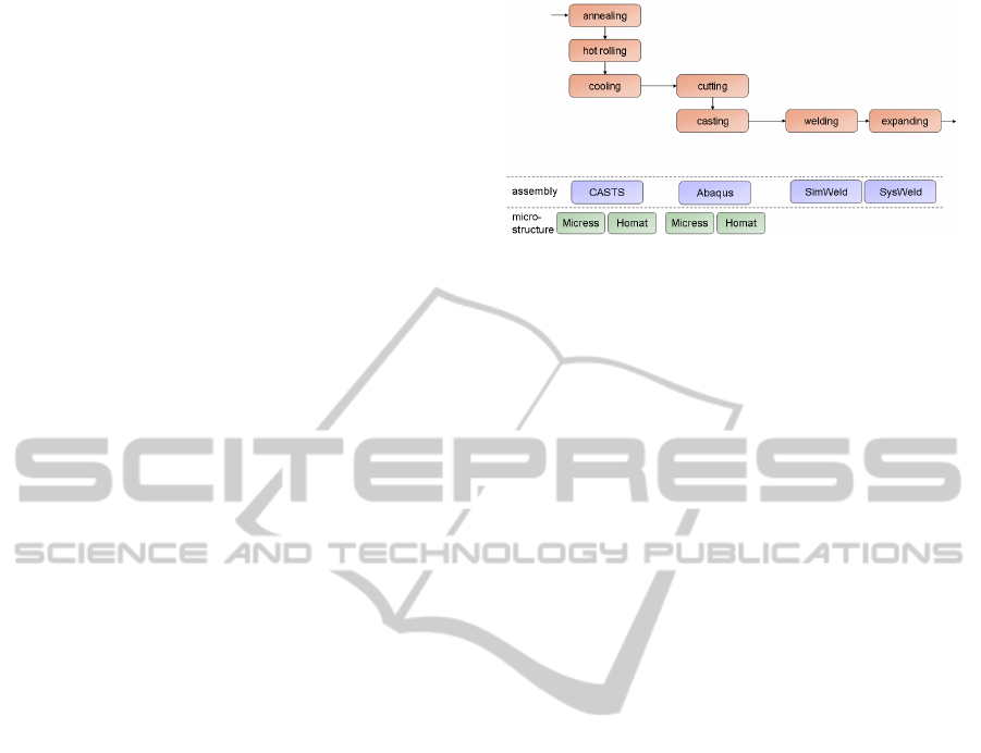
process. The production process which will be used
to exemplify the example use case is illustrated in
Figure 3.
The use case starts with a simulation of the an-
nealing, the hot rolling as well as the controlled
cooling of the components via CASTS, an applica-
tion developed by Access.
The next step consists in representing the cutting
and the casting with the help of Abaqus (Dassault
Systems), whereas the welding and the expanding of
the line-pipe will be simulated via SimWeld, a tool
which was developed by the ISF (RWTH Aachen
University), and via SysWeld, a software product
contrived by the ESI-Group (Rossiter, 2007).
Figure 3: Production process of a line-pipe.
Furthermore, the simulation of modifications in
the microstructure of the assembly will be realized
by making use of Micress (Laschet, 1998) and
Homat (Laschet, 2002) which were both developed
by Access. All in all, the use case contains six dif-
ferent kinds of simulations, each based on different
formats and models. Thereby, the required integra-
tion solution has to take different requirements into
account (Schilberg, 2010). Two requirements, which
turned out to be central with reference to the frame-
work presented in this paper, are on the one side, the
possibility of data propagation, focussing the seman-
tic data exchange between the applications, and, on
the other side, the necessity of a process-oriented
data consolidation (cf. Figure 1). Both of them are
used to facilitate a subsequent visualization and
analysis of data collected within the process. An-
other important requirement which has to be fulfilled
is the easy adaption of the whole simulation (i.e. the
simulation of the production process) concerning
changes of the process (e.g. adding or replacing
simulation tools, optimizing the process itself).
4 ARCHITECTURE
OF THE FRAMEWORK
4.1 System Architecture
The framework’s architecture is based on the re-
quirements described in section 3. The architecture
is depicted in Figure 4. As illustrated, the framework
follows the architecture concept of ESB, whereby
the possibility of data consolidation was realized by
implementing a central data store (Schilberg, 2008),
the database server.
APPLICATION INTEGRATION OF SIMULATION TOOLS CONSIDERING DOMAIN SPECIFIC KNOWLEDGE
45
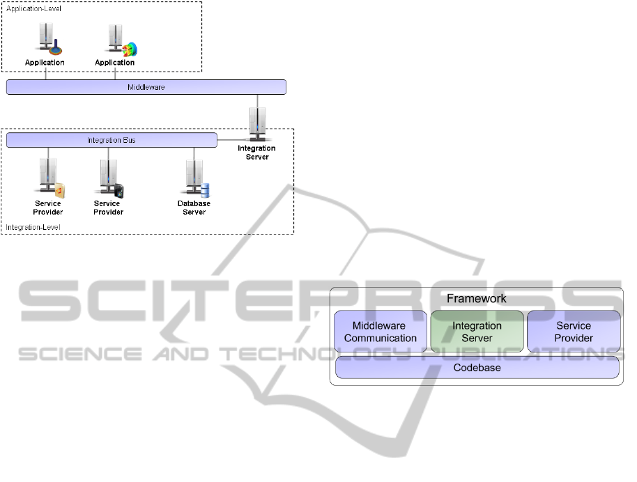
Figure 4: System-architecture of the framework.
In order to realize a communication (e.g. con-
cerning the exchange of files and overcome the
technical heterogeneity) between the integration
server and the different simulation tools (i.e. applica-
tions) a middleware is used that encapsulates the
functionality of routing services which are typical of
those used in ESB concepts
1
. Hence, routing ser-
vices are not considered in this framework, as the
integration of a standard middleware is straight for-
ward. The framework is employed with the intention
of realizing an integration level, at which service
providers, which are directly linked to the integra-
tion bus, offer different services. With the help of
these services, data can be integrated, extracted and
transformed. As the connection is realized via the
Java RMI Technology, it is not bound to the operat-
ing system in use. The employment of an integration
server as well as of a database server marks an im-
portant difference between the architecture described
in this section and the ESB architecture concept. The
integration server receives all data transferred by the
middleware, analyses it and, subsequently, makes it
available for each of the service providers via the
integration bus. In turn, the service providers tap the
required data in order to process it. After a step of
processing is finished, the integration server checks
the consistency of the data with the aim of determin-
ing the next step.
Consequently, with regards to the processes of
data integration and data extraction, the integration
server undertakes the task of a central supervisory
authority. A database server is used additionally as a
central data store, which is also linked to the integra-
_________________________
1
Within the use case mentioned in section 3 the application-
oriented middleware Condor (Cerfontaine, 2008) is used.
tion bus. The service provider and also the integra-
tion server have access to the database server,
whereby data consolidation and, as a result, analyses
of data collected during the process are possible.
4.2 Software Architecture
The framework comprises three main components:
• Middleware Communication
• Integration Server
• Service Provider
In order to guarantee a connection between those
components, a codebase component is needed, in
which a cross-component functionality is encapsu-
lated. The main components are illustrated in Figure
5. In the following, they will be described in detail.
Figure 5: Main components of the framework.
Middleware Communication: The Middleware
Communication component supports the realisation
of communication processes between the middle-
ware and the integration server. It contains adaptors,
which facilitate the transmission of demands to the
integration server by making use of different com-
munication protocols, such as TCP/IP, RMI or
SOAP (Kashyap, 2008). As far as a concrete use
case is concerned, which is not covered by technolo-
gies that were already integrated, the component is
modular expandable, which enables the implementa-
tion of additional separate adaptors (cf. section 5).
Integration Server: The component called “Inte-
gration Server” comprises the implementation of a
management component, which functions as a ser-
vice provider and a central control unit for integra-
tion processes. The services provided by this com-
ponent involve the integration, the extraction and the
transformation of data. For each of these services, a
service process is stored within the integration
server, which is started and processed as soon as a
client directs a question to the integration server
concerning the corresponding service. A service
process describes which services need to be handled
with the purpose of providing the functionality re-
quested by the client. The service processes realized
within the framework are illustrated in Figure 6.
ICEIS 2011 - 13th International Conference on Enterprise Information Systems
46
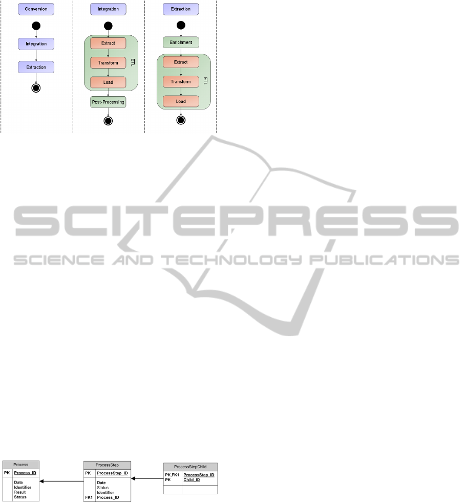
Figure 6: Service Processes of the framework.
The conversion process is defined by an integra-
tion process and an extraction process which are
both based upon extended ETL process. Within the
integration process, a post-processing of integrated
data is succeeded, whereas the extraction process
makes use of a data enrichment that is carried out
prior to the actual ETL process. Furthermore, the
steps which are marked green in Figure 6 are func-
tionalities that are made available by the service
provider within the integration level.
Thereby, the integration server is used as a me-
diator with the help of which data is exchanged to
those service providers that feature the postulated
functionality and capacity. As a consequence, the
algorithms, which are important for the process of
data integration and which are depending on the use
case in question, are encapsulated within the speci-
fied service providers. Additionally, the integration
server realizes a process-related integration of data.
Thereby, the integration server controls the assign-
ment of data to the process step and transmits the
context of the process in question to the service
providers. The underlying entity-relationship model
is depicted in Figure 7.
Figure 7: ER-model for process dependent data integra-
tion.
Within this model, a process is marked by a
name (attribute identifier), whereas each process
step has an arbitrary name at its disposal (attribute
identifier).
The course of the process is indicated by storing
the successors of each process step, which are not
restricted to a fixed number. In this way, complex
processes - such as the provision of simulation data
at the micro level (microstructure) as well as at the
macro level (assembly) - can be taken into account.
Service Provider: This component provides the
fundamental functionality for service providers
within the framework, whereby the implementation
of a concrete service provider depends on the par-
ticular use case. For instance, the integration of FE
data on the one hand and the integration of data of
molecular structures on the other hand are based
upon different data schemas, even though these
processes of integration consist in the same physical
object and deal with comparable physical entities.
The framework offers interfaces to common ETL
tools as, for example, the Pentaho Data Integrator
(PDI) (Lavigne, 2006). Thus, the integration and
extraction of data, and therefore the overcoming of
the syntactical and data model heterogeneity, can be
created on the basis of these tools, which are already
established in the domain of ETL. Furthermore,
additional tools or frameworks can also be used in
order to realize the processes of integration and
extraction in the case that this way of proceeding is
convenient and necessary within a concrete use case
(cf. section 5).
Apart from services which provide an ETL proc-
ess, the framework supports additional services in
order to post-process and enrich data. For instance,
the post-processing service allows the implementa-
tion of plausibility criteria, which need to be fulfilled
by the integrated data without reference to their
original source. During the process of enrichment,
data transformations are carried out with the purpose
of editing data stored within the central data store in
such a way that the data is able to meet the require-
ments demanded with regard to the extraction proc-
ess. Therefore an adaptive data integration process
(Meisen, 2009) is implemented in the framework. In
the following section, the idea and the implementa-
tion of the adaptive data integration are described.
5 ADAPTIVE DATA
INTEGRATION
5.1 Concept
The main goal of the adaptive data integration is to
overcome the problems of structural and semantic
heterogeneity considering domain specific know-
ledge. The adaptive data integration is part of the
enrichment process step in the extended ETL proc-
ess being used during the extraction of data. The
APPLICATION INTEGRATION OF SIMULATION TOOLS CONSIDERING DOMAIN SPECIFIC KNOWLEDGE
47
goal of the extraction process is to generate data in a
given data format, regarding the data model and
structure, as well as the semantics, of this format.
Therefore, the implemented enrichment enables the
discovery and exploitation of domain specific
knowledge. The concept is based upon ontologies
and planning algorithms from artificial intelligence.
According to (Gruber, 1993) an ontology is an ex-
plicit specification of a conceptualization. In this
paper, the stricter definition given in (Studer, 1998)
is used, in which an ontology is described as a for-
mal, explicit specification of a shared conceptualiza-
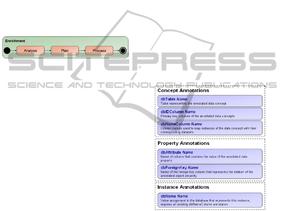
tion. The underlying enrichment process is depicted
in Figure 8.
Figure 8: Enrichment process.
First, the existing data is analysed. The goal of
the analysis is the determination of so called features
that are fulfilled by the data. A feature is domain
specific and expresses a structural or semantic prop-
erty that is satisfied by the data. Besides the analysis
step determines features that have to be fulfilled by
the data to satisfy the requirements of the specific
output format of the extraction process. Following
the analysis the planning algorithms are used to find
a data translation that transforms and enriches the
data, so that the enriched data fulfils the features
needed by the output format. After the planning is
finished, the found data translation is processed. The
data transformation algorithms used for the data
transformation are realized as a service. The infor-
mation about the existing transformations and fea-
tures is stored in an ontology. The basic structure of
this ontology is described in the following section.
5.2 Ontology
The information used by the enrichment process is
subdivided among a framework ontology and a do-
main ontology. The domain ontology holds informa-
tion about the concrete transformations, features and
applications used in the context of a specific domain.
Besides, information about the domain specific data
schema is stored. An extract of the domain ontology
used to implement the use case is described in sec-
tion 6. There are many languages for defining on-
tologies (Staab, 2009). The used ontologies are ex-
pressed in OWL, which is the ontology language
recommended by the W3C.
The domain ontology has to specialise the con-
cepts of the framework ontology in order to specify
the conceptualization of the domain. Hence, the
framework ontology is a specification of the con-
cepts used in the framework to enable the enrich-
ment process. These main concepts are data, feature,
application and transformation, which are intro-
duced shortly.
The concept data is the generalization of all data
concepts used in the domain. More precisely each
concept in the domain ontology used to describe the
data schema of the domain has to be a specialization
of the concept data. The mapping between data
concepts and the data schema of the domain is real-
ised by using a predefined set of annotations. Be-
cause of the single mapping between a well-known
ontology and a well-known database schema, auto-
matic schema matching algorithms are not used.
Instead this approach follows the concept of annota-
tion-based programming. Figure 9 gives an overview
of the main annotations.
Figure 9: Ontology annotations.
To define domain specific features, the concept
feature is used. A specialization of the concept fea-
ture is a listing of the requirements that have to be
satisfied by a set of data. If these requirements are
satisfied, the feature is fulfilled by the given data.
For each definition of applications and their re-
quirements, instances of the concept application
have to be expressed in the domain ontology. Be-
sides the requirements that are expressed using fea-
tures, an instance of the concept application can
have additional object properties to express domain
specific information of an application. Similar to an
ICEIS 2011 - 13th International Conference on Enterprise Information Systems
48
application, a transformation has requirements that
have to be satisfied. Otherwise, the transformation
cannot be used. Therefore, each instance of the con-
cept transformation has to outline the requirements
by defining instances of feature concepts. In addi-
tion, a transformation changes the features of the
data. This is realised by expressing the effects of the
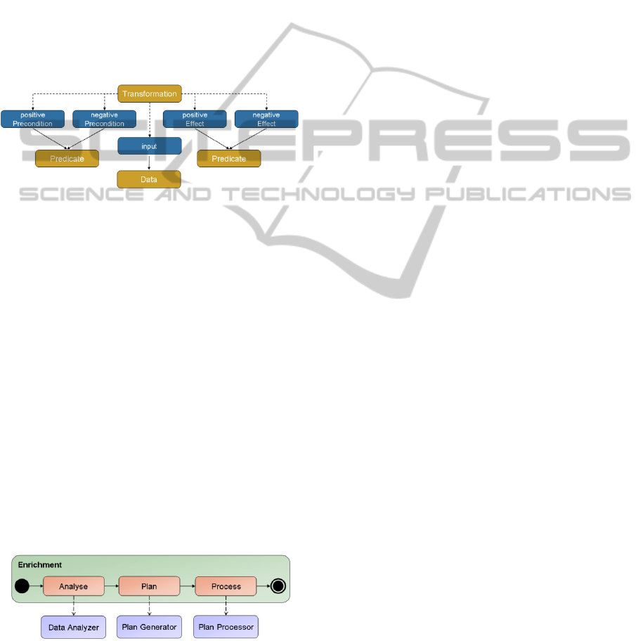
transformation in the ontology. The concept trans-
formation and its main relations are depicted in
Figure 10. The colour code of the figure is identical
to the colour code used in the ontology editor Pro-
tégé (Knublauch, 2004). The used graphical repre-
sentation of an ontology is taken from (Euzenat,
2007).
Figure 10: Fragment of framework ontology - transforma-
tion concept.
The input is set by an instance of the concept
data, whereby the requirements are expressed by
instances of either positivePrecondition or negative-
Precondition. These object properties realize rela-
tions between the concrete transformation and fea-
ture instances. The framework ontology provides a
set of logical connectives and quantifiers to express
complex requirements like feature1 or feature2.
Similarly, the effects of the transformation are ex-
pressed.
5.3 Components
The concept of the adaptive data integration is real-
ized by three subcomponents of the data manage-
ment component. Each component implements one
of the previously (cf. Figure 8) described steps of the
enrichment process (cf. Figure 11).
Figure 11: Implementation of the enrichment process.
The Data Analyser loads the ontology and es-
tablishes a connection to the data storage. By using
the domain ontology, the features of the domain are
determined. This is done by querying all defined
specializations of the concept feature. Therefore, the
OWL API (Horridge, 2009) and the reasoner Pellet
(Sirin, 2007) are used. The fulfilment of a feature is
checked by querying the data storage. The queries
are generated by using the annotation based map-
ping. At the moment, the Data Analyser only sup-
ports relational databases as central data storage and
SQL as a query language.
The result of the query is analysed according to
the feature definition. The use of database technol-
ogy instead of reasoning was necessary because of
the huge amount of data produced in the domain of
material processing. For example, the classification
of the geometry feature plain using reasoning with-
out database support takes 26 minutes analysing a
geometry with 2,000 nodes. On the contrary, the
reasoning using database queries takes less than one
second.
The fulfilled features define the initial state of
the data. In addition, the goal state is determined by
the Data Analyser using reasoning. This means that
the current context (required output format and do-
main specific parameters) is used to query the re-
quired features by using the information stored in
the domain ontology.
Hence, the result of the Data Analyser consists of
the initial and the goal state. This information is
passed to the Plan Generator to determine the
needed data translation. Therefore, the Plan Genera-
tor queries the existing data transformations from the
domain ontology and generates a problem descrip-
tion using the Planning Domain Definition Lan-
guage (PDDL) (Fox, 2003). By using a planner the
Plan Generator tries to solve the given planning
problem. The planner is used to determine a se-
quence of, so called actions that lead from the initial
state to a goal state. The framework supports differ-
ent planning algorithms like forward, backward and
heuristic search, STRIPS algorithm or Planning
Graphs (Ghallab, 2004) (Hoffmann, 2001). If the
planner succeeds a plan is generated that contains
the transformations and their ordering to transform
the data, so that the required features are fulfilled by
the data after having processed the plan. Finally, the
processing of the plan is realized by the Plan Proces-
sor. An example of the enrichment process will be
given in the following section.
APPLICATION INTEGRATION OF SIMULATION TOOLS CONSIDERING DOMAIN SPECIFIC KNOWLEDGE
49
6 APPLICATION
OF THE FRAMEWORK
Within the domain of the use case described in sec-
tion 3 and the requirements resulting from the ex-
amination of four additional use cases in the domain
of FE-simulations, an integration platform has been
implemented in parallel to the implementation of the
framework. The integrated applications are simula-
tions based upon the finite-element-method. In order
to implement the integration platform a domain
specific data schema, adaptors for integration and
extraction, the transformation library and the domain
ontology have been provided. In the following, some
selected examples will be presented.
Data schema: The domain specific data schema
has been determined by analysing the different input
and output formats of the simulations used in the use
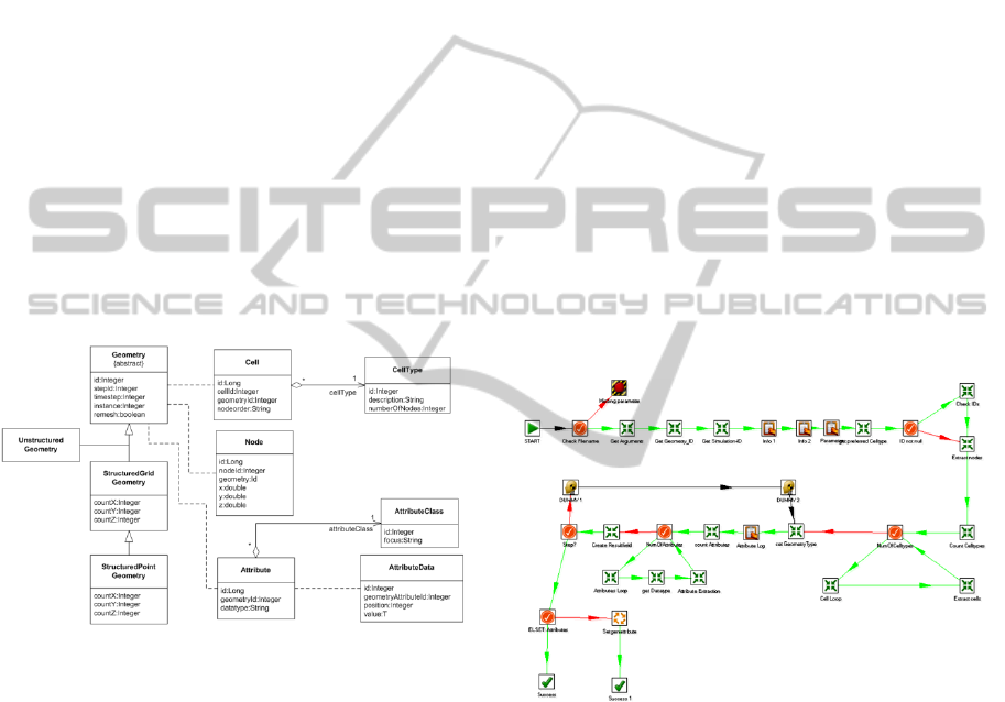
case. Figure 12 depicts an extract of the generated
data schema. The schema is drafted using the UML
notation.
Figure 12: Extract of the data schema used in the domain
of FE-simulations.
Within this data schema, the geometry of the as-
sembly is the central entity. It consists of nodes,
cells and attributes. The latter ones exhibit attribute
values, which are assigned to individual cells or
nodes depending on the class of attributes available
in the whole geometry. The integration services,
which were specified within the use case, read in the
geometrical data provided by the simulation, trans-
form it into the central data model and upload the
results into the database. In contrast, the extraction
services proceed as follows: The geometrical data is
read out from the central database and transformed
into the required format. Finally, the data is up-
loaded into the destination file or into the target
database. Because of the prior enrichment, all of the
structural and semantic data transformations have
been performed. Hence, most of the data transforma-
tions formerly performed by the adaptors are omit-
ted.
Adaptors: Most of the adaptors have been im-
plemented using the PDI. If more complex data have
been given, or binary formats that can only be read
by programming interfaces of the manufacturer,
either the PDI functionality have been extended
using the provided plug-in architecture or the needed
functionality has been implemented using Java or
C++. For example, the simulation results generated
within the simulation tool CASTS are stored in the
Visualization Toolkits (VTK) format (Schroeder,
2004).
Hence, an integration service was implemented,
which is based on the programming interface pro-
vided by the developers of VTK using the provided
functionality of the framework. Furthermore, an
extraction service was developed with regard to the
Abaqus input format, whereby, in this case, the
aforementioned ETL tool PDI was used. In Figure
13, an excerpt of the implemented PDI job is illus-
trated.
Figure 13: Abaqus extraction as PDI transformation.
Transformation Library: In order to realize the
data integration, different sorts of data transforma-
tions for FE data were implemented into the applica-
tion, for example the conversion of attribute units,
the deduction of attributes from those ones that are
already available, the relocating of the component’s
geometry within space, the modification of cell
types within a geometry (e.g. from a hexahedron to a
tetrahedron) or the re-enumeration of nodes and
cells.
Domain Ontology: In order to enable the adap-
tive data integration, the domain specific informa-
tion has been expressed in the domain ontology. As
ICEIS 2011 - 13th International Conference on Enterprise Information Systems
50
described above, the domain ontology uses the con-
cept of the framework ontology to express the data
schema, the transformations, the applications and the
features of the domain. Figure 14 sketches a frag-
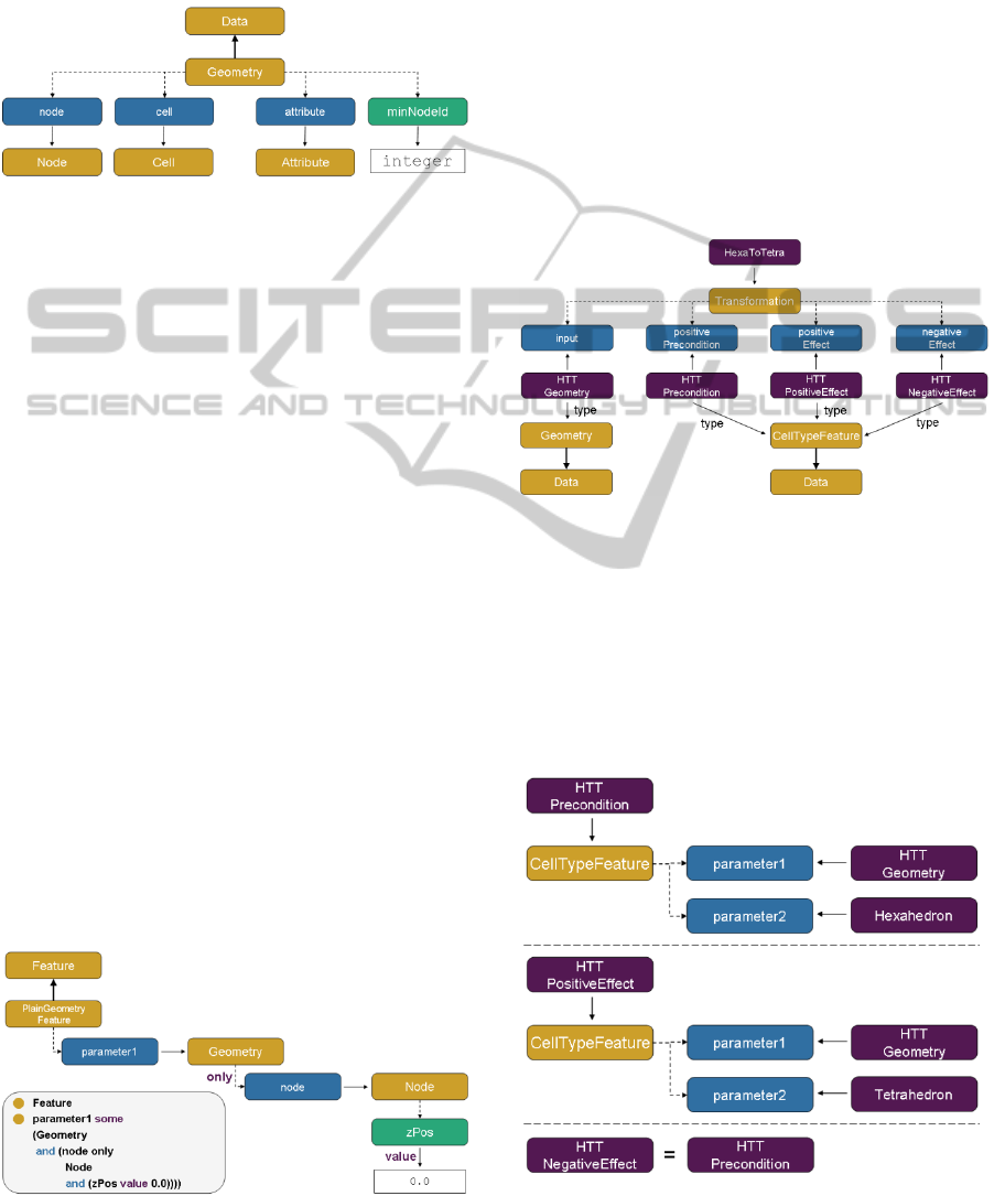
ment of the concept Geometry.
Figure 14: Fragment of the concept Geometry.
Because of the number of data and object proper-
ties, only a few are depicted. Most interesting is the
data property minNodeId, which is a sub-property of
minimumValueProperty. This kind of data property
can be used to prompt the Data Analyser to use the
SQL MIN function, whenever a classification re-
quires such information. Analogous data properties
for average and maximum exist within the frame-
work ontology. The depicted object properties node,
cell and attribute represent the relation between the
concept Geometry and the concept referred to by the
object property. Using the previously described
annotations the metadata of the relationship like
primary and foreign keys are expressed.
The defined data schema is used to point out dif-
ferent data features of the domain. As described
previously, a feature is a kind of classification of
existing data. More precisely, if all conditions of a
feature are fulfilled, the data belongs to the class
represented by the feature. A simple feature is the
already mentioned PlainGeometryFeature of the
concept Geometry. It expresses that a geometry
belongs to the class of plain geometries if all nodes
of the geometry have the z-coordinate zero. The
feature is expressed in the domain ontology as de-
picted in Figure 15. The statement used in Protégé to
express the feature is sketched as well.
Figure 15: Expression of the PlainGeometryFeature.
Besides the data schema and the features the on-
tology contains information about the available
transformations and the used applications. One ex-
ample of a transformation is HexaToTetra that trans-
forms a geometry based on hexahedrons into a ge-
ometry of tetrahedrons. The transformation searches
all occurrences of hexahedrons within the geometry
and splits them into tetrahedrons without creating
new nodes. Hence, the precondition of the transfor-
mation is that at least one hexahedron exists in the
geometry. The effect is that all hexahedrons are
replaced by tetrahedrons. Preconditions and effects
are expressed by using features. The expression of
the transformation HexaToTetra in the domain on-
tology is illustrated in Figure 16.
Figure 16: Expression of the transformation HexaToTetra.
As described previously a concrete transforma-
tion is expressed by an instance of the concept trans-
formation. According to Figure 10 object properties
have to be defined to express input, preconditions
and effects. The instance HTTGeometry expresses
that the transformation requires a geometry as an
input. The preconditions and effects are depicted
more detailed in Figure 17.
Figure 17: Expression of preconditions and effects in
HexaToTetra.
APPLICATION INTEGRATION OF SIMULATION TOOLS CONSIDERING DOMAIN SPECIFIC KNOWLEDGE
51
The precondition is a concrete CellTypeFeature
expressing that the geometry HTTGeometry consists
of cells of the cell type hexahedron. Also, the effects
are expressed using CellTypeFeature. The positive
effect is that the resulting geometry contains cells of
the type tetrahedron, whereas the negative effect is,
that the concrete CellTypeFeature representing the
hexahedron is forfeited.
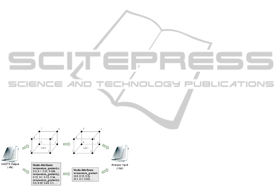
Example: Concluding this section, a small exam-
ple of the data provision of results generated by the
simulation CASTS to the simulation Abaqus is pre-
sented. The example focuses on the structural
changes of the data that are needed, in order to en-
able the usage of the data in Abaqus. Using the VTK
data format, the indexing of nodes and cells begins
with zero. Instead, Abaqus requires a sorted index-
ing starting with one. Additionally, in CASTS, vec-
tors are decomposed into single components and
stored as attribute values assigned to nodes, whereas
in Abaqus, vectors need to be quoted entirely.
Due to the data enrichment, the needed data
transformations have been determined autono-
mously. In Figure 18, a simplified illustration of the
result of data translation from CASTS to Abaqus,
which was specified for the use case described
above, is presented.
Figure 18: Simplified illustration of the data translation.
7 CONCLUSIONS
The development of the framework presented in this
paper can be regarded as an important step in the
establishment of integrated simulation processes
using heterogeneous simulations. Both, data losses
as well as manual, time-consuming data transmis-
sions from one tool to another are excluded from this
approach. The suggested framework facilitates the
linking of simulation tools, which were - until now -
developed independently and which are specialized
for certain production processes or methods, too.
Furthermore, the integration of data generated in the
course of the simulation is realized in a unified and
process-oriented way. Apart from the integration of
further simulation tools into an application, which
was already established, it is essential to extend the
domain of simulations reflected upon with additional
simulations covering the fields of machines and
production. In this way, a holistic simulation of
production processes is provided. Thereby, a major
challenge consists in generating a central data
model, which provides the possibility of illustrating
data uniformly and in consideration of its signifi-
cance in the overall context, which comprises the
levels of process, machines as well as materials. Due
to the methodology presented in this article, it is not
necessary to adapt applications to the data model
aforementioned. On the contrary, this step is realized
via the integration application, which is to be devel-
oped on the basis of the framework. Because of the
unified data view and the particular logging of data
at the process level, the framework facilitates a
comparison between the results of different simula-
tion processes and those of simulation tools. Fur-
thermore, conclusions can be drawn much easier
from potential sources of error - a procedure which
used to be characterized by an immense expenditure
of time and costs. The realization of this procedure
requires the identification of Performance Indicators,
which are provided subsequently within the applica-
tion. In this context, the development of essential
data exploration techniques on the one side and of
visualization techniques on the other side turns out
to be a further challenge.
ACKNOWLEDGEMENTS
The approaches presented in this paper are supported
by the German Research Association (DFG) within
the Cluster of Excellence “Integrative Production
Technology for High-Wage Countries”.
REFERENCES
Bernstein, P., A., Haas, L. M., 2008. Information
integration in the enterprise. In Communications of
the ACM - Enterprise information integration and
other tools for merging data, vol. 51, no. 9, pp. 72-79.
Cerfontaine, P., Beer, T., Kuhlen, T., Bischof, C., 2008.
Towards a exible and distributed simulation platform.
In ICCSA '08: Proceedings of the international confer-
ence on Computational Science and Its Applications,
Part I, pp. 867-882, Springer-Verlag, Heidelberg.
Chappell, D., 2004, Enterprise Service Bus: Theory in
Practice, O'Reilly Media, 1
st
edition.
ICEIS 2011 - 13th International Conference on Enterprise Information Systems
52

Conrad, S., et. Al., 2006. Enterprise Application
Integration: Grundlagen, Konzepte, Entwurfsmuster,
Praxisbeispiele, Spektrum, Heidelberg, 1
st
edition.
Euzenat, J., Shvaiko, P., 2007. Ontology matching.
Springer, Berlin, 1
st
edition.
Fox, M., Long, D., 2003. PDDL2.1: An extension to
PDDL for expressing temporal planning domains. In
Journal of Artificial Intelligence Research, vol. 20, p.
2003.
Ghallab, M., 2004. Automated planning: theory and prac-
tice. Elsevier/Morgan Kaufmann, Amsterdam.
Giunchiglia, F., Shvaiko, P., Yatskevich, M., 2006,
Discovering missing background knowledge in ontolo-
gy matching. In Proceeding of the 2006 conference on
ECAI 2006, pp. 382-386, IOS Press.
Goh, C., H., 1997. Representing and reasoning about
semantic conicts in heterogeneous information sys-
tems, PhD thesis, Massachusetts Institute of Tech-
nology.
Gronau, N., 2010. Enterprise Resource Planning:
Architektur, Funktionen und Management von ERP-
Systemen, Oldenbourg, 2
nd
edition.
Gruber, T., R., 1993. A translation approach to portable
ontology specifications. In Knowledge Acquisition,
vol. 5, pp. 199-220.
Halevy, A., Rajaraman, A., Ordille, J., 2006. Data
integration: the teenage years. In VLDB'2006:
Proceedings of the 32nd international conference on
Very large data bases, pp. 9-16, VLDB Endowment.
Hoffmann, J., Nebel, B., 2001. The planning system: Fast
plan generation through heuristic search. In Journal of
Artificial Intelligence Research, vol. 14, p. 2001.
Horridge, M., Bechhofer, S., 2009. The OWL API: A Java
API for Working with OWL 2 Ontologies. In
Proceedings of the 5th International Workshop on
OWL: Experiences and Directions (OWLED 2009),
vol. 529 of CEUR Workshop Proceedings.
Kashyap, V., Bussler, C., Moran, M., 2008. The Semantic
Web, Semantics for Data and Services on the Web,
Heidelberg: Springer-Verlag, Berlin.
Kim, W., Seo, J., 1991. Classifying schematic and data
heterogeneity in multidatabase systems. In Computer,
vol. 24, no. 12, pp. 12-18, IEEE Computer Society
Press Los Alamitos, CA, USA.
Knublauch, H., et. Al., 2004. The Protégé OWL plugin:
An Open Development Environment for Semantic
Web Applications. In The Semantic Web ISWC 2004,
vol. 3298 of Lecture Notes in Computer Science, pp.
229-243.
Laschet, G., Neises, J., Steinbach, I., 1998. Micro
Macrosimulation of casting processes. In 4iéme école
d'été de “Modelisation numerique en thermique", vol.
C8, pp. 1-42.
Laschet, G., 2002. Homogenization of the thermal
properties of transpiration cooled multi-layer plates. In
Computer Methods in Applied Mechanics and
Engineering, vol. 191, no. 41-42, pp. 4535-4554.
Lavigne, C., 2006. Advanced ETL with Pentaho Data
Integration, Whitepaper, Breadboard BI.
Leser, U., 2007. Informationsintegration: Architekturen
und Methoden zur Integration verteilter und hetero-
gener Datenquellen, Dpunkt-Verl., Heidelberg, 1
st
edition.
Meisen, T., Schilberg, D., Henning, K., 2009. Planner
Based Data Integration for Simulation Chains in
Virtual Production. In Proceedings International
Conference on Science, Technology and Innovation
for Sustainable Well-Being (STISWB), pp. 100-108,
Klung NaNa Vithya Press Limited Partnership.
Myerson, J., M., 2002. The Complete Book of Middleware,
Auerbach Publications, Boston, MA, USA, 1
st
edition.
Panian, Z., 2005. Supply chain intelligence in ebusiness
environment. In ICCOMP'05: Proceedings of the 9th
WSEAS International Conference on Computers, pp.
1-6, World Scientic and Engineering Academy and
Society (WSEAS).
Rademakers, T., Dirksen, J., 2008. Open-Source ESBs in
Action, Greenwich, CT, USA: Manning Publications
Co., 1
st
edition.
Rossiter, U., D., E., Mokrov, O., 2007. Integration des
Simulationspaketes SimWeld in FEM Analysepro-
gramme zur Modellierung von Schweißprozessen. In
Sysweld Forum 2007.
Schilberg, D., Gramatke, A., Henning, K., 2008. Semantic
Interconnection of Distributed Numerical Simulations
Via SOA. In Proceedings of the World Congress on
Engineering and Computer Science 2008, WCECS '08,
San Francisco, USA, pp. 894-897.
Schilberg, D., 2010. Architektur eines Datenintegrators
zur durchgängigen Kopplung von verteilten
numerischen Simulationen. PhD thesis, RWTH
Aachen University.
Schmitz, G., Prahl, U., 2009. Toward a virtual platform for
materials processing. In JOM Journal of the Minerals,
Metals and Materials Society, vol. 61, pp. 19-23.
Schroeder, W., Martin, K., Lorensen, B., 2004. The
Visualization Toolkit, Kitware Inc., 3rd edition.
Schulte, R., W., 2002. Predicts 2003: Enterprise service
buses emerge, tech. rep., Gartner.
Sirin, E., et. Al., 2007. Pellet: A practical owl-dl reasoner.
In Web Semantics: Science, Services and Agents on
the World Wide Web, vol. 5, no. 2, pp. 51-53.
Staab, S., Studer, R., 2009. Handbook on ontologies,
Springer, Berlin, 2
nd
edition.
Studer, R., Benjamins, V., R., Fensel, D., 1998.
Knowledge engineering: Principles and methods. In
Data and Knowledge Engineering, vol. 25, pp. 161-
197.
Vassiliadis, P., Simitsis, A., Skiadopoulos, S., 2002.
Conceptual modeling for etl processes. In DOLAP '02:
Proceedings of the 5th ACM international workshop
on Data Warehousing and OLAP, New York, NY,
USA, pp. 14-21, ACM.
White, C., 2005. Data Integration: Using ETL, EAI and
EII Tools to Create an Integrated Enterprise, tech.
rep., The Data Warehousing Institute.
APPLICATION INTEGRATION OF SIMULATION TOOLS CONSIDERING DOMAIN SPECIFIC KNOWLEDGE
53
