
UBIQUITOUS COMPUTING NEEDS UBIQUITOUS SOFTWARE
A General-purpose Computation Model
Pierre Drezet
inx limited, Sheffield, U.K.
Keywords:
Systems integration, Component-based software, Event handling, Real-time systems, Run-time environments.
Abstract:
This article comments on the issues of integrating software components and runtime environments into em-
bedded devices. The technologies that are used today to deliver applications to consumer devices range from
CPU virtualisation to native API-based approaches. A new computing platform is identified in this article that
has potential to provide a more technically convergence environment for embedded software integration. The
approach simulatneously provides a light-weight hardware-independent application runtime environment that
can operate close to the speed of native software.
1 INTRODUCTION
The re-use and redeployment of application software
across virtualised application platforms such as An-
droid (Google, 2011) provides some significant ad-
vantages to conventional ‘native’ software architec-
tures. For certain classes of OEM, where CPU in-
dependence is less problematic, native application
environments such as Apple’s iOS and Intels pro-
posed MeeGo (Haddad, 2010) platforms provide sim-
ilar end-results without the overheads of virtualised
systems.
With either approach systems integration projects
that connect the underlying native software compo-
nents and hardware resources present significant chal-
lenges to device developers. Software development
and integration remains a highly human intensive
process even when there is no need for newly cre-
ated software components in the product (Ross et al.,
2008).
2 BACKGROUND
The conventional back-bone of intra-device embed-
ded software integration is provided by the tightly
coupled combination of the operating system kernel,
device drivers and standard user libraries. A popular
example is the Linux kernel, loadable kernel modules
and GNU C-lib user binaries. POSIX provides a good
level of stability across many levels of many operat-
ing systems, including Linux, howeverthere are many
interfaces between operating system components that
do not fall in scope of POSIX and are frequently left
undocumented, causing severe problems during inte-
gration.
At higher layers of the system stack, referred here
generally as ‘middleware’, there are a limited num-
ber of options that can be taken to improve system
integration. Beyond building components as conven-
tional libraries, the Koala tools (van Ommering et al.,
2000) have been used to generate a more elaborate
component-based framework, implementing system
models based the Darwin language and transform-
ing to compilable C-code. The Component Object
Model(COM) and .NET technologies from Microsoft
have also been used for embedded systems, provid-
ing an alternative object oriented model and run-time
environment, respectively (Libby and Kent, 2009).
Formal approaches to component software inte-
gration are more frequently addressed in a distributed
processing context. Beyond basic stateless Remote
Procedure Call (RPC) formats the Common Object
Request Broker Architecture (CORBA) is targeted
at applications developed using object oriented pro-
gramming languages and aims to maintain compo-
nents across distributed systems. CORBA can be dif-
ficult to use on its own, but has been used to sup-
port higher layered systems including Java Remote
Method Invocation (RMI) and JINI (Waldo, 1999).
It can be argued, as a result of the trend towards
REpresentational State Transfer (REST) (Fielding,
2000) for enterprise and web-based systems, that em-
bedded distributed systems may also not need to make
243
Drezet P..
UBIQUITOUS COMPUTING NEEDS UBIQUITOUS SOFTWARE - A General-Purpose Computation Model.
DOI: 10.5220/0003404302430249
In Proceedings of the 1st International Conference on Pervasive and Embedded Computing and Communication Systems (PECCS-2011), pages
243-249
ISBN: 978-989-8425-48-5
Copyright
c
2011 SCITEPRESS (Science and Technology Publications, Lda.)
specific remote procedure calls (or object request) to
operate as a distributed system. The alternative of
passing structured data between components using
simpler technologies such as Data-Distribution Ser-
vice (DDS) (Object Management Group, 2011) tar-
geted at embedded systems provides an alternative
though seemingly retrograde approach.
The next level of structure that has been applied
to separating the concerns of application, middleware
and driver layers (in an intra-device integration con-
text) are run-time environments and virtual machines.
This paradigm allows the applications and middle-
ware to be implemented in a non-embedded program-
ming language and tends to make use of different
classes of programmers to embedded software devel-
opers.
3 INTEGRATION COST
ANALYSIS
The above techniques have practical application in
different scenarios, many of which require that com-
ponents in the system are implemented within the
constraints of the integration methodology from out-
set. This is rarely the case for embedded systems
where hardware and subsystem interfaces are gener-
ated by 3rd-parties and designed for proprietary APIs.
Virtualisation technologies also incur an overhead in
general CPU load, inter-component processing la-
tency and/or integration effort of the run-time envi-
ronment itself. It is perhaps for these reasons that
the majority of embedded software for middleware
and many applications remain developed using con-
ventional native software development processes.
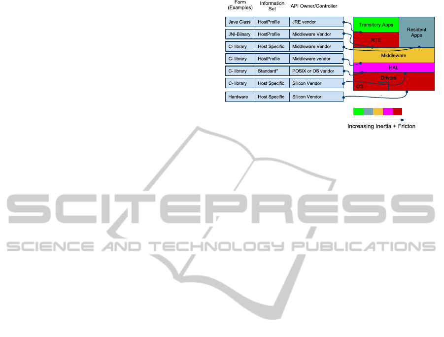
Procedural programming languages, particularly
C, allow for many styles of APIs to be defined. The
ratio of documented entropy and spurious hidden en-
tropy in an interface is related to the friction that
components have when joined by an interface. ‘Fric-
tion’ is used here to represent the ease with which a
change can be made to a component using the inter-
face. Causes of friction in an interface include (1) API
Form: The language or format it is expressed in. (2)
API Information Set: The information it must convey.
(3) API Controller: The owner of the interface with
authority to change it.
The efficiency with which modifications or re-
placement of components can be made is governed
by the API friction and also the internal inertia of the
component. Component ‘inertia’ is also dependent on
multiple factors including complexity, ownership and
CPU dependence.
An example system of components in a typical
Figure 1: Component inertia and interface friction illustra-
tion.
embedded device using a Java RTE, is described in
figure 1. The diagram illustrates a landscape of
changeability of components on the basis of the fric-
tion heuristics involved with its interfaces combined
with the component’s internal inertia heuristic.
The environment illustrates the example with a
JVM-based RTE implementation. The RTE has large
inertia as a result of complexity, CPU dependence
and ownership. The following illustration (figure 2)
is intended to aid identifying the cost landscape for
changes in system components. The y-axis is ar-
ranged (approximately) with components in increas-
ing order of inertia and friction when implemented
entirely with native software.
The cost function can therefore be envisaged qual-
itatively as a surface of increasing cost when travel-
ling North-East in figure 2. The term ‘cost’ here is
intended to include the general sense including: de-
velopment resource cost, development time and the
opportunity costs of not electing to carry out a bene-
ficial change. The areas outlined in green or orange
depict typical example areas of the landscape that can
be implemented using a non-native run-time environ-
ment such as Java or an HTML rendering engine.
In either case the size of the areas in the landscape
where an RTE could be substituted require careful
consideration with respect to the costs of integrating
and maintaining the RTE itself. The illustrated land-
scape indicates in this case that Java or browser-based
RTEs do not necessarily substitute parts of the system
associated with the highest costs when implemented
natively.
3.1 Towards an Ideal Integration
Structure
With the objective of providing replacements for na-
tive software that is more extensive in areas of higher
cost and also reduce the cost of maintaining the RTE
PECCS 2011 - International Conference on Pervasive and Embedded Computing and Communication Systems
244
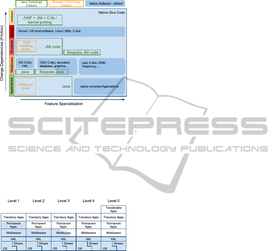
Figure 2: Illustration of Component Change Landscape.
.
code a new approach is presented. There is a strong
rationale for maintaining support for residual legacy
middleware components that must be accounted for.
These Residual components could progressively be
decoupled and reduced in scope by process of itera-
tive decomposition, but in practice such components
encapsulate a non-disposable amount of know-how
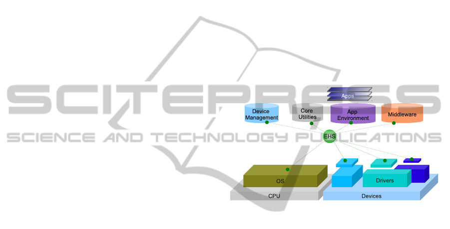
and bug-fixes. Figure 3 illustrates a progressive mi-
gration process that could be adopted to resolve such
issues in practical time-scales. The following charac-
Figure 3: Native component (shaded) residual roadmap.
teristics of the APIs in the system have been identified
to avoid burdens of the software integration environ-
ment
• R1.1. Component interfaces can be decoupled
from each other via an intermediate canonical API
that links to all components in such a way that
components do not require others to exist in the
environment at build time or run-time.
• R1.2. The call overhead of one component caus-
ing the another component to begin processing is
not significantly larger than if the function call
was carried out with native processing.
• R1.3. Data passing between components does
not require data transformation or other overheads
and includes the facility for data to be communi-
cated by typed reference.
• R1.4. The mapping of all processing events and
data that are receivable and assertable between
components is reconfigurable at load time of the
application language.
• R1.5. The RTE is not complex in terms of its
hardware dependencies (either direct or indirect)
to ensure its own mobility.
• R1.6. The API is sufficiently simple and complete
that changes to the interface are rarely needed (i.e.
it is canonical).
In order for applications to utilise the above operat-
ing environment, a language that enables the applica-
tion to be expressed without extraneous informationis
sought. The programming language should conform
to the following constraints:
• R2.1 Fully expressivein terms of performingstan-
dard functions and allowing formulation of algo-
rithms to achieve any other computable function.
• R2.2 Define responses to environmental events
and data with conditional and unconditional pro-
cessing sequences and asserting events and data
as a result.
• R2.3 Allow for concurrent processing of multiple
tasks and provide real-time precessing under op-
erational constraints.
• R2.4 Allow reference to all functional resources
and features available in the host device.
Ideal features of the environment would also include:
• R2.5 The programming environment is familiar to
a broad section of developers and is compatible
with well known design paradigms.
• R2.6 Able to synthesize applications from compo-
nents and decompose complexity into minimally
coupled modular units in the design environment.
A method to introduce a programming language into
a system with the above set of constraints is resolv-
able by taking a direct approach to addressing R1.4.
The device programming language, presented here,
is essentially configuration data that maps compo-
nents together, using a standard native function li-
braries (R2.1). The native function libraries are con-
structed to include the low level logical patterns re-
quired to create arbitrary logic and data manage-
ment (R2.2). The event-handling ontology implied by
(R1.4) provides the concurrent programming environ-
ment called for in (R2.3). Similarly (R2.4) is met by
the definition of (R1.4). The real-time requirements
specified in the programming language require addi-
tional meta-data provided with the event mapping to
UBIQUITOUS COMPUTING NEEDS UBIQUITOUS SOFTWARE - A General-Purpose Computation Model
245
basis functions that describes the resource allocations
available to each function instance.
There are a number of possibilities for addressing
R2.5 and R2.6, the most obvious is in representing the
mapping of events and components in a flow-based
model. Maintaining a simple relationship between the
device software and the system design environment
is compelling as this simplifies software build, de-
bugging and deployment processes. Simplifying the
software build process and avoiding the possibility of
syntactical problems using a simply defined language
that can be generated (robustly) in a design environ-
ment is a highly appealing feature.
4 IMPLEMENTATION METHODS
The device instruction ontology contains object ori-
ented elements to allow methods to share subsystem
states. Methods can then interconnect objects via a
data and event connection model referred to as the
System Object Description Language (SODL). The
topology of SODL can be represented most simply
using Yourdon type diagrams (Yourdon, 1989) with
real-time extensions (Ward and Mellor, 1985). Edges
in these diagrams represent event and data location
identifiers that form the mappings between objects.
The format of SODL is not complex in structure
and can be formatted as plain text, XML, or a struc-
tured binary form such as ASN.1. An object with a
single method defined in plain text SODL has the fol-
lowing form:
OBJECT <Object type identifier 1>
<Parameter Tuple>
<Function Name 1> <Processing Group ID>
<atomic flag> <start event ID>
<#data inputs> <input ID 1>
<#data outputs> <output ID 1>
<#event outputs> <event ID 1>
END
The component mappings are identified here simply
by enumeratedIDs that represent an event or data path
between functions. Each function belongs to an ob-
ject and each object is provided with initialisation data
specified by the application programmer. With this in-
formation the run-time environment, here named the
Event Handling System (EHS) has a relatively simple
job to do to execute the system:
• Provide dynamic binding data to native compo-
nent functions to allow them to access an array of
data locations specified in SODL.
• Provide a buffer for event IDs to be posted to and
from component functions
• Provide an algorithm to schedule further functions
to run within the required time and sequence con-
straints defined by referring to processing group
information and also using the prior information
provided by the <atomic flag> to identify if the
function is trusted to run as a cooperativelysched-
uled process to ensure optimal system efficiency.
The run-time environment can be targeted for differ-
ent architectures easily because of the simplicity and
independence to CPU types.
Figure 4 below represents how the run-time en-
vironment acts as a hub between native middleware
components, core component libraries, the device
drivers and operating system services. The bindings
Figure 4: Representation of the run-time Architecture.
of the component functions with the event handling
system are computationally very simple, adding few,
if any, additional clock cycles to a function call com-
pared to a best case direct function call using the
stack. Because the units of processing are much more
complex than machine or Virtual Machine byte code
the overhead of the architecture is minimised in any
case. The virtualisation technique is essentially im-
plemented as an extreme case SuperCISC computer.
The choice of programming environment to gen-
erates SODL code in this article is based on data
flow diagrams with real-time extensions as this re-
lates closely to the information contained in SODL.
Assigning unique IDs to event or data edges defined
in the the diagram formulates the tuples for each ba-
sis function and the events that cause them to run. The
combination of control and data flow in a single dia-
gram allows the design environment to easily struc-
ture software development by allowing for groups of
objects to be encapsulated into sub-systems that can
then be manipulated in the same way as the the basis
set of native components.
For event-driven applications, in particular, there
is great scope remaining in field of graphical design
PECCS 2011 - International Conference on Pervasive and Embedded Computing and Communication Systems
246

environments that could encompass a more complete
set of programming paradigms. Currently the en-
vironment includes object oriented design, graphical
debugging systems, complex data-typing and compo-
nent subsystem sharing between projects and devel-
opers. Formalising object inheritance of primitiveand
composed function blocks purely in the graphical do-
main is a further area of interest.
One particular advantage of maintaining a close
relationship between the programming environment
and the device instruction set as that this effectively
removes the ‘round-trip problem’ of code genera-
tion from graphical programming environments such
as UML. The current application programming tool
supports TCPIP communicate directly with the target
device during development phases, allowing transfer
programme data for fast round-trip development and
also supporting real-time graphical debugging of de-
vice behaviour.
5 IN-USE EVALUATION
The core EHS software, including a restricted stan-
dard component library, can operate on devices with
very low processing power, including for example 8-
bit devices with as little as 16KROM and 8K RAM.
Such device are not the initial target for the technol-
ogy, however this example is indicative of the mini-
mal system resources required for the RTE.EHS and
the full standard component toolkit have been built to
run on larger devices, typically utilising Linux, QNX,
Nucleus or Win32 operating systems. Target CPU ar-
chitectures tested include most variants of x86, MIPS,
SH4, PPC, and ARM.
The EHS device software, minus all component li-
brary source code, comprises ∼ 2000 lines of ANSI-C
(LOCs). Only 47 LOCs are specific to the target oper-
ating system and none are CPU specific. The standard
component library comprises ∼ 3700 LOCs and is en-
tirely hardware/OS independent, depending only on
ANSI-C. The total code size of the EHS and the com-
plete set of component library interfaces comprises ∼
6700 lines of independent code.
SODL file sizes scale approximately 100 bytes of
plain text (20bytes compressed) per component in-
stance. Application load times from flash memory
were invariably less than 1 second for an applica-
tion containing several 1000s of function blocks on
a 200MHz Vortex86 processor.
5.1 Component Integration
Components written entirely in ANSI-C without li-
brary dependencies were integrated into the compo-
nent modules, by importing the source into a compo-
nent module build system and generating the XML
API description file. The key aspect of this process
was in defining an easily usable functional interface
for the component.
LegacyAudio Visual components exemplify a dif-
ferent integration process, where typically the es-
tablished build complexity of the legacy component
suggests leveraging the pre-established build system.
Legacy components are typically buildable for differ-
ent targets as static or dynamic libraries and were inte-
grated with EHS by building wrappers that map their
pre-defined APIs to the generic EHS API. Wrappers
typically include an API state machine to ensure com-
ponents are not depend on client trust.
Taking an Audio Visual player component as an
example, the first step was to design a functional in-
terface from an application developer’s point of view,
that would ideally be common to different target’s
player APIs. A Hardware Abstraction Layer (HAL)
was then used to wrap target componentfunction calls
for the A/V subsystem, mapping these to the applica-
tion developer centric EHS A/V component API.
The first A/V target system integrated was based
on SoC specific native code where decoders and
graphics were hardware accelerated and drivers for
this were included in the integration. A second exam-
ple of integrating a more portable software-based A/V
decoder for x86, ARM and PPC processors was sub-
sequently evaluated using the same EHS A/V com-
ponent API. libVLC (Video LAN library) was used
for this purpose and was first built in its library form
using the autoconf build tree provided in the release.
Both the SoC and libVLC legacy software builds were
complex and hampered by sensitivity to dependency
versions and host build environment. Once libraries
were built for each target and linked to EHS, no fur-
ther effort was required to deal with these libraries
during subsequent component integration.
5.2 Application Development
It was identified at an early stage of using the devel-
opment environment that because the programming
environment is naturally concurrent the programmer
must use constructs to ensure synchronicity of data
and events along processing chains. The following
symbols exemplified two basic types of event han-
dling components, implemented as components that
need to be made available to the programmer to con-
trol event flow. The ease of programming was found
to be dependent on the details of defining standard
basis components for event and data management. A
UBIQUITOUS COMPUTING NEEDS UBIQUITOUS SOFTWARE - A General-Purpose Computation Model
247
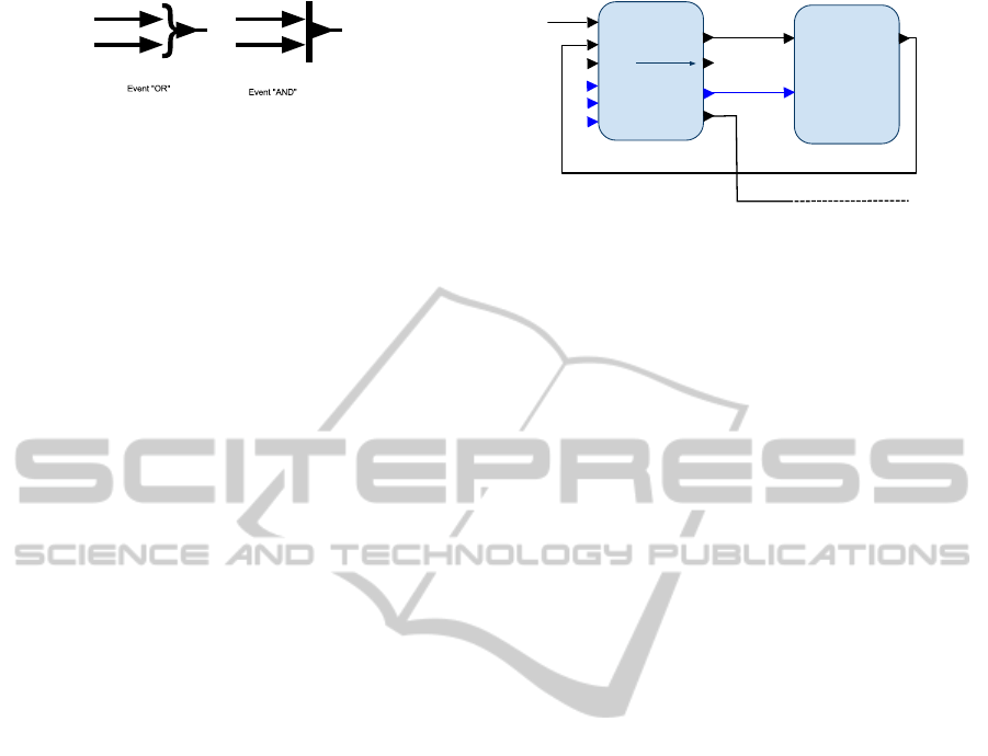
Figure 5: Event Handling Icons.
stable set of 20 types of core data and event handling
function blocks were devised that were sufficiently
complete and intuitive to use to build the logic for
all the applications tested. Some general rules were
observed when implementing any function block in-
terface that made function blocks easy to use in the
integration environment.
1. At least one output event should be asserted for
every input event to allow serialisation of process-
ing when required. If error conditions are possi-
ble, an error or specific condition event should be
generated even if the normal operation could not
be completed.
2. Iteration loop constructs such as ‘for’ should be
supported with familiar constructs instead of re-
using more primitive components such as coun-
ters.
3. Object parameters can be entered as static defaults
for each function block in the design environ-
ment and when appropriate these values should
be over-writable with dynamic values read from
input ports.
With these guidelines most event driven function
block-based applications required little in the way of
additional logic to define conditional control flow and
sequencing between functions. This is a consequence
of function blocks conditionally asserting events de-
pending on processing outcomes without any further
condition testing. There are situations where explicit
procedural types of constructs are required, such as
processing loops and branching. It was found that
providing more familiar looking representations of
standard procedural constructs, rather than relying on
more primitive components such as counters aided
most developers. For example the ‘for’ loop func-
tion block (figure 6) gives a direct representation of
the procedural construct.
In addition to the core toolkit a number of device
profiles were defined for peripheral components. Pro-
files allow different component modules such as Au-
dio/Visual, Networking, scripting and database to be
included or excluded from a target’s set of basis func-
tions.
For
One Iteration
Subsystem
start=1
Loop Complete
index
Iterator
Start
Next
Reset
Complete
stop=100
step=10
Do
Figure 6: Illustration of loop specific packaging of a counter
primitive.
6 CONCLUSIONS
The proposed device architecture was found to pro-
vide a great deal of agility in integrating new device
system software and in developing new applications.
With the exception of the complex A/V and some
graphics rendering technologies, the remaining native
components were integrated in time-scales of ranging
from a few hours to one or two days if the component
interface required significant additional functionality
to be useful. No manual steps were required in port-
ing the core EHS code to new targets indicating a low
level of inertia and friction for the EHS based RTE.
Large scale embedded software integration
projects have been effectively harnessed using EHS
as an embedded integration platform and the design
environment has been found powerfull enough to
orchestrate 1000s of function blocks in a hierarchical
designs without scaling problems. The integration
of complex proprietary set-top-box software stacks
demonstrated the homogeneity achievable with the
other target’s implementations. The application de-
velopment environment was found to be effective in
creating and debugging new applications to the level
of ease where transitory applications for set-top-box
targets such as the classic space invaders game was
built within 3 days of effort. Static automated media
players have also been implemented and remotely
maintained using the A/V profile, utilising a range of
different hardware and operating systems.
During development of these complex applica-
tions some weaknesses in the static object paradigm
where identified, which prompted the development of
function blocks that can produce dynamic instances
at run-time. A formal approach was then designed
that required a new native component module to be
introduced to aid the programmer in referencing and
iterating dynamically created object instances at run
time.
As a component developer the environment was
found to provide a useful framework for developing
new components in native code. The environment al-
PECCS 2011 - International Conference on Pervasive and Embedded Computing and Communication Systems
248

lowed test applications to be developed very rapidly
for the component and integrated into systems with-
out further code integration effort. The component
integration and application environment removed or
significantly reduced the many nuisance factors in-
volved in embedded software development such as
target download/test cycle times, build systems devel-
opment, hardware-debugging and automated system
test creation.
6.1 Future Work
Current work-in-progress is to address some of the
weaknesses identified in the development environ-
ment, particularly the implementation of dynamic ob-
ject handling. Also open source tools/IDE plugins for
graphically creating C-based EHS APIs are currently
in development. A more general open source release
of the tools and run-time is subsequently planned .
There are extensive opportunities to extend graph-
ical environments for use in systems integration and
application development. Particularly in regularising
complex data/event interfaces between components.
The topological origins of the application software
also lends itself to distributed processing, where the
design environment can separate multi-processor sub-
systems easily in the design and SODL domain. Some
initial proof of concept implementations have shown
that a publish and subscribe mechanism to export and
import missing data between deviceis a promising ap-
proach for implementing such systems.
The EHS run-time technology described is be-
lieved to provide a generalised computing platform
that can be used effectivelyorall but the smallest class
of CPUs. Furthermore EHS is not incompatible with
a wide range of hardware processor types including
ASICS, FPGAs and event driven hardware architec-
tures.
REFERENCES
Fielding, R. T. (2000). Architectural Styles and the Design
of Network-based Software Architectures. University
of California, Irvine, USA.
Google (2011). www.android.com.
Haddad, B. (2010). Introduction to the MeeGo Project. The
Linux Foundation.
Libby, J. C. and Kent, K. B. (2009). An embedded im-
plementation of the common language infrastructure.
Journal of System Architectures, 55:114–126.
Object Management Group (2011). Data distribution ser-
vice (DDS).
Ross, A. M., Rhodes, D. H., and Hastings, D. E. (2008).
Defining changeability: Reconciling flexibility, adapt-
ability, scalability, modifiability, and robustness for
maintaining system lifecycle value. Systems Engi-
neering, 11:246262.
van Ommering, R., van der Linden, F., Kramer, J., and
Magee, J. (2000). The koala component model
for consumer electronics software. IEEE Computer,
33(3):78–85.
Waldo, J. (1999). The jini architecture for network-centric
computing. Commun. ACM, 42(7):76–82.
Ward, P. T. and Mellor, S. J. (1985). Structured Develop-
ment for Real-time Systems (three volumes). Yourden
Press.
Yourdon, E. (1989). Modern Structured Analysis. Yourden
Press.
UBIQUITOUS COMPUTING NEEDS UBIQUITOUS SOFTWARE - A General-Purpose Computation Model
249
