
EFFICIENT SERIAL FLOATING-POINT CONSTANT DIVIDER
STRUCTURE OF THE FORM 2
P
±1
Karthik Mahesh Varadarajan
ACIN, Technical University of Vienna, Vienna, Austria
Keywords: Constant divider circuit, Integer division, Serial division, Full-precision division, DSP, VLSI,
Computational optimization.
Abstract: Implementation specific computation modules hold the key to the success of fast DSP and Embedded
systems. Exponential encoders, dedicated multipliers, barrel shifters and accumulators are common units
available on DSPs. The family of constant divider circuits of the form 2
p
±1, which are useful for image
processing, statistical processing like histograms etc., is the specific focus of this paper. This family is
largely dominated by the Residue Number System (RNS), Petry and Srinivasan algorithms and the Shuo-
Yen Robert-Li algorithm. While these algorithms offer various trade-offs in terms of accuracy, memory
footprint, power consumption and timing behavior, none of these methods are suited for processing
serialized inputs, dividend inputs with apriori unknown bit length and the circuits have to be replaced with
change in input bit length. The circuit size also grows enormously for large input lengths along with a
reduction in accuracy. These methods are suited only for integer division and are unsuited for extension to
floating/fixed point division. In this paper a novel constant divider algorithm is offered, which overcomes
the above mentioned limitations while handling arbitrary length, serial/ parallel data and producing full-
precision, full-accuracy, floating point capable results with constant circuit requirements and comparable
timing to state of the art methods.
1 INTRODUCTION
Software and hardware optimization processes are
essential elements towards building a cost-effective
and efficient embedded system. Dedicated
computation modules hold the key to the success of
fast DSP, GPU and Embedded systems. Modern
DSP development and deployment kits host a
number of dedicated computation units. Exponential
encoders, dedicated multipliers, barrel shifters and
accumulators are common units available on DSPs.
One specific computation module that holds
considerable importance with respect to embedded
systems designed for signal and image processing
applications is the constant division operation. The
family of constant divider circuits of the form 2
p
±1
is the specific focus of this paper.
This computational module is useful for image
processing applications (such as division by image
dimensions or array lengths or extreme image
intensity values – typically represented as 2
p
-1),
signal processing (such as Fourier Transform
normalization), statistical processing like histogram
estimation etc. Division by 2
p
-1 also assumes
significance due to the fact that division by any
integer can be converted to that format using the
Euler-Fermat theorem.
2 RELATED WORK
The state of the art with respect to this family of
constant division by 2
p
±1 includes the Residue
Number System (RNS) (Al-Besher, 1997), Petry and
Srinivasan algorithms (Srinivasan, 2007) (Petry,
1994) (Petry, 1983) and the Shuo-Yen Robert-Li
algorithm (Li, 1985). While these algorithms offer
various trade-offs in terms of accuracy, memory
footprint, power consumption and timing behavior
(extensive comparisons are presented in
(Schwarzbacher, 2000) and (Srinivasan, 2007)),
none of these methods are suited for processing
serialized inputs, dividend inputs with apriori
unknown bit length and the circuits have to be
replaced with change in input bit length. In other
words, once a circuit has been designed for a certain
485
Varadarajan K..
EFFICIENT SERIAL FLOATING-POINT CONSTANT DIVIDER STRUCTURE OF THE FORM 2P±1.
DOI: 10.5220/0003402904850490
In Proceedings of the 1st International Conference on Pervasive and Embedded Computing and Communication Systems (PECCS-2011), pages
485-490
ISBN: 978-989-8425-48-5
Copyright
c
2011 SCITEPRESS (Science and Technology Publications, Lda.)
input bit stream size, the circuit has to be modified
in order to support longer bit streams. Also, these
circuits cannot produce partial or serialized results
and require the entire input data to be available
before performing the division operation. The
quotient and remainder are estimated using a shift,
add/subtract and scale paradigm resulting from
inverting the divisor in the binary format.
Alternatively, the division can be represented as a
multiplication (or shift and add) with a pre-scaling
operation. While some of the methods such as (Guei,
1985) compute the quotient bits from higher order to
lower order, methods such as (Artzy, 1974) compute
it in the reverse order. Methods such as (Petry, 1994)
do not give out an explicit remainder. Certain
methods are also restricted to exact divisions.
In addition to these constraints, the circuit size
for the implementation of most of these algorithms
also grows enormously for large input lengths along
with a reduction in accuracy and increase in
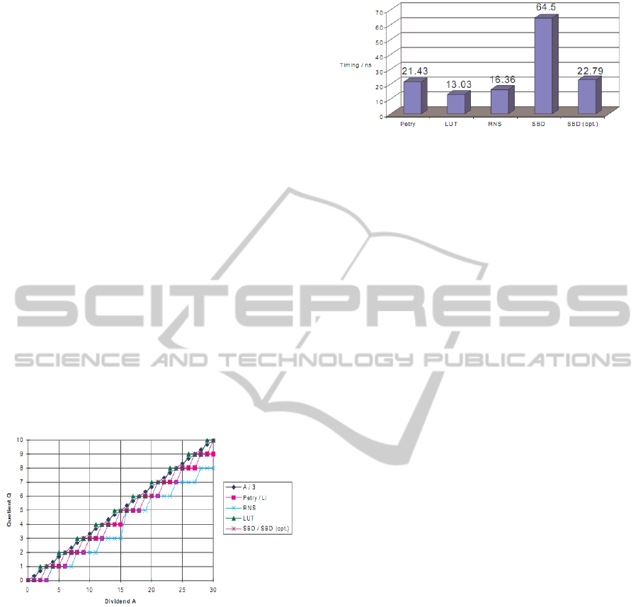
processing time (Figure 1 and 2). The addition of a
single tuple of dividend bits demands a circuit
change requiring an additional shifter and adder at
the very least. Moreover, these methods are suited
only for integer division and are unsuited for
extension to floating/fixed point division.
Figure 1: Accuracy and error deviation of different
approaches for a divide-by-3 operation (Src:
Schwarzbacher, 2000).
3 CONSTANT DIVIDER
ALGORITHM
In this paper a novel constant divider algorithm is
offered, which overcomes the limitations of the
previous algorithms, while handling arbitrary length,
serial/ parallel data and producing full-precision,
full-accuracy, floating point capable results with
constant circuit requirements and comparable timing
to state of the art methods.
Figure 2: Timing behavior of different approaches
obtained on European Silicon Structures 0.7µ CMOS
technology (Src: Schwarzbacher, 2000).
Two specific streams of processing are employed
for the cases of 2
p
-1 and 2
p
+1. These are described
in Figure 3 and Figure 4 respectively.
3.1 Division by 2
p
-1
The pseudo-code for the case of 2
p
-1 is detailed
below.
Step 1: Segment dividend into p-bit tuples
Step 2: Load T
n
into register 1, T
n-1
into register 2
Step 3: Add register 1 and 2
Step 4: If Sum >= 2
p
-1
Quotient tuple = register 1 + 1;
Remainder tuple = Sum – (2
p
-1);
Else
Quotient tuple = register 1;
Remainder tuple = Sum;
Step 5: Save quotient tuple in output buffer
Step 6: Load remainder tuple into register 1, next
dividend tuple (T
n-k
) into register 2
Step 7: Continue to Step 4, unless there are no
dividend tuples left
Step 8: Output partial remainder as remainder (for
integer division) or repeat partial remainder tuple
(for floating point division)
For the case of division by 2
p
-1, the input data
stream is divided into tuples of equal bit length ‘p’.
Zero padding is carried out, if necessary to
regularize the Most Significant Tuple (MST) to the
tuple size (p) being used. For the case of serial data
streams, this regularization may not be necessary, if
the serial input stream has been pre-synchronized for
the required tuple size. In Figure 3, it has been
assumed that for a tuple size of ‘p’ bits and input
dividend data stream length of ‘N’ bits, the number
of tuples generated is ‘n’. For the generation of the
most significant quotient tuple (represented by t=0 in
Figure 3), the MST (T
n
) of the dividend and the
second most significant tuple (T
n-1
) are loaded to
registers 1 and 2 respectively. A p-bit adder
calculates the sum of the two tuples. For the case of
an overflow – i.e. the carry bit being set, it is
PECCS 2011 - International Conference on Pervasive and Embedded Computing and Communication Systems
486
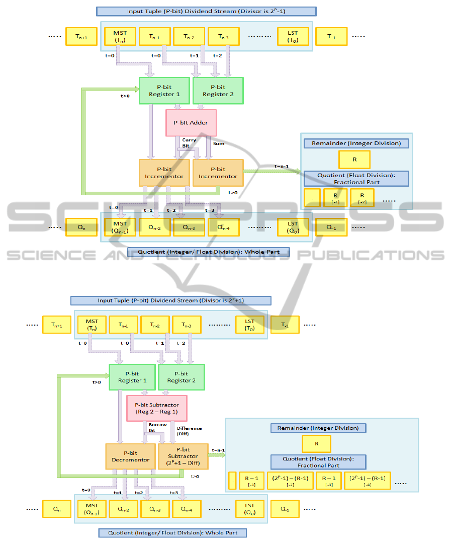
Figure 3: Functional units of the proposed 2
p
-1 constant divider circuit.
Figure 4: Functional units of the proposed 2
p
+1 constant divider circuit.
necessary to increment the contents of register 1 in
order to obtain the MST of the quotient. This is done
by connecting the activation port of the incrementor
to the carry bit. The incrementor is a functional unit
that increments the contents of a register by 1. It can
possibly be implemented using a simple adder
circuit or a counter. The MST of the quotient (Q
n-1
)
thus generated can be stored in a quotient buffer or
serialized for an output data stream. The sum output
from the p-bit adder forms the partial remainder.
EFFICIENT SERIAL FLOATING-POINT CONSTANT DIVIDER STRUCTURE OF THE FORM 2P±1
487

Similar to the quotient tuple, the partial
remainder has to be corrected in the case of a
generated carry. A second incrementor with the
activation port tied to the carry bit output of the
adder is used to obtain the partial remainder from the
generated sum tuple. For successive time sample
instances (t > 0), the partial remainder is loaded into
register 1 for the calculation of successive tuples of
the quotient. At these instances (t > 0), higher order
tuples (T
n-2
, T
n-3
, T
n-4
, T
n-5
..... etc.) are progressively
loaded into register 2. The adder then outputs the
partial quotient and remainder for each time instant.
The incrementor normalizes the partial quotient and
the remainder which are fed to the output queue and
to register 1 for the processing of the next sample
instant, respectively. The cycle generates the
quotient tuple bits for the whole part (non-fractional)
part in the case of both integer and floating point
division.
The processing is terminated when all the input
dividend tuples have been processed. In the case of
integer division, the process remainder equals the
partial remainder obtained from the second
incrementor for the last time sequence instant (t = n-
1). In the case of floating point division the
fractional part of the quotient is obtained as non-
terminating, recurring tuple bits computed by
repeating the tuple bits representing the partial
remainder. The fractional tuples can be generated to
any length based on the required levels of system
accuracy and precision. While this computation is
not very straightforward for the case of division by
2
p
+1, we present an alternate scheme to tackle this
issue, as demonstrated in the next section.
Computation of the fractional part is a major
advantage of the scheme presented in this paper and
unlike Petry and Srinivas or RNS, full accuracy can
be maintained to any desired precision.
3.2 Division by 2
p
+1
The pseudo-code for the case of 2
p
+1 is detailed
below.
Step 1: Segment dividend into p-bit tuples
Step 2: Load T
n
into register 1, T
n-1
into register 2
Step 3: Subtract register 1 from 2
Step 4: If Difference >= 0
Quotient tuple = register 1;
Remainder tuple = Difference;
Else
Quotient tuple = register 1 - 1;
Remainder tuple=Difference+(2
p
+1);
Step 5: Save quotient tuple in output buffer
Step 6: Load remainder tuple into register 1, next
dividend tuple (T
n-k
) into register 2
Step 7: Continue to Step 4, unless there are no
dividend tuples left
Step 8: Output partial remainder as remainder (for
integer division) or repeat partial remainder less 1
and its 2
p
-1 complement tuple (for floating point
division)
For the case of division by 2
p
+1, the input data
stream is similarly divided into tuples of equal bit
length ‘p’. Again, zero padding is carried out, if
necessary to regularize the Most Significant Tuple
(MST) to the tuple size (p) being used. In Figure 4, it
has been assumed that for a tuple size of ‘p’ bits and
input dividend data stream length of ‘N’ bits, the
number of tuples generated is ‘n’. Similar to the case
of division by 2
p
-1, for the generation of the most
significant quotient tuple (represented by t=0 in
Figure 4), the MST (T
n
) of the dividend and the
second most significant tuple (T
n-1
) are loaded to
registers 1 and 2 respectively. A p-bit subtractor
calculates the difference of the two tuples (register 2
– register 1). The subtractor can be implemented
using a 2’s complement logical adder. This also
helps obtain the correct difference between the two
tuples (the value being the absolute difference
between the two tuples along with a negative sign,
indicated by the borrow/overflow bit, for the case
when the value in register 2 is smaller than that in
register 1). In this case, i.e. the overflow or borrow
bit being set, it is necessary to decrement the
contents of register 1 in order to obtain the MST of
the quotient. This is done by connecting the
activation port of the decrementor to the borrow bit.
The decrementor is a functional unit that decrements
the contents of a register by 1. It can possibly be
implemented using a simple subtractor circuit or a
counter. Again, similar to the case of division by 2
p
-
1, the MST of the quotient (Q
n-1
) thus generated can
be stored in a quotient buffer or serialized for an
output data stream. The difference output from the
p-bit subtractor forms the partial remainder.
The partial remainder also has to be corrected
in the case of a generated borrow. A p-bit subtractor
(or alternatively a bit reversal module) with the
activation port tied to the borrow bit output of the
subtractor is used to obtain the partial remainder
from the generated sum tuple. The subtractor
computes the value of 2
p
+1 – Diff. Note that the
‘Diff’ quantity used here is the absolute difference
value between the two registers and hence the need
for the additional negative sign. For successive time
sample instances (t > 0), the partial remainder is
loaded into register 1 for the calculation of
PECCS 2011 - International Conference on Pervasive and Embedded Computing and Communication Systems
488

successive tuples of the quotient. As before, at these
instances (t > 0), higher order tuples (T
n-2
, T
n-3
, T
n-4
,
T
n-5
..... etc.) are progressively loaded into register 2.
The subtractor then outputs the partial quotient and
remainder for each time instant, while the
decrementor and the second subtractor normalize the
partial quotient and the remainder which are fed to
the output queue and to register 1 for the processing
of the next sample instant, respectively. The cycle
generates the quotient tuple bits for the whole part
(non-fractional) part in the case of both integer and
floating point division.
The processing is terminated when all the input
dividend tuples have been processed. In the case of
integer division, the process remainder equals the
partial remainder obtained from the second
subtractor for the last time sequence instant (t = n-1).
In the case of floating point division, the fractional
part of the quotient is obtained as non-terminating,
recurring tuple bits computed by repeating the tuple
bits representing the partial remainder less 1 and its
2
p
-1 complement. In other words the fraction part
consists of repeating sets of 2 tuples, the first of
which is one less than the partial remainder (R – 1)
and the second tuple is (2
P
-1) – (R-1).
As before, the fractional tuples can be
generated to any length based on the required levels
of system accuracy and precision.
4 ANALYSIS
Numerically, the algorithm presented in this paper
has an analogue in (Guei, 1985). However, unlike
the (Guei, 1985) algorithm which requires the entire
input stream for the computation, our scheme
requires only two tuples at any time sequence
instant, giving out one tuple of quotient bits along
with the partial remainder, based on carry/ borrow
calculation. Thus, our algorithm is well suited for
serial processing. Moreover, the circuit requirements
are constant for varying input bit lengths.
Additionally, our algorithm is well suited for integer
as well as floating point divisions and can generate
fractional results with arbitrary accuracy/ precision.
Since tuples can be processed serially using a
single adder and 2 incrementors (example case of
division by 2
P
-1), the constant circuit can be
efficiently implemented in hardware. As noted
earlier, the requirements do not change with increase
in input bit length and the same circuit can be
replicated for operation in parallel mode, in which
case the number of such computation units will be
equal to n – 1. Also, the design provides a natural
way to trade-off speed and circuit requirements
through the possibility of using a serial mode of
operation working on multiple tuples (or parallel
tuples) at the same time.
The possibility of calculating the fractional part
of the quotient to any arbitrary length with full
accuracy supports the use of the algorithm for
constant divider circuits in DSPs and other
embedded systems.
Since the number of computational units in the
pipeline is less than or is at least comparable to other
state-of-art methods, it can be expected that the
computational time numbers also favor use of our
approach.
5 CONCLUSIONS
AND FUTURE WORK
In this paper, we have presented the design for a
constant divider circuit of the form of the form 2
p
±1.
Analyses have also been presented to demonstrate
the constant computation requirements of the
approach. The method is well suited for processing
serialized inputs, dividend inputs with apriori
unknown bit length while producing full-precision,
full-accuracy, floating point capable results. The
next step would be to implement the design using
VHDL/Verilog for simulation and testing followed
by actual implementation in VLSI for a thorough
evaluation of timing, power requirements, memory
footprint and chip area estimation. This is expected
to be followed by performance evaluation of the
circuitry in consonance with a DSP or Embedded
System or a GPU targeted at applications such as
image processing, signal processing and statistical/
mathematical computation and modeling.
REFERENCES
A. Th. Schwarzbacher, M. Brutscheck, O. Schwingel, J. B.
Foley, ‘Constant Divider Structures of the Form 2
n
±1’, pp. 368-375, Irish Signals And Systems
Conference, 2000.
P. Srinivasan, F. E. Petry, ‘Constant-Division Algorithms’,
IEEE Proc. Computers and Digital Techniques, Vol.
141, No. 6, 2007 (1994).
A. Th. Schwarzbacher, P. A. Comiskey and J. B. Foley,
‘Reduction of the power consumption at the
algorithmic level of CMOS circuits’, Electronic
Systems and Devices Conference, pp. 5-8, June 1998.
B. Al-Besher, A. Bouridane, A. S. Ashur, ‘An RNS-based
Division Architecture for Constant Divisors of the
EFFICIENT SERIAL FLOATING-POINT CONSTANT DIVIDER STRUCTURE OF THE FORM 2P±1
489

Form 2
n
+1 and 2
n
-1’, Irish Signals & Systems
Conference, 1997.
S. Y. R. Li, ‘Fast Constant Division Routines,’ IEEE
Transactions on Computers, Vol. C-34, No. 9,
September 1985.
F. E. Petry, P. Srinivasan, ‘Division Techniques for
Integers of the Form 2
n
+1 and 2
n
-1’, Int. J.
Electronics, Vol. 74, No. 5, 1993.
R. L. Sites, ‘Serial Binary Division by Ten’, IEEE
Transactions on Computers, vol. 23, no. 12, pp. 1299-
1301, 1974.
Artzy, E., Hinds, J. A., Saal, H. J., 'A fast division
technique for constant divisors', Comm. ACM,
February 1976, 19, (Z), pp. 98-101.
C. Y. Guei, Y. X. Dong, W. B. Shan, 'A fast division
technique for constant divisors 2
m
(2
n
+/- 1)’,
Proceedings of the 1st International Conference on
Computers and Applications, 1985, pp. 715-718.
Johannes, J., Pegden, C., Petry, F., 'Decimal shifting for an
exact floating point representation', Computer and
Electrical Engineering, 1980.7, (3). pp. 149-155.
Petry, F. E., 'Two's complement extension of a parallel
binary division by ten', Electronics Letters, September
1983, 19, (18), pp. 718-720.
PECCS 2011 - International Conference on Pervasive and Embedded Computing and Communication Systems
490
