
AUXILIARY STORAGE AND DYNAMIC CONFIGURATION
FOR OPEN CLOUD STORAGE
Jincai Chen, Yangfeng Huang, Minghui Lai and Ping Lu
College of Computer Science and Technology, Wuhan National Laboratory for Optoelectronics
Huazhong University of Science and Technology, Wuhan, 430074, China
Keywords: Cloud Storage, Two-Tier Proxy, Auxiliary Storage, Dynamic Configuration.
Abstract: Along with the rapid development of cloud computing, cloud storage is also gradually warming. More and
more users and corporations are planning to use cloud storage services. At present, however, cloud storage
service technology is still facing many problems. Firstly, the current cloud storage systems only belong to
some specific cloud storage services providers and are enclosed to other cloud storage services providers.
Secondly, the growth of network transmission speed is relatively slow, which is difficult to transfer large
amounts of data in a given time. Finally, the current underlying storage architecture of cloud storage can not
be dynamically configured as required. For this reason, this paper presents an open architecture model of
cloud storage, which allows users to choose suitable cloud storage providers through the two-tier proxy. The
system can effectively reduce the response time of the users’ requests through using the geographic distribu-
tion auxiliary storage nodes to store hotspot data. The underlying storage architecture of data storage centers
can simultaneously adopt the Master-Slave architecture and the P2P architecture, which can hence own the
advantages of both two architectures.
1 INTRODUCTION
Nowadays along with the development of cloud
storage technology, service as you need and pay as
you go make more and more people consider using
cloud storage services. And there are also much re-
search which is related to cloud storage, such as en-
ergy consumption (Harnik .etc), storage architecture
(Abu-Libdeh.etc, 2010, Bowers.etc, 2009) and so on.
However, if we want cloud storage service to be
completely adopted, there are still many problems
which need to be solved. The detail as follows,
The existing cloud storage systems are still using
an enclosed structure, which can only support data
storage services offered by the particular cloud stor-
age services provider (CSSP). Moreover, data re-
sources cannot be reliably exchanged and shared
among various CSSPs.
The traditional network storage usually adopts
the communication mode that users directly com-
municate with data centers. This method is feasible
when the number of users is less and the volume of
data is small. However, the number of users in cloud
storage system is increasing quickly and the growth
of network transmission speed is relatively slow, the
response time of user requests will be very long and
the cloud storage service quality will be influenced.
To date, the typical architectures of cloud storage
is divided into two kinds. One is Master-Slave stor-
age architecture, such as Google file system. (Ghe-
mawat.etc,2003). The mainly advantages of this in-
clude the convenient system maintenance and the
easy synchronization and updates of data. The other
is P2P storage architecture, e.g. Amazon’s Dynamo.
(Decandia.etc, 2007). The major advantages of this
contain much less hotspot data and without single
point failure and so on. So far there is no such a
cloud storage system which can own the advantages
of both two architectures.
In this work, we present a cloud storage architec-
ture, which can effectively solve the current prob-
lems of cloud storage. The contributions of this pa-
per are:
(1) We present a cloud storage architecture
model, which make the cloud storage architecture
open through the two-tier proxy so that users can use
cloud storage service provided by multiple CSSPs.
(2) We assign multiple ASNs in which the hot-
spot data stored around the DSC so that the system
520
Chen J., Huang Y., Lai M. and Lu P..
AUXILIARY STORAGE AND DYNAMIC CONFIGURATION FOR OPEN CLOUD STORAGE.
DOI: 10.5220/0003390705200524
In Proceedings of the 1st International Conference on Cloud Computing and Services Science (CLOSER-2011), pages 520-524
ISBN: 978-989-8425-52-2
Copyright
c
2011 SCITEPRESS (Science and Technology Publications, Lda.)
can effectively reduce the response time of the user’
request and perceive change of user environment.
(3) We present an underlying storage architecture
which can own the advantages of both the P2P stor-
age architecture and the Master-Slave architecture.
This new storage architecture can be dynamically
configured.
The remainder of the paper is organized as fol-
lows: in Section 2, we consider the scope of cloud
storage architectures and propose a comprehensive
framework; In Section 3, we analyze consistency of
the cloud storage; In Section 4, we discuss some
migration issues; Finally, we summarize our find-
ings and outline directions for future work.
2 THE CLOUD STORAGE
ARCHITECTURE
In this section, we will mainly expound the cloud
storage architecture model. This model has several
primary features: (a) Make cloud storage an open
architecture model by using the two-tier proxy. (b)
Reduce the response time of user’ requests and per-
ceive the changes of user environment by the use of
ASNs. (c) Adjust the underlying storage infrastuc-
ture dynamically according to the system demand.
2.1 Two-Tier Proxy
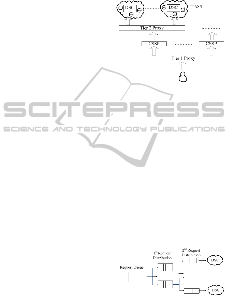
2.1.1 Selection of CSSP and DSC
This cloud storage system is designed to be open,
and will no longer be confined to a particular CSSP
and specific DSC. As shown in Figure 1, users select
the CSSP through Tier 1 proxy nodes, and choose
the suitable DSC which belongs to certain CSSP
through Tier 2 proxy nodes.
Tier 1 proxy node, which do not belong to any
specific CSSP, is managed by neutral institutions,
such as government departments. Tier 1 proxy nodes
contain all the information of each CSSP, such as
capacity, storage cost, access speed and credit and so
on, and select the appropriate Tier 2 proxy according
to the cheaper cost or faster speed and so on. In ad-
dition, Tier 1 proxy nodes also need to store users’
account information, such as username, password,
and record that is the corresponding relationship
between the data and the CSSP, etc. Compared with
the current account information which is stored in a
particular CSSP, it is stored in a neutral body will be
more secure. In order to avoid heavy load in Tier 1
proxy nodes, they just store these two kinds of data.
Figure 1: Two-Tier Proxy.
Data information stored in each Tier 1 proxy
node is the same. Tier 1 proxy nodes receive user-
name, password and other information submitted by
users, and then connect to the Tier 2 proxy nodes
which link with each CSSP storing the user’s data.
Tier 1 proxy nodes respectively generate a user
name and a password for each CSSP which provide
storage services for user.
Tier 2 proxy nodes, which belong to some par-
ticular CSSP, store various information relevant to
DSC, such as geographical position, bandwidth, ex-
pense, DSC in which data are stored, some account
information including username and password
automatically generated by Tier 1 proxy nodes, and
so on. Besides, It also select the suitable DSC ac-
cording to the position or bandwidth and so on.
After using two-tier proxy, though CSSP have
username and password, they still do not know who
the data belong to, thus it greatly improve the safety.
When users log in Tier 1 proxy nodes through a
browser, Tier 1 proxy nodes display all the relevant
information such as which CSSP data are stored in,
how much data are stored separately, how much to
spend respectively, and other information. The user
can manipulate the data later.
……
……
……
Figure 2: Requests Distribution.
AUXILIARY STORAGE AND DYNAMIC CONFIGURATION FOR OPEN CLOUD STORAGE
521

2.1.2 Requests Distribution
Another effect of this two-tier proxy is the distribu-
tion of users’ requests. As shown in Figure 2. When
the load of a Tier 1 proxy node exceeds a certain
threshold, part of users’ requests is forwarded to
other Tier 1 proxy nodes to make the load of this
Tier 1 proxy node return to the normal level. This is
the first request distribution. The second request
distribution of Tier 2 proxy nodes also like this.
2.2 Auxiliary Storage Node (ASN)
2.2.1 Response Time
As shown in Figure 3, each CSSP has many DSCs
which are distributed around the world. In each
DSC, there are a number of ASNs. These deployed
around the DSC consist of the geographic distribu-
tion of small storage network.
ASNs store users’ data that is the use frequency
which exceeds a certain threshold, namely the hot-
spot data, one replication of which is stored in the
ASNs and other ones of which are stored in the
DSC. Threshold can be dynamically adjusted ac-
cording to the use of the capacity of ASN, not to
such an extent as to waste storage space for less data
stored.
To choose ASNs for DSC, it mainly consider
about the location, access speed, load, and several
other aspects. Hotspot data can be stored in the near-
est ASN away from the owner of the data or lighter
load ASNs. Furthermore, under the long tail theory,
in the most time users are using a small part of the
data, thus most of the data are particularly rarely
used. As a result, there is no need to interconnect
with DSC dealing with hotspot data, which can be
processed directly in the ASN. If so, it will greatly
improve the response time of users’ requests, and
reduce the load on the DSC. The difference from the
DSC
ASN
ASN
Figure 3: The Relationship of DSC and ASN.
CDN is that users’ hotspot data is stored in ASNs
and which can be dynamically changed as the envi-
ronment and requirement of users.
2.2.2 User-aware
Setting the ASNs to reduce the response time of us-
ers’ requests, this is in terms of the specific envi-
ronment for the user. DSC should be able to make
corresponding adjustment according to the user en-
vironment changes. For example, user U located in
P1 often uses hotspot data D1 stored in ASN A1, but
when user U moves to P2, the hotspot data used is
likely D2. In addition, even if the hotspot data D1
have not been changed, the ASN A1 may also be
inappropriate due to the geographic environment.
Therefore, the DSC should be able to sense the
changes of the user environment, and select the most
appropriate ASNs for storage of hotspot data in or-
der to achieve faster response time and reduce the
load of the DSC.
2.2.3 Security
Besides, in order to avoid data being deleted due to
misoperation, when the data waiting to be removed
is stored in ASNs, if the user sends a deletion re-
quest, this data which is stored in ASNs are deleted
and all replications stored in DSC are deleted except
for one. Then the user sets a deadline for the remain-
ing copy, only when the deadline has expired, the
user data can be removed. It aims to facilitate users
to quickly recover those data frequently used.
2.3 Dynamic Configuration of
Underlying Storage Infrastructure
2.3.1 Mechanism of Dynamic Configuration
To date, it has not been reported in the publication
that there is a cloud storage system, which can use
Master-Slave and P2P structures. The underlying
storage architecture designed in this paper will be
able to simultaneously adopt both structures and
dynamically adjust according to the system configu-
ration parameters.
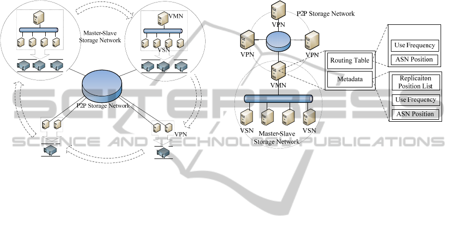
As Figure 4 shows, the Master-Slave storage
network as a whole is added to P2P storage network,
and all of the storage nodes are virtual nodes in the
DSCs. These virtual nodes are abstract nodes which
are formed by deploying virtualization software
(such as XEN (Barham.etc, 2003)) in the physical
nodes. It aims at obtaining better scalability, good
isolation, and easy migration. When the system
boots, (1) Get configuration information from the
CLOSER 2011 - International Conference on Cloud Computing and Services Science
522
configuration file firstly, and then configure virtual
nodes with no need for configuring their structure to
Master-Slave to P2P storage network. (2) Secondly,
set some of the remaining nodes to be one storage
network with Master-Slave structure or more. (3)
Finally, join Master-Slave storage network(s) into
P2P storage network. P2P storage network can be
structured by virtual nodes or Master-Slave storage
network respectively, or by the both.
Figure 4: Master-Slave Storage Network and P2P storage
Network.
2.3.2 Routing Table and Metadata
As Figure 4 shows, the Master-Slave storage net-
work is composed by virtual management node
(VMN) and virtual storage nodes (VSNs). VMN
stores metadata information, while VSNs store user
data. In P2P storage network, all the nodes are vir-
tual p2p nodes (VPNs), which save routing table
information and user data. Figure 5 is a structure
schematic drawing of metadata and routing table.
In P2P storage networks, the routing table in or-
dinary VPNs has some location and routing informa-
tion, besides, it still contains two fields, respectively
use frequency and ASN position information. The
routing table in P2P storage networks is used to
route and locate VPN which stores the data. Use
frequency is to point out the number of using this
block of data in certain period. In the routing table
the ASNs’ location information fields record the
relationship between the hotspot data and the ASNs.
Use frequency and ASNs’ positional information of
routing table is for VPNs of P2P storage network
concerned.
In the Master-Slave storage network, a VMN is
also as a VPN. A VMN not only contains routing
table, but also includes metadata information, which
contains the frequency of utilization, ASNs’ location
information and the list of replications’ position in-
formation. Different from the use frequency and
ASN’s location information in the routing table,
these in the metadata informations aim at VSNs in
the Master-Slave storage network. The lists of repli-
cations’ location information are used to record the
position of each replication. All copies of the same
data may have been stored in the VSNs, and some
may be stored in the VPNs.
……
Figure 5: The Structure of Routing Table and Metadata.
Besides, according to CAP theory, consistency,
availability and network partition can not simultane-
ously satisfy. In order to have better availability and
avoid network partition, the consistency of P2P and
Master-Slave storage network between each copy
employs eventually consistent.
3 CONSISTENCY OF ASN
AND DSC
Addition: When DSC receives the user’s addition
request, the system will connect with ASN of the
DSC and make a comprehensive assessment from
the load, storage capacity and access speed to find
the most appropriate ASN to storage new data. After
choosing the most appropriate ASN, the system will
compare it with the DSC to determine where the
new data should be stored. If the data are stored in
the ASN, The ASN needs to make a temporary
backup for the data. After the addition operation
have finished, the ASN send a message to the corre-
sponding DSC. The DSC adds the metadata of this
data, and modifies the location information of ASN
and other related content. The ASN will do data
synchronization with DSC after a moment and delete
the temporary backup. After a period of time, if use
frequency of this data has not achieved the system
setting threshold, the DSC will notify the ASN to
AUXILIARY STORAGE AND DYNAMIC CONFIGURATION FOR OPEN CLOUD STORAGE
523

delete the data and modify the ASN’s location in-
formation.
Update: When users need to update their data, they
send their update command to the DSC. If the data
that need to be updated are stored in the ASN, the
system will compare the ASN with the DSC. If the
load of the DSC is lighter, the DSC will deal with
the update request. Otherwise, the ASN will do it.
After the ASN modify the data, it should update the
use frequency of the data in the DSC. Then the data
synchronization will happen between the ASN and
the DSC. Whether or not the data modification op-
eration happens in the ASN or DSC, the system will
check the metadata of the data according to the pre-
set strategies.
4 VMS MIGRATION
When the DSC adjusts the underlying storage archi-
tecture, data migration has two kinds, one is data
migrate from P2P storage network to Master-Slave
storage network, the other is contrary. For the first
kinds, when a common VPN needs to migrate to
Master-Slave storage network, the node only needs
to exit the P2P storage network and join the Master-
Slave storage network as a new node. Then the
VMN of the corresponding Master-Slave storage
network updates the related metadata information of
each data block in the migrated node and the meta-
data of the use frequency and the location informa-
tion of the ASN will be reserved in the virtual man-
agement node. The system will delete the original
routing table of this node which is used in the P2P
storage network, but the data information of users
will not be deleted. So these data can be visited both
from the P2P storage network and the Master-Slave
storage network. For the second kinds, when the
VSNs of the Master-Slave storage network needs to
migrate to the P2P storage network, the node only
needs to exit the Master-Slave storage network and
join the P2P storage network as a new node. Then
the system will initialize the routing table. Besides,
the use frequency and the ASN’s location informa-
tion in the metadata will be copied into this route
table from the VMN.
5 CONCLUSIONS
The main research content of this paper is that we
have presented a open cloud storage architecture
model which can dynamically configure the underly-
ing storage architecture and process the hotspot data
through ASNs. At last, We have discussed the con-
sistency and migration problems of cloud storage
system.
For the future work, we plan to research our pro-
posed architecture in the following two ways, (1)
building the model of the ASNs and simulating with
Cloudsim (Buyya.etc, 2009) and neural network, and
(2) building the model of the underlying storage
architecture and simulating through the P2P simula-
tion tools such as P2Psim (Montresor.etc, 2009).
ACKNOWLEDGEMENTS
We thank Mrs. Ning Wang and Mr. Ming Chen for
their helpful discussions. This work was supported
by the National High-Tech Research and Develop-
ment Plan of China under Grant No.2009AA01A402,
the Natural Science Foundation of Hubei Province
of China under Grant No.2010CDB01601, and the
Fundamental Research Funds for the Central Uni-
versities of China under Grant No.
HUST2010MS065.
REFERENCES
Ghemawat, S., Gobioff, H., Leung, S., 2003. "The Google
file system," ACM SIGOPS Operating Systems Review,
vol. 37, no.5, pp. 29-43.
Decandia, G., Hastorun, D., Jampani, M., .etc, 2007. "Dy-
namo: Amazon's highly available key-value store," in
Operating Systems Review (ACM), pp. 205-220.
Harnik, D., Naor, D., Segall, I., 2009. "Low power mode
in cloud storage systems," in IEEE International Sym-
posium on Parallel & Distributed Processing, pp. 1-8.
Abu-Libdeh, H., Princehouse, L., etc, 2010. "RACS: A
case for cloud storage diversity," in the 1st ACM Sym-
posium on Cloud Computing, pp. 229-239.
Bowers, K., Juels, A., Oprea, A., 2009. "HAIL: A high-
availability and integrity layer for cloud storage," in
the ACM Conference on Computer and Communica-
tions Security, pp. 187-198.
Pallis, G., Vakali, A., 2006. "Insight and perspectives for
Content Delivery Networks," Communications of the
ACM, vol. 49,no.1, pp. 101-106.
Barham, P., Dragovic, B., Fraser, K., Hand, S., .etc, 2003.
"Xen and the art of virtualization," in Operating Sys-
tems Review (ACM), pp. 164-177.
Buyya, R., Ranjan, R., Calheiros, R., 2009. "Modeling and
simulation of scalable cloud computing environments
and the cloudsim toolkit: Challenges and opportuni-
ties," in International Conference on High Perform-
ance Computing and Simulation, pp. 1-11.
Montresor, A., Jelasity, M., 2009. "Peersim: A scalable
p2p simulator," in IEEE P2P'09 - 9th International
Conference on Peer-to-Peer Computing, pp. 99-100.
CLOSER 2011 - International Conference on Cloud Computing and Services Science
524
