
RELATIVITY AND CONTRAST ENHANCEMENT
Amir Kolaman
Department of Electrical and Computer Engineering, Ben-Gurion University of the Negev, Beer-Sheva, Israel
Amir Egozi, Hugo Guterman
Department of Electrical and Computer Engineering, Ben-Gurion University of the Negev, Beer-Sheva, Israel
B. L. Coleman
P.O.B 986, Yehud 56000, Israel
Keywords:
Quaternion image processing, Image enhancement, Relativity.
Abstract:
In this paper we present a novel mathematical model for color image processing. The proposed algebraic
structure is based on a special mapping of color vectors into the space of bi-quaternions (quaternions with
complex coefficients) inspired by the theory of relativity. By this transformation, the space of color vectors
remains closed under scalar multiplication and addition and limited by upper and lower bounds. The proposed
approach is therefore termed Caged Image Processing (KIP). We demonstrate the usability of the new model by
a color image enhancement algorithm. The proposed enhancement algorithm prevents information loss caused
by over saturation of color, caused when using Logarithmic Image Processing (LIP) approach. Experimental
results on synthetic and natural images comparing the proposed algorithm to the LIP based algorithm are
provided.
1 INTRODUCTION
Digital images are defined as functions with real (usu-
ally discrete) bounded values over a non-empty spa-
tial domain D ∈Z
2
. They can be categorized by their
values as either scalar (gray-scale) images or vec-
tor(color) images. In the scalar images, the value in
a point (i.e., pixel) is the measure of the luminosity
in that pixel and it is referred as the gray level or in-
tensity. Vector images are usually color images where
the value of each pixel is a 3D vector representing the
red (R), green (G), and blue (B) luminosity.
The often used mathematical model for manipu-
lating digital images is the classical one, based on real
number algebra. This approach places no limitation
on the image values, implicitly regarding the image
values as the whole Euclidean space. Practically, im-
age values are truncated as soon as they go out of the
bounds (higher or lower). This approach, however,
inherently causes information loss.
The Logarithmic Image Processing (LIP) ap-
proach is a well established mathematical model that
aims to define a bounded algebraic structure that is
closed under addition and scalar multiplication. It
has been proved (Pinoli, 1997) that the LIP model is
consistent with several properties of the Human Vi-
sual System (HVS). The classical LIP model (Pinoli,
1997) is designed for gray level images and sets an
upper bound on the image level range. An extension
to color images was presented by Patrascu and Buzu-
loiu (Patrascu and Buzuloiu, 2001) with an additional
lower bound.
In this paper we introduce a new mathematical
model for representing and manipulating image color
values. We map the color vector to a normalized
bi-quaternion (quaternion with complex coefficients)
number. By this transformation, the space of color
vectors remains close under scalar multiplication and
addition and limited by upper and lower bounds. The
proposed approach is therefore termed Cages Image
Processing (KIP).
1
The proposed mapping is based
on the theory of amplitude limited vectors (Coleman,
2006). In this work he developed the theory of ampli-
1
To distinguish it from CIP (Color Image Processing).
94
Kolaman A., Egozi A., Guterman H. and L. Coleman B..
RELATIVITY AND CONTRAST ENHANCEMENT.
DOI: 10.5220/0003379200940099
In Proceedings of the International Conference on Imaging Theory and Applications and International Conference on Information Visualization Theory
and Applications (IMAGAPP-2011), pages 94-99
ISBN: 978-989-8425-46-1
Copyright
c
2011 SCITEPRESS (Science and Technology Publications, Lda.)

tude limited vectors and proved its connection to spe-
cial relativity. This principle has been extended for
the electromagnetic field in (Coleman and Kolaman,
2008). In this paper, we show that the LIP model is
a particular case of our model and hence establish a
similar connection to the HSV.
To summarize, in this paper we make the follow-
ing contributions. First, we introduce a new mathe-
matical model for manipulating color images. Sec-
ond, we prove the connection to the LIP model and to
the HSV.
Third, we use the new representation for enhance-
ment of color images and show its advantage over ex-
isting approaches.
This paper is organized as follows: Section 2 re-
views related works on Quaternion Image Process-
ing (QIP) and Logarithmic Image Processing. Sec-
tion 3 present the mathematical details of our ap-
proach. Based on the proposed mathematical model
we present a color enhancement algorithm in Sec-
tion 4. The experimental results are reported in Sec-
tion 5. Finally, we draw conclusions in Section 6.
2 RELATED WORK
In this section we review the most relevant references
for our presentation.
Quaternion Image Processing (QIP) defines each
color pixel as a pure Quaternion number (see Sec-
tion 3.1), i.e.,
v
rgb
(m, n) = r(m, n) ·i + g(m, n) · j + b(m, n) ·k, (1)
where r(m, n), g(m, n), b(m, n) represent red green
and blue values respectively, v
rgb
(m, n) the full color
image and (n, m) the pixel location. Fourier transform
(Ell and Sangwine, 2006), color correlation (Moxey
et al., 2003) and principle component analysis (Le Bi-
han and Mars, 2004) have been extended to quater-
nion arithmetic. Other examples for utilizing the
quaternion representation are given in (Ell and Sang-
wine, 2008).
While this approach has many advantages, it still
lacks the ability to be amplitude limiting and thus is
not bounded under addition and subtraction. In this
work we propose a different approach that will use the
advantages of QIP together with amplitude limitation
as will be presented in the following section.
The addition between two gray level images, in
the classical LIP model (Pinoli, 1997), is defined by
f (n, m) ⊕g(n, m) = f (n, m) + g(n, m) −
f (n, m)g(n, m)
M
,
(2)
where M is the maximum gray level value. With the
definition of subtraction (see (Pinoli, 1997)) the space
of gray tone images under the LIP model is bounded
from above, i.e. f (n, m) ∈ (∞, M).
In (Patrascu and Buzuloiu, 2001) Patrascu rede-
fines the addition/subtraction operators, such that its
result will be bounded by upper/lower values (−1, 1)
using the following equation
x[±]y =
x ±y
1 ±x ·y
. (3)
As mentioned above, Logarithmic Image Process-
ing (LIP) algebraic structure was proven to have di-
rect connection to Human Visual System (HVS). This
model has many applications such as High Dynamic
Range (HDR) compression, Segmentation (Ji et al.,
2006), image restoration (Debayle et al., 2006) and
contrast enhancement(Deng, 2009), to name a few.
3 BI-QUINOR REPRESENTATION
OF RGB PIXELS
In this section we present our novel representation of
an RGB pixel as a biquaternion with unit norm. The
following presentation is consistent with a recent pub-
lication on amplitude limited vectors(Coleman and
Kolaman, 2008).
3.1 Quaternions and Bi-quaternions
Quaternion space is the origin of modern vector anal-
ysis. it was first presented by Hamilton (Hamilton,
1866), 162 years ago. Many Color Image Processing
(CIP) algorithms have been adopted to the quaternion
representation, (see Section 2).
A quaternion q ∈ H number, has a real part and
three imaginary parts and can be written as
q = a + b ·i + c · j + d ·k, (4)
where a, b, c, d ∈ R and i, j, k are its basis elements.
The addition and multiplication of quaternion num-
bers are associative as in familiar algebra. The multi-
plication is, however, not commutative, and is defined
by the product rule of its basic elements:
i
2
= j
2
= k
2
= i jk = −1 (5)
and by the regular use of the distributive law.
It is common to refer to a in (4) as the quaternion
scalar part, denoted by S(q), and to bi + c j + dk as its
vector part, denoted by V (q). In case that a = 0 the
quaternion number is called pure-quaternion.
RELATIVITY AND CONTRAST ENHANCEMENT
95

Similar to complex numbers, quaternion conjugate
is defined by
q
∗
= a −bi −c j −dk, (6)
and quaternion norm, which is used in the following
definition, is given by
||q|| = qq
∗
= s
2
+ a
2
+ b
2
+ c
2
. (7)
Definition 1. A quaternion q ∈ H for which ||q|| = 1,
called quinor (quaternion of unit norm).
The set of quinors, H
u
= {q ∈H, ||q||= 1} is a proper
subset of the quaternions, H
u
⊂ H. Any quaternion
can be projected into the set of quinors by dividing it
by its norm, q
u
=
q
||q||
.
A complex or complexified quaternion is a quater-
nion number with complex coefficient (Sangwine,
2002). In the literature they are also known as bi-
quaternions (Hamilton, 1866). The biquaterions can
be considered as a tensor product between C and
H and is denoted by H
C
. This means that any bi-
quaternion, q ∈ H
C
, can be expanded to the form of
q = (s
r
+is
i
)+(a
r
+
ˆ
ia
i
)·i +(b
r
+
ˆ
ib
i
)· j +(c
r
+
ˆ
ic
i
)·k
(8)
where s
r
, s
i
, a
r
, a
i
, b
r
, b
i
, c
r
, c
i
are real coefficients and
ˆ
i =
√
−1 denotes the regular complex basis element.
Note that regular quaternion is a special case of a bi-
quaternion when s
i
, a
i
, b
i
, c
i
= 0. Similar to regular
quaternions we have the following definition.
Definition 2. A bi-quaternion q ∈ H
C
for which
||q|| = 1, is called bi-quinor.
The set of all bi-quinors is denoted by H
u
C
.
3.2 Amplitude Limited Vector Theory
In this section we define the mapping that attaches a
bi-quinor representation to a 3D color pixel.
We commence with a normalized
2
pure Quater-
nion representation of a pixel color, as in Eq. (1)
v
rgb
= R ·i + G · j + B ·k, (9)
where R , G , and B are the normalized
3
red,
green, and blue color channel values respectively, and
||v
rgb
||< 1. Note that this work is not limited to a par-
ticular color representation. Our experiments make
use of the common RGB space, although similar re-
sults have been obtained using alternative, formats
such as HSI, YCbCr, or YUV.
The bi-quinor representation is presented in the
following definition:
2
||v
rgb
|| < 1
3
This can be obtained by dividing r,g,b by their supre-
mum multiplied by square root of three i.e. R =
r
sup(r)·
√
3
Definition 3. Let v
rgb
∈ H be a pure-quaternion such
that ||v
rgb
|| < 1. The BQ transform, BQ : H → H
u
C
is
defined by
BQ(v
rgb
) = γ −
ˆ
i ·γ ·v
rgb
, (10)
where
γ =
1
p
1 −||v
rgb
||
. (11)
The above definition of γ and BQ(v
rgb
) are directly
connected to the theory of special relativity (Coleman
and Kolaman, 2008).
It is straightforward to show that ||BQ(v
rgb
)|| =
1 for any pure-quaternion with norm less than unity.
The inverse transformation, from Eq. 10, back to a
pure-quaternion number,v
rgb
, representing color pixel
is given in the following definition.
Definition 4. Let BQ(q) ∈ H
u
C
be a bi-quinor ob-
tained using Eq. (10) and (11). The inverse trans-
formation BQ
−1
: H
u
C
→ H is given by
v
rgb
=
V (BQ(q))
S(BQ(q))
·
ˆ
i, (12)
where S(·) and V (·) are the scalar part and vector
part of a quaternion as defined above, and v
rgb
∈ H
such that ||v
rgb
|| < 1.
It follows, that v
rgb
will always obey ||v
rgb
|| < 1
while being represented as a bi-quinor. This limita-
tion of v
rgb
in a three dimensional space is termed
Caging because the vector is inside a cage from which
it cannot escape.
The algebra of bi-quinors has two basic algebraic
operations:
• composition
• de-composition
Vector addition in bi-quinor form is non-linear, and
to distinguish it from regular addition, we will call it
composition. Bi-quinor composition is done by mul-
tiplying together two bi-quinors.
Definition 5. Bi-quinor composition:
v
1
[+]v
2
= BQ(v
1
) ·BQ(v
2
) (13)
Definition 6. Bi-quinor de-composition:
v
1
[−]v
2
= BQ(v
1
) ·BQ(−v
2
) (14)
In general bi-quaternions are noncommutative, in-
cluding the above operations of composition/de-
composition.
Let q
1
, q
2
∈ H
u
C
where S
1
, S
2
are their scalar parts
respectfully and V
1
, V
2
are their vector parts respect-
fully. Their multiplication is defined by standard
IMAGAPP 2011 - International Conference on Imaging Theory and Applications
96
quaternion multiplication
q
1
q
2
= (S
1
+ V
1
)(S
2
+ V
2
)
= S
1
·S
2
−V
1
·V
2
+
S
1
V
2
+ S
2
V
1
+
V
1
×V
2
(15)
where x ·y is the standard dot product, and x ×y is the
vector cross product.
3.3 KIP Connection with LIP
Caged Image Processing (KIP) is a general case of
LIP, where LIP is a scalar addition between two vec-
tors(i.e., it only limits addition of two vectors having
the same direction), while KIP is a true vector ad-
dition (i.e., it limits addition for all types of vectors
). This can be proven by a general example showing
scalar-type composition of two vectors v
1
= (x, 0, 0)
and v
2
= (y, 0, 0).
KIP composition is defined in Eq. (13) and per-
formed as in Eq. (15). For simplicity we will write
the vectors as x and y, and their bi-quinor representa-
tion is defined by,
BQ(y) = γ
y
−
ˆ
i ·γ
y
·y ·i (16)
BQ(x) = γ
x
−
ˆ
i ·γ
x
·x ·i (17)
where γ
x
= (1 −x
2
)
−
1
2
, γ
y
= (1 −y
2
)
−
1
2
,
ˆ
i a standard
complex coefficient and i a quaternion coefficient.
Composing/Decomposing scalar x with a scalar y
using Eq. (13) and bi-quaternion multiplication given
in Eq. (15) yield,
x[±]y = BQ(y)BQ(±x) (18)
= γ
x
·γ
y
(1 ±x ·y) −
ˆ
i ·γ
y
·γ
x
(x ±y)
Extracting the vectors back form the bi-quinor
representation using Eq. (14) gives,
x[±]y =
x ±y
1 ±x ·y
(19)
where x, y, x[±]y ∈[0, 1).
Notice that the above equations are the exact for-
mulas used by Patrascu in (Patrascu and Buzuloiu,
2001). Hence, this example proves that LIP is a spe-
cial case of KIP. The above also proves that KIP has a
direct connection to HVS because LIP was proven to
have a direct connection to the Weber-Fechner law in
(Pinoli, 1997).
KIP and LIP producethe same result when they
work on gray-scale image, but produce different re-
sults when they process color images. This difference
comes from the fact that LIP composes only vectors in
the same direction while KIP composes vectors in any
direction. This difference becomes apparent when en-
hancing color images which have strong color pat-
terns which are close to the fully saturated values.
This is experimentally demonstrated in Section 5.2.
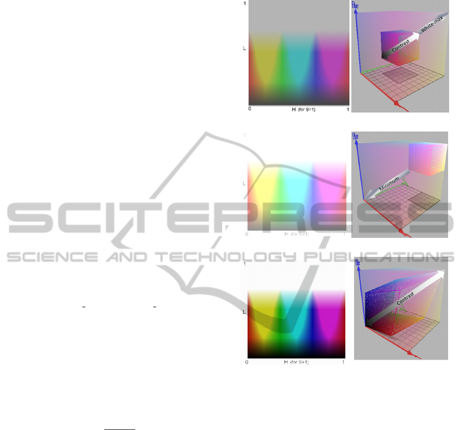
(a)
(b)
(c)
Figure 1: Color enhancement; (a) Low contrast image and
its RGB scatter plot of pixel colors; (b) image after global
white balance and its RGB scatter plot (c) enhanced image
using the proposed scheme and its RGB scatter plot.
4 CONTRAST ENHANCEMENT
ALGORITHM
Our proposed contrast enhancement algorithm uses
the amplitude limited vectors principledescribed
above, to improve contrast, and has no need for pa-
rameter adjustment.
The color enhancement algorithm has three
stages:
1. Global maximum luminance measure.
2. Linearly adding the difference between the maxi-
mum luminance and the measured one.
3. De-composing every pixel, using Eq. (14), with
the global minimum luminance.
RELATIVITY AND CONTRAST ENHANCEMENT
97

We choose to demonstrate these stages on a syn-
thetic example depicted in Fig 1. Let the test case
image be denoted by I, and its maximum luminance
value by I
max
(Fig. (a)). We first calculate the differ-
ence between I
max
and the maximum luminance pos-
sible, M:
D = M −I
max
. (20)
This vector is depicted in Fig. 1 at the top-right panel.
The second step, consist of adding D to all the pixels
in the original image I, i.e.
I
wb
= I + D (21)
This step is depicted in Fig. 1(b). All the operations
used in the first two stages are the usual addition and
subtraction of real vectors.
The last stage of our algorithm is based on
the connection between Weber’s law and KIP de-
composition proven in section 3.3. We denote the
current global minimum Luminance by min(I
wb
), this
value is depicted in the right panel of Fig. 1(b). Fi-
nally, Contrast enhancement is performed by KIP de-
composition as in Eq. (14):
BQ(I
contrast
) = I
wb
[−]min(I
wb
) (22)
= BQ(I
wb
) ·BQ(−min(I
wb
))
The final enhanced image is extracted from
BQ(I
contrast
) by using Eq. (12), and can be seen
in Fig. 1(c).
5 EXPERIMENTAL RESULTS
5.1 Contrast Enhancement
We demonstrate the validity of the enhancement al-
gorithm on several natural images with low contrast.
We compare our enhancement algorithm to the LIP
enhancement approach. The implementation of the
LIP approach follows the first two steps described in
Sec. 4, with the final step replaced by the LIP subtrac-
tion operation. Results can be seen in Fig. 2. Compar-
ing the images one can see that using the LIP frame-
work enhances also saturation of the color. This satu-
ration enhancement is a side effect not always needed.
KIP results can be made the same as LIP by using
a simple saturation enhancement. This enhancement
is linear and quick and can be seen in Fig. 2.
1. Calculate the image luminance using a known
method i.e. Luminance =
r
3
+
g
3
+
b
3
2. Calculate the image chrominance i.e.
Chrominance = Image −Luminance
3. Add together image luminance with image
chrominance multiplied by a scalar i.e. I
new
=
Luminance + 1.6 ·Chrominance
(a)
(b)
(c) (d)
Figure 2: Contrast enhancement using proposed scheme;
(a) Low contrast image; (b) contrast stretching using pro-
posed scheme in Logarithmic Image Processing (LIP); (c)
enhanced image using the proposed scheme in Caged Im-
age Processing (KIP); (d) Improving saturation of the KIP
enhanced image using a simple linear method.
5.2 Clipping Saturation Prevention
Although saturation enhancement can improve the
image - it is not always necessary and sometimes de-
grades the color image by the clipping of color and
loss of information.
We chose to compare KIP capabilities in prevent-
ing clipping of color caused by the LIP method. Be-
cause LIP treats every vector addition as a composi-
tion of its its individual elements, it can never distin-
guish between a vector which has a maximum value
in only one of its elements. For example, consider
v
1
= (0.99, 0, 0) with ||v
1
|| = 0.98, and a vector hav-
ing maximum value in more than one of its elements,
for example v
2
= (0.99, 0.99, 0) with ||v
2
|| = 1.4.
Clearly ||v
2
|| > ||v
1
|| but because LIP cannot distin-
guish between the two, a color clipping may occur.
An example of this can be seen by trying to en-
hance low contrast color patterns which are nearly
saturated. Because LIP treats each color channel on
its own (Patrascu and Buzuloiu, 2001), color clipping
occurs. This can be seen in Fig. 3 and Fig. 4.
6 CONCLUSIONS
In this paper we introduce a new mathematical model
to manipulate color images. This model is based on
IMAGAPP 2011 - International Conference on Imaging Theory and Applications
98
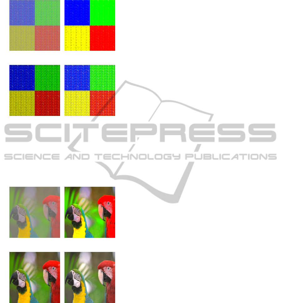
(a) (b)
(c) (d)
Figure 3: Contrast enhancement using proposed scheme
showing clipping of color under LIP framework; (a) Low
contrast image; (b) contrast stretching using proposed
scheme in Logarithmic Image Processing (LIP) showing
loss of information and clipping; (c) enhanced image using
the proposed scheme in Caged Image Processing (KIP);(d)
original image with full contrast
(a) (b)
(c) (d)
Figure 4: Contrast enhancement using proposed scheme
showing clipping of color under LIP framework; (a) Low
contrast image; (b) contrast stretching using proposed
scheme in Logarithmic Image Processing (LIP) showing
loss of information and clipping; (c) enhanced image us-
ing the proposed scheme in Caged Image Processing (KIP);
(d) original image with full sontrast
principles of special relativity for which the limited
amplitude vectors are most relevant to color image
processing. We show that the proposed model is con-
sistent with the LIP model and with the HVS. Using
this model we introduce a color enhancement algo-
rithm. We demonstrate its validity by several exam-
ples, and its advantage over existing methods.
REFERENCES
Coleman, B. (2006). Force and gravitation in special rela-
tivity. Il Nuovo cimento della societ
`
a italiana di fisica.
B, General physics, relativity, astronomy and mathe-
matical physics and methods, 121(6):579–586.
Coleman, B. and Kolaman, A. (2008). From amplitude-
limited vectors to Maxwell’s equations. Nuovo Ci-
mento B Serie, 123(1):1661–1670.
Debayle, J., Gavet, Y., and Pinoli, J. (2006). General
adaptive neighborhood image restoration, enhance-
ment and segmentation. Image Analysis and Recog-
nition, pages 29–40.
Deng, G. (2009). An entropy interpretation of the logarith-
mic image processing model with application to con-
trast enhancement. Image Processing, IEEE Transac-
tions on, 18(5):1135–1140.
Ell, T. and Sangwine, S. (2006). Hypercomplex Fourier
transforms of color images. Image Processing, IEEE
Transactions on, 16(1):22–35.
Ell, T. and Sangwine, S. (2008). Theory of vector filters
based on linear quaternion functions. EURASIP.
Hamilton, S. (1866). Elements of quaternions. Longmans,
Green, & co.
Ji, X., Wei, Z., and Feng, Y. (2006). Effective vehicle detec-
tion technique for traffic surveillance systems. Journal
of Visual Communication and Image Representation,
17(3):647–658.
Le Bihan, N. and Mars, J. (2004). Singular value de-
composition of quaternion matrices: a new tool for
vector-sensor signal processing. Signal processing,
84(7):1177–1199.
Moxey, C., Sangwine, S., and Ell, T. (2003). Hypercom-
plex correlation techniques for vector images. Signal
Processing, IEEE Transactions on, 51(7):1941–1953.
Patrascu, V. and Buzuloiu, V. (2001). A mathematical
model for logarithmic image processing. In Proceed-
ings of the 5th World Multi-Conference on Systemics,
Cybernetics and Informatics SCI, volume 13, pages
117–122.
Pinoli, J. (1997). The logarithmic image processing model:
Connections with human brightness perception and
contrast estimators. Journal of Mathematical Imag-
ing and Vision, 7(4):341–358.
Sangwine, S. (2002). Colour image edge detector based
on quaternion convolution. Electronics Letters,
34(10):969–971.
RELATIVITY AND CONTRAST ENHANCEMENT
99
