
A DYNAMIC TEACHING SYSTEM TO SUPPORT THE DESIGN
OF STRUCTURAL STEEL MEMBERS
Essam Zaneldin and Bilal El-Ariss
Department of Civil and Environmental Engineering, United Arab Emirates University, Al Ain, United Arab Emirates
Keywords: Visual Basic, Spreadsheets, Education, Structural Engineering.
Abstract: Advanced computer programs used for structural analysis and design have become widely used, however,
classical and easy-to-use tools, such as design charts and tables, are still preferable by students, who need
simple tools instead of sophisticated and time-consuming programs. These tools help students electronically
retrieve section properties-related information and use this information in the design of structural members.
It is, therefore, clear that design charts, tables, and section properties should be made electronically
available to engineering students. In this study, Microsoft Visual Basic, a widely-used and easy-to-use
programming language, was used to develop a system that provides students with the ability to create
powerful forms that can be used for different steel sections and their properties. The system was developed
to produce steel section properties provided in the AISC and CISC Manuals of Steel Construction and
needed in the design charts. This paper describes how the system was developed and presents some real-
world examples to illustrate its ease-of-use and powerful capabilities over current practices. Comments and
recommendations pertaining to future developments in the field are then presented in the conclusions.
1 INTRODUCTION
The complete design of any structure, including steel
structures, involves the design of the various
structural members as well as the connections
between the members. The integrity of the load path
depends on the strength of the different members
and attachments between members. The designer has
a choice of several steel sections several types of
connections; welded, bolted, riveted, or combination
of the above. Load calculations are quite complex
and lend themselves well to the use of a spreadsheet.
Spreadsheets have evolved into sophisticated
computation and presentation tools with a
tremendous potential for use as design tools. This
paper discusses the design of a steel plate girder and
how spreadsheets and Basic Visual programming
can facilitate the iterative design process by
incorporating the steel section properties needed.
The spreadsheet is designed for stand-alone use for
many common situations (Adeli and Wilcoski, 1993;
Wang et al., 2005; Yassin and Nethercot, 2007).
Spreadsheets have become increasingly popular
and widely used among structural engineers because
of the ease with which repetitive calculations can be
done for a series of variables (Zaneldin and Ashur,
2008; Zaneldin and El-Ariss, 2010). When a design
spreadsheet needs information for different steel
sections, the most efficient way to get this
information is to link the design spreadsheet to the
AISC Database. Microsoft Visual Basic (Microsoft
Visual Basic, 1998) offers users with the ability to
create database that can be used for different steel
sections and their properties. This database stores
the dimensions and properties for each steel section
listed in the Manual of Steel Construction.
Accessing this database allows users to
automatically lookup and input data that would
otherwise need to be manually referenced and
entered into a spreadsheet. This simple automation
process will allow a job to be done faster and will
lower the possibility for errors to occur, particularly
for students. Only a section’s designation needs to
be entered into a design spreadsheet, which can be
programmed to retrieve the necessary information
from the database. In this paper, an overview of
spreadsheets and its macros programming
capabilities was first presented and a dynamic
system was then developed using Visual Basic
programming language. The developed system can
be used to provide students with an easy access to
retrieve steel section properties that can be used for
349
Zaneldin E. and El-Ariss B..
A DYNAMIC TEACHING SYSTEM TO SUPPORT THE DESIGN OF STRUCTURAL STEEL MEMBERS.
DOI: 10.5220/0003378403490354
In Proceedings of the 3rd International Conference on Computer Supported Education (CSEDU-2011), pages 349-354
ISBN: 978-989-8425-49-2
Copyright
c
2011 SCITEPRESS (Science and Technology Publications, Lda.)
different structural steel members. The system was
developed to store and modify the different steel
section properties as provided in the AISC and CISC
Manuals of Steel Construction and needed in the
design charts. This paper describes the main
components of the system and presents a real-world
example to illustrate its ease-of-use and powerful
capabilities over current practices. Comments and
recommendations pertaining to future developments
in the field are then presented in the conclusions.
2 SPREADSHEETS
Spreadsheets are becoming increasingly popular.
Although spreadsheet programs developed by
various software firms have their own special
features, they are based on the same working
principles and, most of them, are compatible with
each other. The spreadsheets developed for the
graphic-based operating systems have commonly
and efficiently been used in recent years. A user can
move around among cells and write information on
them. The information may be numeric or
alphanumeric values or formulae. Values of
variables are written on the cells. The cells or the
group of cells can be named if required and
formulations can be expressed clearly with the help
of these names. All operations concerning
spreadsheets are conducted by a core program. This
program scans all the filled cells in the sheet and
searches for logical relations and updates the
operations at once when entering new information
into the cells. This feature is called automatic
interaction. One of the important concepts of
spreadsheets is that of range. A range covers one or
more rectangular cells of a sheet. The address of a
range can be defined by the addresses of both ends
of its diagonal. The addresses representing the
ranges can be used as parameters. Some
formulations can also be written on their defined
range. These types of formulations are used
particularly in matrix operations.
One of the most powerful tools of spreadsheets is
the use of Macros. Macros are small and powerful
code programs which can be written and executed in
spreadsheets. This is makes it convenient for
students as it provides them with the spreadsheet
environment while, at the same time, provides the
user with the powerful programming capabilities of
visual basic. Macros are defined in special sheets
called macro sheets. They use the cells of the sheets
as variables. There are two kinds: command macros
and function macros. Function macros assign the
values of special functions used in spreadsheets
while Command macros need special commands to
be executed.
3 THE DEVELOPED SYSTEM
When using a spreadsheet for the design of
structural steel members, and the design requires
information for different steel sections, the most
efficient way to get this information is to link the
design spreadsheet to the AISC or CISC Databases.
In this research, an easy-to-use system was
developed for the selection of different steel
members using Visual Basic. The different steel
section properties listed in the AISC and CISC
manuals of steel construction were stored in a
database that was developed using Microsoft Access
2007 (Microsoft Office Access, 2007). A VBA
macro was developed to allow students to easily
retrieve the databases by a click of a button in the
spreadsheet. This will also allow for automatic
lookup and input of steel section properties for use
in structural design that would otherwise need to be
manually referenced and entered into a steel design
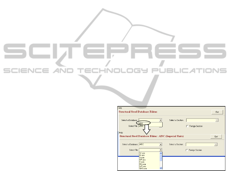
spreadsheet. A screen capture of the developed
system main screen is shown in Figure 1.
Figure 1: The developed system main screen.
As shown in Figure 1, when a database is selected,
all the available shapes will appear in the bottom left
part of the screen. When a shape is selected, the
different sections related to this shape will be listed
and the user can select a shape section. Once a shape
section is selected, all its properties will appear in
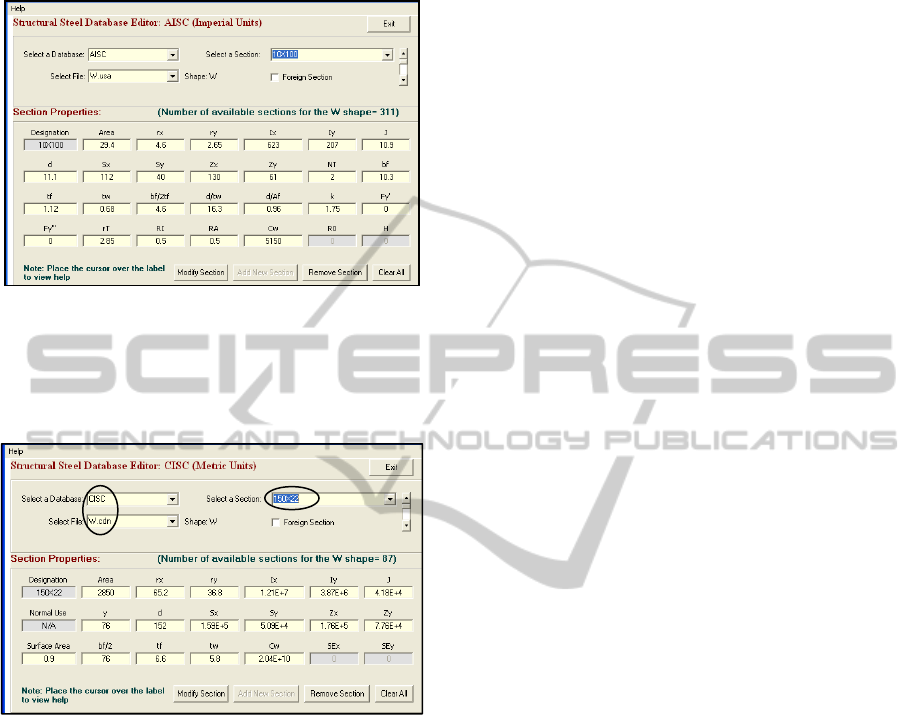
the bottom part of the screen as shown in Figure 2.
As shown in the figure, users can modify sections,
remove sections, or add new sections. Only a section
designation needs to be entered into a design
spreadsheet, which is programmed to retrieve the
CSEDU 2011 - 3rd International Conference on Computer Supported Education
350
necessary information from the database generated
by the developed system.
Figure 2: Properties of W10X100 AISC section.
Similarly, a user can also select a shape and section
using the CISC and the corresponding section
properties will appear as shown in Figure 3.
Figure 3: Properties of W150X22 CISC section.
4 APPLICATION EXAMPLE
In this example, the flexural yielding limit state is
used to analyze structural steel plate girders. The
flexural yielding limit state represents the absolute
maximum nominal moment that a section can
support. At this condition the section is fully
yielded. The limit state for strong axis bending in I-
shaped member is found in the 13
th
edition of the
AISC specifications of Steel Construction Manual
(SCM) F2.1 (AISC, 2005; ASCE, 2005) and for
weak axis bending in SCM F6. Other situations are
covered in other sections of SCM Chapter F and are
similar to those presented here. A brief background
about the limit state, lateral torsional buckling, and
cover plates was first given and a sample
spreadsheet calculation using the developed system
was then presented.
4.1 The Limit State
The basic limit state follows the standard form. The
statement of the limit states and the associated
reduction factor and factor of safety are given here:
LRFD ASD
M
u
< φbM
n
M
a
< M
n
/ Ω
b
Req'd M
n
= M
u
/φb < M
n
Req'd M
n
= M
u
Ω
b
< M
n
M
u
/(φb M
n
) < 1.00 M
a
/(M
n
/Ω
b
) < 1.00
φ
b
= 0.90 Ω
b
= 1.67
The values of M
u
and M
a
are the LRFD (Load
Resistance and Factor Design) and ASD (Allowable
Stress Design) factored loads, respectively, applied
to the flexural member. In this case M
n
is the
nominal flexural yielding strength of the member.
For doubly symmetric compact I-shaped members
and channels bent about their major axis:
M
nx
= M
px
= F
y
Z
x
for strong axis bending (AISC
2005 equation F2-1)
M
ny
= M
py
= min (F
y
Z
y
, 1.6F
y
S
y
) for weak axis
bending (AISC 2005 equation F6-1)
Where: M
p
is the plastic flexural strength of the
member; F
y
is the material yield stress; and Z is the
plastic section modulus for the axis of bending being
considered.
4.2 Lateral Torsional Buckling
Lateral torsional buckling (LTB) is a strong axis
phenomenon. It needs not be considered for weak
axis bending. The equations for each of the cases
shown in SCM Table User Note F1.1 are found in
Chapter F sections referenced in the table. The
general form used to compute LTB effects is the
same for cases F2, F3, F4, and F5. The differences
are in the computation of the key quantities and the
details of the equations used in various buckling
ranges. Note also that web slenderness is considered
in several of the LTB cases. As a result, Web Local
Buckling (WLB) is integrated in the LTB equations,
making WLB only a consideration for HSS and
other square and rectangular tubes.
4.3 Cover Plates
Cover plates are plates added to the flanges of beams
A DYNAMIC TEACHING SYSTEM TO SUPPORT THE DESIGN OF STRUCTURAL STEEL MEMBERS
351
to increase the flexural capacity of the beam over
some portion of the beam. The use of cover plates in
regions of high moment allows the use of a section
of lesser weight and lesser flexural capacity to be
used as the primary beam. This may result in a cost
savings in some cases. This technique is useful for
compact beams that are not subject to the limit state
of LTB. SCM F13.3 specifies many of the
parameters associated with the design of cover
plates.
In the case of a compact beam not subject to
LTB, the flexural limit state is stated as:
Req'd M
n
= (M
u
/φ or M
a
Ω) < F
y
Z
total
Adding cover plates increases the Z of the
section. For symmetrical cross sections with
symmetrically applied plates, the design inequality
becomes: Req'd M
n
< F
y
(Z
section
+ Z
plates
)
For design purposes, this equation can be re-
written as: Z
plates
> (Req'd M
n
/F
y
) – Z
section
For symmetrical plates, Z is the area of one plate
times the distance between the centers of the two
plates, so the strength requirement for symmetrical
cover plates becomes:
Z
plates
= bt (d+t) > (Req'd M
n
/F
y
) – Z
section
Where: d is the overall depth of the steel section to
which the cover plates are being added; and t is the
thickness of the cover plates.
For unsymmetrical plates (i.e. the cover plates
are of different sizes or a cover plate is applied to
only one flange), the Z for the whole section must be
recomputed using basic concepts. This will involve
finding the centroidal axis, locating
the center of the
areas above and below the centroidal axis, then
finding Z by:
Z
total
= (A
g
/2) (distance between the centroids of the
two halves)
A restriction on the relative values of b and t is
the requirement that the plate be compact. As the
plate is generally connected to the flange with welds
or bolts on both sides, the cover plated is considered
a stiffened element and SCM Table B4.1 case 12
applies: b/t < 1.12 sqrt(E/F
y
)
As there are two design variables, b and t, there
are an infinite number of combinations of the
variables that will result in a Z
total
that matches Z
req'd
.
The best solution is generally the one that yields the
smallest area. The end result of the analysis process
is that the internal moment is larger than the moment
predicted by normally used first order (i.e.
equilibrium on the un-deflected shape) analysis. It is
important that the increased moment (sometimes
referred to as a "magnified" moment) be used when
comparing required strength to actual strength.
Failure to do so is non-conservative.
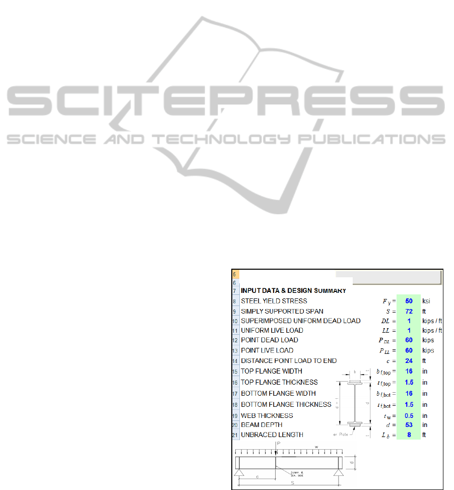
4.4 Sample Spreadsheet Calculations
Because the calculations above must be performed,
the analysis can be done efficiently with a
spreadsheet. The spreadsheet example shown in
Figures 4 and 5 show some of the analysis steps for
a steel plate girder. The database generated using
Visual Basic stores the dimensions and properties
for each steel section listed in the Manual of Steel
Construction. Accessing this database using macros
executed from within spreadsheets, allows for
automatic lookup and input of data that would
otherwise need to be manually referenced and
entered into the spreadsheet. This simple automation
process will help students in easily enter
corresponding section properties and allow a job to
be done much faster with fewer errors.
As shown in Figures 4 and 5, the spreadsheet was
used to calculate the width to thickness ratios for
both the web and flange of the structural steel
section. The allowable flexural strength was then
calculated based on AISC 360-05 Chapter F4. For
these calculations to take place several section
properties need to be input to the spreadsheet. The
system was used to automatically input these
properties as soon as the structural steel shape and
section is selected. This makes it easy for students to
automatically input the section properties instead of
doing this manually. Students will use the
spreadsheets to perform the necessary calculations
and the already-developed VBA macro shown in
Figures 4 and 5 can then be used to retrieve any
Figure 4: Plate girder input data.
Plate Girder Design
Based on AISC 360-05
Retrieve Section Properties
Cover Plate
CSEDU 2011 - 3rd International Conference on Computer Supported Education
352
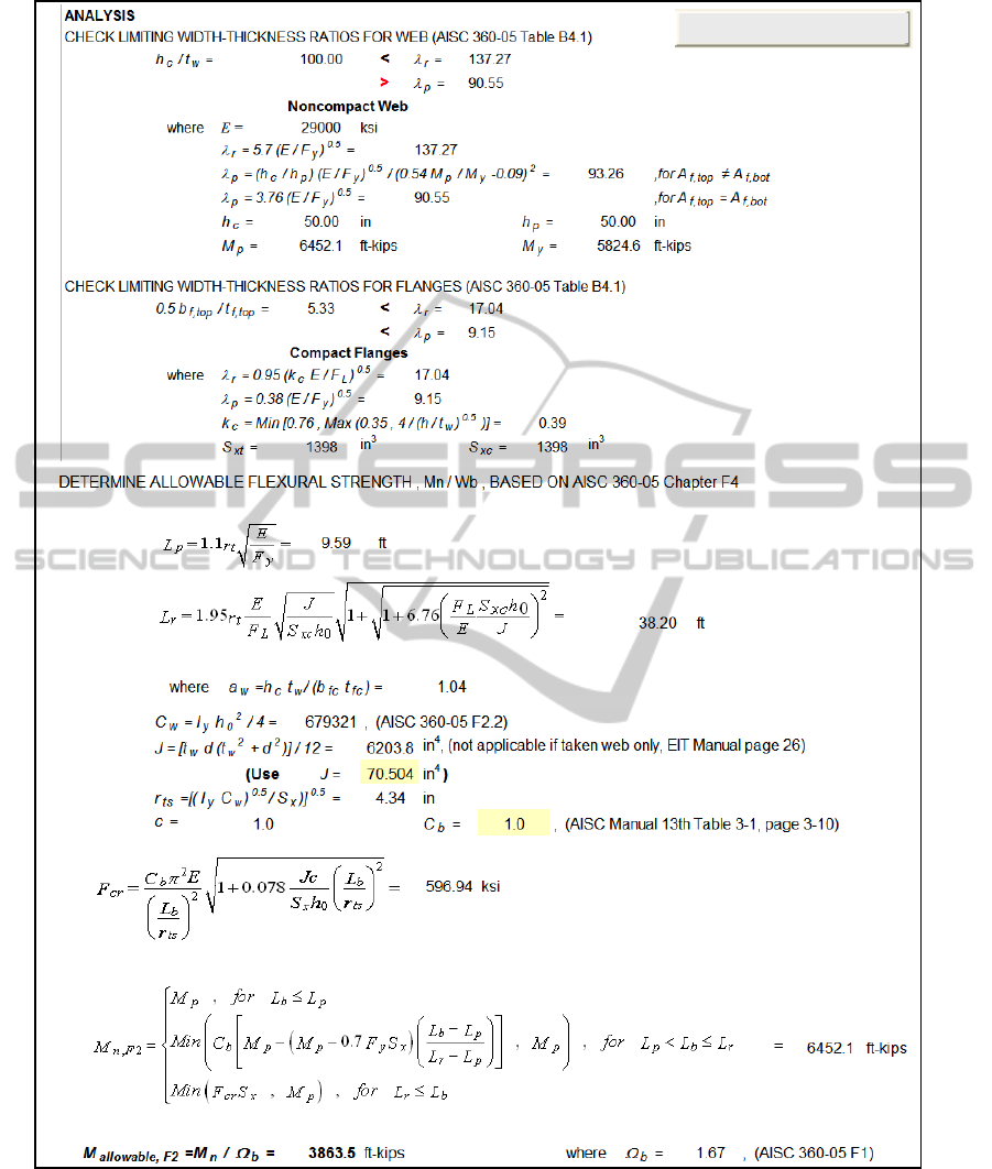
Figure 5: Plate girder analytical results.
required AISC or CISC section properties. It also
avoids errors and mistakes resulting from inputting
the wrong section properties.
5 CONCLUSIONS
In this paper, dynamic system was developed using
Visual Basic programming language. The developed
Retrieve Section Properties
A DYNAMIC TEACHING SYSTEM TO SUPPORT THE DESIGN OF STRUCTURAL STEEL MEMBERS
353

system can be used to provide students with an easy
access to retrieve section properties that can be used
for different structural steel members. The system
was developed to store and modify the different steel
section properties as provided in the AISC and CISC
Manuals of Steel Construction and needed in the
design charts. This paper described the main
components of the system and presents a real-world
example to illustrate its ease-of-use and powerful
capabilities over current practices. The developed
dynamic system can also be used by professional
engineers during the structural design of steel
buildings as an automated tool to replace the manual
use of steel charts and manuals. Once a design
spreadsheet is programmed, a user only needs to
input a section designation and the spreadsheet will
determine the other desired information. This can be
done quickly and accurately for a series of steel
sections making spreadsheets a very powerful design
tool.
Authors are currently working in automating the
structural design process and linking it with required
design codes, standards, charts, and manuals. The
developments made in this regard will be presented
in a separate paper.
REFERENCES
Adeli, H., Wilcoski, J., 1993. A methodology for the
evaluation of structural design software. Computers &
Structures, Volume 49, Issue 5, pp. 877-883.
AISC Manual of Steel Construction, 13
th
Edition, 2005.
American Institute of Steel Construction, Chicago.
ASCE 7-05, 2005. Minimum design loads for buildings
and other structures. American Society of Civil
Engineers, Reston, VA.
Microsoft Office Access 2007. Microsoft Corporation,
One Microsoft Way, Redmond, Washington, USA.
Microsoft Visual Basic 6.0, 1998. Microsoft Corporation,
One Microsoft Way, Redmond, Washington, USA.
Wang, Z-H, Au, S. K., Tan, K. H., 2005. Heat transfer
analysis using a Green’s function approach for
uniformly insulated steel members subjected to fire.
Engineering Structures, Volume 27, Issue 10, pp.
1551-1562.
Yassin, A. M., Nethercot, D. A., 2007. Cross-sectional
properties of complex composite beams. Engineering
Structures, Volume 29, Issue 2, pp. 195-212.
Zaneldin, E. and Ashur, S., 2008. Using spreadsheets as a
tool in teaching construction management concepts
and applications. The 2008 American Society of
Engineering Education (ASEE) Annual Conference,
June 22-25, Pittsburgh, PA, USA.
Zaneldin, E. and El-Ariss, B., 2010. Using spreadsheets
and VBA for teaching civil engineering concepts. The
International Conference on Education, Training and
Informatics (ICETI 2010), April 06-09, Orlando, USA.
CSEDU 2011 - 3rd International Conference on Computer Supported Education
354
