
AUTOMATIC MESH SEGMENTATION USING ATLAS
PROJECTION
AND
THIN PLATE
SPLINE
Application for a Segmentation of Skull Ossicles
Makram Mestiri, Sami Bourouis and Kamel
H
a
mroun
i
National Engineering School of Tunis, University of Tunis, El
Manar,
Tunis, Tunisia
Keywords: Mesh, 3D segmentation, Registration, Thin-plate spline, Atlas, Skull
bones.
Abstract: Mesh segmentation has become a crucial step in many computer graphics applications. This paper
provides new method for three dimension Atlas based mesh segmentation using thin plate spline approach
(TPS) and a new FNN algorithm. This method consists of three steps: first, we apply a rigid registration
between two meshes the atlas and the mesh to segment. The second step is the application of an elastic
registration using thin plate spline method. The last step is the identification of the different regions to
segment the mesh using our FNN algorithm. We tested the performance of our method on synthetic images
and on a real human skull and found that the preliminary results obtained are satisfactory.
1 INTRODUCTION
In medical imaging, the use of three- dimension
shape has greatly facilitated the disease diagnosis.
Segmentation is an important and difficult step in
medical images analysis. The segmentation of
polygonal meshes can divide the mesh into multiple
segments in order to simplify or change the mesh
representation to another representation more
meaningful and easier to analyze.
There was a wealth of research focused on
methods for polygonal meshes segmentation we can
classify them into two categories: methods based on
geometric features, and methods based on semantic
approaches.
In the first case, the shape is segmented into a
number of uniform patches with respect to some
surface properties, while in the second one the
segmentation is aimed at identifying relevant
features of the shape. In patch segmentation
methods, shapes are divided into regions that have
certain geometric features such as flatness,
convexity, approximation to a primitive bend
(Shamir, 2008).
Among the most frequently used algorithms, we
cite the growth of regions, watershed, deformable
models, hierarchical partitioning, spectral
partitioning and skeletonization.
Segmentation into meaningful parts: This type of
segmentation can divide the object into meaningful
components. This segmentation is mainly based on
human perception. Thus, some researchers propose
to use primitive specifying the 3D shape such as
boundaries to break down a scene or object (Lon,
2007).Others use models (Atlas) to project the
predefine segmentation of the atlas to the object to
be segmented (Commowick, 2010). The atlas based
segmentation has become a standard method for
brain segmentation Oliver (Oliver, 1998) summar-
izes the segmentation of the brain atlas in three
stages. The first step is to match the image overall
patient and image atlas for which they are located in
the same repository. The second step is to apply a
local deformation to bring the two images perfectly.
Finally a transformation will be applied to the
atlas image.
An illustration showing figure1 the difference
between the two method (surface patches and
significant parts).
a b
Figure 1: (a) Segmentation using patch approaches
(Shamir, 2008), (b) Segmentation into meaningful parts
(Katz, 2006).
221
Mestiri M., Bourouis S. and Hamrouni K..
AUTOMATIC MESH SEGMENTATION USING ATLAS PROJECTION AND THIN PLATE SPLINE - Application for a Segmentation of Skull Ossicles.
DOI: 10.5220/0003371702210225
In Proceedings of the International Conference on Computer Vision Theory and Applications (VISAPP-2011), pages 221-225
ISBN: 978-989-8425-47-8
Copyright
c
2011 SCITEPRESS (Science and Technology Publications, Lda.)
The areas of use of mesh segmentation are
numerous. Among them, we cite: the texture
mapping (Delest, 2008), the mesh parameterzation
remeshing, mesh simplification, meta morphosis
(Delest, 2007), mesh compression (Karni, 2000),
collision detection, pattern Recognition and reverse
engineering.
In this work, we propose a automatic
segmentation method based on atlas projection and
thin plate mesh deformation. Details of the method
will be discussed later. We also present some
experimental results obtained on synthetic meshes
and other real skull shapes.
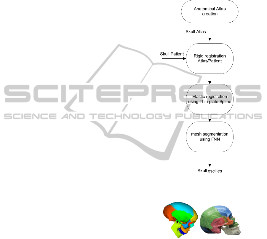
2 PROPOSED METHOD
We propose a segmentation method in the relevant
parts of triangular meshes by atlas projection. The
main purpose of this method is to identify the
various bones of the human skull. The method
consists of three stages: The first step is to apply a
rigid registration between two shapes as input, the
thin plate algorithm is then applied to minimize the
distortion between the atlas shape and the patient
one. During the third step, we apply our “FNN”
(finding nearest neighbors) algorithm to classify all
the bones composing the skull.
Since there is no literature in about pre-
segmented human skull, we had to manually
segment atlas shape to make it as anatomical atlas.
Figure 2 illustrates the different stages of the
proposed method.
2.1 Creating an Anatomical Atlas
To create an atlas for the human skull, we manually
segmented a reference mesh in nine different regions
representing nine bones using real skull atlas. We
have developed a tool to manually segment a shape.
Once we have identified a set of nodes that represent
a logically related region we labeled the different
region with different colors figure 3.
This tool provides high accuracy in the
classification stage of the various vertex of the mesh.
2.2 Rigid Registration
Mesh registration is a technique used to find a
transformation for mapping a source mesh known as
a reference mesh and a target mesh. Note here that a
change of scale is required if the difference between
the size of two meshes is important. This step is
performed before applying the registration between
two images. In this study, we targeted the rigid
registration between two different meshes using the
ICP algorithm (Iterative Closest Point) (Zheng,
1992).
Figure 2: Proposed Method.
Figure 3: (a) Reference 2d images, (b) 3d
anatomical
mesh.
Each region will contain points belonging to the
same skull ossicle.
The principle of ICP is to iterate between a step
of mapping data and another step of optimization of
rigid transformation until convergence.At each
iteration,the Algorithm provides a list of matched
points and an estimate of the transformation, the
algorithm converges when the error in distance
between matched points is below a certain threshold.
The transformation used for registration is composed
of a rotation and a 3D translation.
a
b
VISAPP 2011 - International Conference on Computer Vision Theory and Applications
222

Algorithm 1.
1. for each region OSi representing a skull
2. Repeat
3. Manual selection of a point compatible
with
e
OSi
.
4. Issuance of the color Ci in point e in
the
image
5. Choosing a Surrounding
number of
neighbors
at this
point that belongs to the same
ossicle
6. Retrieving neighbors IDs in
a
list
L
7. While L
≠
Ø
Remove the next element
s
of L
Save the coordinates
of
s Provide color Ci at
the
point
s
8. If the neighbors are not all compatible
with
OSi then
back
into
9. Until browned all points of
OSi
We chose to represent 3D rotation by the
technique of quaternion as it offers much more
flexibility algorithmic and numerical stability.
If we represent the quaternion by a vector: q
R
=
[q
0
, q
1
, q
2
, q
3
]
t
, such that q
02
+ q
12
+q
22
+ q
32
= 1, then
the rotation matrix R (q
R
) can be written as a
linear combination of these terms. If moreover, we
denote by q
T
translation vector as q
T
= (q
4
, q
5
, q
6
),
then the rigid transformation used by the ICP
algorithm is as follows:
[]
),,,,,(q|
65,43210T
qqqqqqqqq
R
==
(1)
If we denote by CP
1
and CP
2
two sets of
points to be matched by ICP, then we have:
)()(*)(
21
iCPqiCPqR
TR
≈+
(2)
The registration problem amounts to minimizing
the following quadratic error:
2
12
1
1
( ) () ( ( )* () )
Np
kkkk
RT
i
p
err q CP i R q CP i q
N
=
=−+
∑
(9)
With Np is the number of points CP
1
and CP
2
and k
is the index of current iteration. Thus the ICP
algorithm can be formulated as follows (Delest,
2008).
Algorithm 2.
1.Begin
2.Initialize k = 1, T
k
= T
i
,
convergence = 0
3.While (k <kmax or
convergence
==
0)
-Compute for each point of the set of D
’2
(D
'2
=
Tk.D
2
) the
nearest point across D
1
(or
vice versa). The resu lt
matched the list of issues [CP
1
, CP
2
].
-Calculate the transformation
T
with the use of
quaternion
whose input CP
1
, CP
2
and T
k
and
minimizing
the
error:
21
1
*() ()
k
TCPi CPi
N
ε
=−
(4)
N is the number of points CP
1
and
CP
2
.
- Update T
k
= T, k =
k
+1
- If convergence condition
satisfied
=>convergence =
1
End
While
End
2.3 Elastic Registration using
Thin-plate Spline
Mesh elastic registration is a mesh deformation
process; one of the transform -ations that are able to
represent elastic deformations is the thin-plate spline
(TPS). Thins plate spline were introduced by
Bookstein, in (Bookstein,1989) for geometric
design. In two dimension images the TPS model
describes the transformed coordinates (x
T
,y
T
) both
independently as a function of the original
coordinates (x, y):
(x
T
,y
T
)=(f
x
(x,y),f
y
(x,y))
(5)
Algorithm begin with given a displacements of a
number of landmark points, the TPS model
interpolates those points, while maintaining maximal
smoothness. For each landmark point (x,y), the
displacement is represented by an additional z-
coordinate, and, for each point, the thin plate is fixed
at position (x, y, z). The strain energy is calculated
by integrating the second derivative over the entire
surface that can be minimized by solving a set of
linear equations.
dxdy
y
z
yx
z
x
z
R
∫∫
⎟
⎟
⎠
⎞
⎜
⎜
⎝
⎛
⎟
⎟
⎠
⎞
⎜
⎜
⎝
⎛
∂
∂
+
⎟
⎟
⎠
⎞
⎜
⎜
⎝
⎛
∂∂
∂
+
⎟
⎟
⎠
⎞
⎜
⎜
⎝
⎛
∂
∂
2
2
2
2
2
2
2
2
2
.2
(6)
The TPS model for one of the transformed
coordinates is given by parameter vectors a and D:
F(
x
T
,y
T
)=a
1
+
a
2
x+a
3
y+…+
()
()
∑
=
−
n
i
ii
yxLFD
1
,
(7)
Where F(r)= r
2
log(r) is the basis function, a =
[a
1
a
2
a
3
a
4
]
T
defines the affine part of the
transformation, D gives an additional non-linear
deformation, and the L
i
are the landmarks that the
TPS interpolates figure 4.
Figure 4: Thin plate
spline
interpolation of 15
points.
AUTOMATIC MESH SEGMENTATION USING ATLAS PROJECTION AND THIN PLATE SPLINE - Application for
a Segmentation of Skull Ossicles
223

Algorithm 3.
1. Given a set of source landmark we define
P
matrix of (3xn) n
number of
vertex
⎥
⎥
⎥
⎦
⎤
⎢
⎢
⎢
⎣
⎡
=
...
1
1
22
11
yy
xx
P
2. Using the basis function we define matrix
K
(n x
n)
⎥
⎥
⎥
⎥
⎦
⎤
⎢
⎢
⎢
⎢
⎣
⎡
=
0...)()(
...0......
)(...0)(
)(...)(0
1212
1212
1212
rFrF
rFrF
rFrF
K
3. Define M combination of K and
P
matrix
⎥
⎦
⎤
⎢
⎣
⎡
=
OP
PK
M
T
Where O is a 3x3 matrix
of
zeros
4. Inverse M matrix on to another Z matrix defined as
M
−1
Y= (D|a
1
a
2
a
3
)
T
5. Define a function F(x
T
,y
T
)= a
1
+ a
2
x+a
3
y+…+
(
)
(
)
∑
=
−
n
i
ii
yxLFD
1
,
Every were in
the
plane
(Rohr, 1999) proposed a method to estimate thin
plate splines. The method interpolates some of the
points using smoother transfor-mation controlled by
a parameter µ, which weights the optimization of
landmark distance and smoothness. For µ = 0, there
is full interpolation, while for very large µ, there is
only an affine transformation left. In our methods
the landmarks used in the TPs algorithm are the
entire atlas mesh vertex.
2.4 Mesh Segmentation
At this level, we must label the resulting mesh vertex
from the previous step using the atlas mesh.
Clustering of vertex in specific classes is done
according to the following algorithm
Algorithm 4.
1.
R
epeat
2. For P1 a vertex of the patient
skull
Make
- Identify the point P2 in the mesh of the
atlas
that is as
close as possible to the point P1
through
the
Calculation of
a
Euclidean distance.
-Identify RAi region is located in the
P
2,
which corresponds
to an ossicle
i
-Classify P1 in the region that corresponds
to
the
RPi
ossicle
i
EndFor
Until term of the entire
patient
mesh
vertex
.
The “FNN” algorithm starts with the creation of
regions representing the various bones of the skull.
Then, it identifies the entire vertex that exists in the
mesh to segment. For each point, it searches the
closest point in the mesh atlas. Finally, as a result all
vertex of the classified mesh is segmented into
regions, each one of them represent ossicles of the
skull.
3 EXPERIMENTAL RESULTS
Validation is a fundamental step to enhance the
robustness and effectiveness of our method. For this
reason, we begin by validating our method on
synthetic meshes before doing it on real human
skull. We have also proposed a validation tool,
providing additional flexibility to the user deal with
the selection of algorithm parameters.
Subsequently, we present preliminary results of
this work.
3.1 Automatic Segmentation of Simple
Shapes
The objective of this validation is to study the
performance of our algorithm on simple shapes with
limited number of vertex. A sample result is given in
Figure 5 illustrating the various steps of our method.
Indeed, we have manually created a synthetic 3D
model as the anatomical atlas, as shown in Figure
5(b).
The result of application of rigid registration
between the mesh Figure 5(b) and the model is given
in Figure 5(c).
Finally, accurate identification of each
homogeneous region, which is based on “FNN” and
elastic registration, is shown in Figure 5(d).
Figure 5: (a) Synthetic model to be
segmented,
(b)
Rigid
registration, (c) Synthetic
model
segmentation without
elastic registration,
(d)
Synthetic model segmentation
after
elastic
registration.
These results are very satisfactory, which proves
the effectiveness of the method. Nevertheless, it is
important to check the robustness of the algorithm
on real images.
c
a
b
d
VISAPP 2011 - International Conference on Computer Vision Theory and Applications
224

3.2 Segmentation of Skull Bones
We are interested in the detection of various human
skull bones. Figures 5(c) and 6 show the results of
applying our method on the mesh of a patient who is
shown in Figure 5(b). Thus, the mesh is segmented
into nine areas that represent the different bones.
Following this experience, we noted the
existence of a limited number of mesh points that
were not labeled at the frontal bones and mandible,
while the other bones have been correctly detected.
We can therefore estimate that qualitatively the
results are satisfactory.
Figure 6: (A) Human skull atlas, (b) patient
skull,
(c)
segmentation result of the patient
skull before rigid
registration, (d)
Final segmentation result of the patient
skull.
Figure 7: Result of the segmentation of
the
skull in 6
ossicles.
4 CONCLUSIONS
Mesh segmentation are one of the major problems in
3d image analysis. In this context, we proposed a
solution to divide a given shape into meaningful
parts using atlas projection. It uses a rigid
registration and the elastic registration with TPS to
minimize distortion and uses a proposed “FNN”
algorithm to identify the final mesh parts. The
results are qualitatively very interesting
REFERENCES
Shamir, S. A survey on mesh
segmentation
techniques.
Computer Graphics, 27(6) (2008),
p.
1539-1556.
Bourouis, S., Hamrouni, K.
Multiresolution
mesh
segmentation of mri brain
using
classification and
discrete.Visapp, volume
1
(2008), p.
421-426.
Lon-Page, D. Part decomposition of 3d surfaces
.
Theses (2007).
Commowick, O. Outils de
contourage,
utilisation et
construction
d'atlas
anatomiques:
exemples des
cancers de
la
tête et du cou. Cancer Radiotherapie
(2010), p.
206-212
Delest, S. La segmentation de maillages 3D
en
patchs
surfaciques: applications
et
méthodes. Revue
Electronique
Francophone
d'Informatique Graphique,
Vol. 2, Num.
1
(2008)
Delest, S., Bone, R., Cardot, H.: Etat de
l'art
de la
segmentation de maillage 3d
par
patchs
surfaciques. GTMG,
Valenciennes,
France
(2007).
Delest, S., Bone, R., Cardot, H.
La
segmentation de
maillages polygonaux
en
carreaux surfaciques:
application
et
méthodes. Revue
Electronique
Francophone d'Informatique Graphique
2(1),
(2008),
p.
11-31.
Karni, Z., Gotsman, C. Spectral compression
of
mesh
geometry. Proceedings of the 27th
annual
conference
on Computer graphics
and
interactive techniques
(2000), p.
279-286.
Dominique, B. Méthodologies en
Imagerie
Médicale,
Book, LIP6 – UPMC,
(2008).
S. Katz, M. Mortara, and G. Patan´e Mesh Segmentation
- A Comparative Study SMI '06 Proceedings of the
IEEE International Conference on Shape Modeling
and Applications 2006
Hao Zhang Oliver van Kaick Ramsay
Dyer
Spectral
Mesh Processing
Graphic
s,
Usability
and
Visualization (GrUVi)
Lab,
School of Computing
Science, Simon Fraser University,
Canada
Zheng you Zhang Iterative point matching
for
registration of free-form curves.Book,
1992
Bookstein Fred L. Principal Warps:
Thin-plate
Spline
and decomposition of
deformations
.Transictions on
pattern analysis and
machine
intelligence. Vol 11;
NO
16/
june
1989
K. Rohr, M. Fornefett, and H.S.
Stiehl,
.Approximating
thinplate splines for
elastic
registration: Integration
of landmark
errors
and
orientation attributes. In
Proc.
16th Int. Conf. Information Processing
in
Medical
Imaging, Hungary, June 1999,
LNCS
1613,
pp. 252.265.
Asker M. Bazen and Sabih H. Gerez
Elastic
Minutiae
Matching by Means of
Thin-Plate
Spline Models
University of
Twente,
Department of Electrical
Engineering
P.O.
box 217, 7500 AE
Enschede.
Olivier Coulon, Jean Francois Mangin and Vincent
Frouin Robust Brain Segmentation Using Histogram
Scale-Space Analysis and Mathematical Morphology
MICCAI '98 Proceedings of the First International
Conference on Medical Image Computing and
Computer-Assisted Intervention
a
b
c
d
AUTOMATIC MESH SEGMENTATION USING ATLAS PROJECTION AND THIN PLATE SPLINE - Application for
a Segmentation of Skull Ossicles
225
