
AN EFFICIENT ROUTER ARCHITECTURE FOR NETWORK
ON CHIP
A. Shahrabi and A. Ahmadinia
School of Engineering and Computing, Glasgow Caledonian University, Glasgow, U.K.
Keywords: Network-on-Chip, Router Architecture, Low Power Design, Performance Evaluation.
Abstract: Efficient buffer management is not only instrumental in the overall performance of the on-chip networks but
also greatly affects the network energy consumption. In fact, any improvement or deterioration of network
performance and energy budget is the net result of increasing buffer utilisation (storing blocked flits) and
reducing buffer utilisation (delivering buffered flits). In order to improve the network performance and
efficiently utilising the available routers buffer space in NoCs, a new router architecture, called Pool-
Buffering (PB), is proposed in this paper. By exploiting a flexible ring buffer structure, the buffer space of
the proposed architecture is shared amongst all input channels; allocating more buffer to the busy input
channels and less to the idle ones. Implementation results show up to 50% in reducing power consumption
when compared to a traditional router. Moreover, our extensive simulation study shows that the proposed
router architecture enhances the network performance by increasing the acceptance traffic rate and
decreasing the average message latency.
1 INTRODUCTION
Network on Chip (NoC) is an emerging
communication-centric architecture for future
complex System-on-chip (SoC) design providing
scalable, energy efficient and reliable
communication. In a NoC system, different
components such as computation elements,
memories and specialized IP blocks exchange data
using a network as a communication infrastructure.
Designing a flexible on-chip communication
network for a NoC platform, which can provide the
desired bandwidth 0 and can be reused across many
applications, is a challenging task as a trade-off has
to be made between a number of cross-cutting
concerns such as performance, cost and size. In
addition to the technology in which the hardware is
implemented, topology, switching method, routing
algorithm and the traffic pattern are some other key
factors which have direct impact on the performance
of a NoC platform.
To meet these challenges, research carried out in
the field has proposed the idea of using a packet
switched communication network for on-chip
communication. A packet switched NoC consists of
an interconnection of many routers that connect IPs
together to form a given topology in order to enable
a large number of units (cores) to communicate with
each other.
Current routers reduce message latency by using
wormhole switching. In wormhole switching, a
message is divided into elementary units called flits,
each composed of a few bytes for transmission and
flow control. The header flit governs the route and
the remaining data flits follow it in a pipelined
fashion. When the header is blocked, the data flits
are blocked in situ. Throughput in wormhole-
switched networks can be increased by efficiently
allocating routers buffer. This also greatly affects the
network energy consumption and area occupied by
an on-chip router as the router buffers have the
largest leakage power consumption 0 and major
occupied area 0, 0, 0. In fact, any improvement or
deterioration of network performance and energy
budget is the net result of increasing buffer
utilisation (storing blocked flits) and reducing buffer
utilisation (delivering flits).
In order to improve the network performance and
efficiently utilising the available routers buffer space
in NoCs, a new router architecture is proposed in
this paper. By exploiting a flexible ring buffer
structure, the buffer space of the proposed
architecture is shared amongst all input channels;
405
Shahrabi A. and Ahmadinia A. (2011).
AN EFFICIENT ROUTER ARCHITECTURE FOR NETWORK ON CHIP.
In Proceedings of the 1st International Conference on Pervasive and Embedded Computing and Communication Systems, pages 405-412
DOI: 10.5220/0003371604050412
Copyright
c
SciTePress

allocating more buffer to the busy input channels and
less to the idle ones.
The rest of the paper is organised as follows.
Section 2 briefly surveys the previous works done in
the field of router architecture for NoC. Section 3
presents NoC structure, traditional router design
which is followed by the architecture of the proposed
NoC router. Section 4 presents a hardware cost
analysis. The performance study is presented in
Section 5. Finally, Section 6 concludes the study.
2 RELATED WORK
NoC has been under the spotlight since it was first
introduced and many research groups are working on
different aspects of NoC design, such as network
topologies, routing strategies and router
architectures.
A packet-switched architecture with switches
surrounded by six resources and connected to 6
neighbouring switches is proposed (Hemani et al.,
2000). The architecture was called honeycomb due
to the hexagon based pattern of switches and
resources. The concept of packet switching re-
appeared in other consecutive approaches but the
topology simplified in most proposals to a mesh of
resources and switches (Guerrier and Greiner, 2000).
Benini and Micheli (Benini and Micheli, 2002)
proposed a layered design methodology borrowing
models, techniques and tools from the network
design field and applying them to SoC design.
Most of these architectures were designed as
fixed and static structure, which lacks flexibility for
the communication of cores in a run-time
reconfigurable system which needs an adaptive
network. To tackle this problem, Bobda et al.
(Bobda et al., 2005), (Bobda and Ahmadinia, 2005)
presented DyNoC architecture as a communication
infrastructure for modules which are dynamically
placed on a run-time reconfigurable device. The
dynamically placed modules in DyNoC deactivate
the routers which are at their placement region.
Although network topology has a significant
impact on NoC performance and efficiency, routers
as the basic building blocks of NoC play a key role
in efficiency of resource utilisation as well as delay
and throughput of data transfers. Bahn et. al (Bahn et
al., 2007) designed a robust router in SystemC which
is scalable and deadlock and livelock free. They
focus on the protocol of packet processing, rather
than its hardware architecture and buffer
management. A heterogeneous router is proposed in
(Kreutz et al., 2005), which can interface
interconnection links with different bandwidths. This
has been achieved by using wrappers which is not
ideal. To speed up data transfer, Lee and
Bagherzadeh (Lee and Bagherzadeh, 2006) used
different clocks for head and body flits. Body flits
can be forwarded immediately and faster than head
flit since the routing path has been already
established. Ahmad et. al (Ahmad et al., 2008)
designed a bus based interface as a wrapper for
heterogeneous NoCs to facilitate cores integration
within the NoC.
In the area of buffer management, an optimisation
algorithm is proposed to predetermine buffer sizes
based on analysis of application specific traffic
patterns (Jingcao and Marculescu, 2004). In recent
years, there have been few studies on dynamic buffer
management based on traffic patterns. In (Faruque et
al., 2008), an adaptive architecture with runtime
observability is presented. The architecture changes
packet routing and buffer sizes when a fault occurs
i.e. packet loss. This architecture does not consider
traffic patterns to avoid any packet loss. In (Matos et
al., 2009), the router changes buffer depths at run-
time according to the system needs. The buffer depth
is obtained from a borrowing/lending process among
the adjacent channels. Therefore, an input channel
can reuse its neighbour channel buffers and increase
its depth up to three times.
The main contribution of this paper is design of a
router with ring buffer architecture to maximise
buffer utilisation when there is a heavy traffic rate on
a specific channel which can increase its depth up to
five times in a mesh topology or even more in other
topologies such as hexagonal networks. In other
word, the buffer depth for a channel can be stretched
up to number of dedicated buffer channels in the
router.
3 NETWORK-ON-CHIP (NOC)
ARCHITECTURE
To efficiently utilise network resources, we propose
a new router architecture for on-chip networks.
Without loose of generality, we present and evaluate
the new router architecture for a mesh topology.
However, the proposed router architecture remains
applicable in other network topologies as long as
deadlock-avoidance property of routing algorithm is
guaranteed.
In this work, we embed the proposed router in
DyNoC architecture (Bobda et al., 2005). DyNoC is
PECCS 2011 - International Conference on Pervasive and Embedded Computing and Communication Systems
406
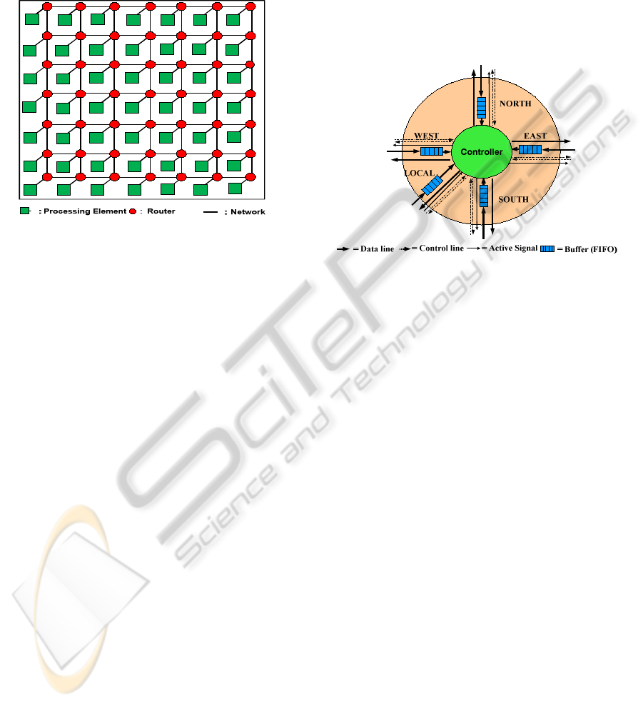
composed of n×n tiles, inter-connected by a 2-D
mesh network as depicted in Fig. 1. Each tile is
composed of a processing element (PE) and a router.
The router embedded into each tile is connected to
four neighbouring tiles and its local processing
element
Figure 1: A typical Mesh NoC architecture.
via channels. A channel consists of two
unidirectional point-to-point links between two
routers or between a PE and a router. For the 2-D
mesh, outer routers which are sometimes referred to
as peripheral routers, have one or two null
connections.
Compared to typical macro-networks, an on-chip
network is by far more resource limited. To
minimize the implementation cost, the on-chip
network should be implemented with little area
overhead. This is especially important for those
architectures composed of tiles with fine-level
granularity. Thus, instead of having huge memories
(e.g., SRAM or DRAM) as buffer spaces for those
routers/switches in the macro-network, it is more
reasonable to use registers as buffers for on-chip
routers. This leads to a much simpler power model
with little overhead compared to its macro-network
peer. A mesh design consists of connected routers
and wrappers, an interface for Processing Elements
(PEs). A sufficient number of routers must be
instantiated for a given size of a mesh. For example
in this paper, a 4 × 4 size mesh including 16 routers
is considered for implemented and cost analysis. The
mesh size, packet width, and depth of buffers are the
other important design parameters to be considered
when implementing and analysing a new architecture
on a 2-D mesh network.
3.1 Mesh Conventional Router
Prior to discussion of new router architecture, we
briefly explain how a conventional router uses
buffers to store packets. Fig. 2 shows the architecture
of a static router which has been used in DyNoC
(Bobda et al., 2005).
There are three main components in the
traditional router architecture, called Distributed-
Buffering (DB): five input FIFOs (buffers), control
Figure 2: Traditional router (DB) architecture.
logic, and five output arbiters. The router uses a
simple XY routing algorithm to route the packets. At
each input port, there is a FIFO associated with
control logic. The control logic consists of a routing
decision unit which determines the packet
forwarding using the routing algorithm. Each output
port is associated with an arbiter, which sends out
packets and controls signals. A round-robin
arbitration scheme is used to select only one output
packet if there are several packets that approach to
the same output port at a given time.
This type of router architecture is quite efficient
when the traffic rates are nearly the same in different
channels. However, due to the nature of real
applications, traffic rates are usually different in each
direction. In DB architecture, where the traffic
patterns are known, we can use the same architecture
but determine the buffer size of each channel
according to its traffic rate (Jingcao and Marculescu,
2004). However, this cannot work in all cases. For
example, according to this approach, we allocate the
largest buffer to the west channel of a router because
of its highest traffic rate compared to other channels,
and allocate the smallest buffer to the south input
channel where it has lowest traffic rate. If after a
period of time, the traffic rate on the west channel
decreases dramatically, and increases on the south
channel, the buffer on west side will be much less
AN EFFICIENT ROUTER ARCHITECTURE FOR NETWORK ON CHIP
407
utilised compared to the southern buffer where may
overflow repeatedly.
Therefore, in such cases that traffic rates are
dynamic because of running parameterisable
applications, fixed buffer allocation may not be
utilised efficiently.
3.2 New Router Architecture
In a dynamic system where the traffic rates are
unknown, in order to guarantee all arriving packets
will be routed through the router, the size of buffer
E
a
s
t
C
h
a
n
n
e
l
B
u
f
f
e
r
N
o
r
t
h
C
h
a
n
n
e
l
B
u
f
f
e
r
S
o
u
t
h
C
h
a
n
n
e
l
B
u
f
f
e
r
Figure 3: New router (PB) architecture.
router should be infinite. Due to physical constraints,
in any NoC router the size of buffers is limited.
However, while the size of buffer increases, latency
decreases and throughput improves.
Therefore we need to utilise limited buffer
resources maximally in order to improve the quality
of service in NoC. For this purpose, we need to
design a new router architecture where it can allocate
buffer sizes dynamically for different channels.
In a recent work (Jingcao and Marculescu, 2004),
buffer channels can borrow FIFO cells from their
adjacent channels, which is not flexible enough to
use free buffer resources at channels which are not
their neighbours. This is quite inefficient, in network
topologies such as honeycomb (Hemani et al., 2000),
where there are six channels in each router.
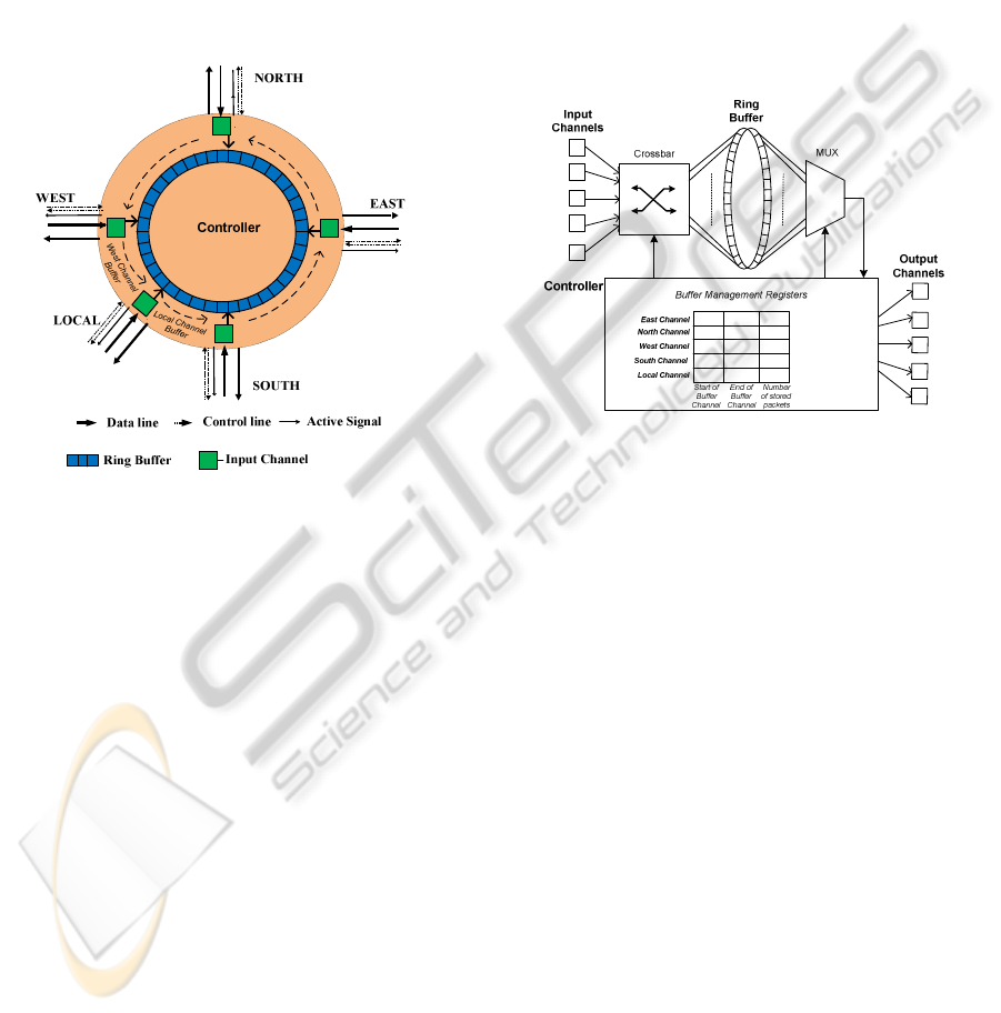
In this work, we design a fully flexible router
architecture, called Pool-Buffering (PB), where it
can allocate any available buffer from a pool to those
channels that need larger buffers regardless of their
positions.
For this purpose, our router architecture combines
buffer channels in a ring structure, which is more
flexible and has less complexity compared to (Matos
et al., 2009). Fig. 3 shows the basic architecture of
our ring based architecture which ensures all buffer
resources can be used on traffic demand of any input
channel.
For each input channel, two registers keeps head
and tails of its buffer in the ring buffer. Another
register for each buffer slot is dedicated to count the
number of stored packets in that buffer channel. Fig.
3 shows the initial buffer allocations to the channels,
while it can adapt itself according to traffic rate, by
shifting the buffer slots of channels clockwise. For
example, if the allocated slot to the east port of
Figure 4: PB router architecture.
router is full, the controller checks other slots clock
wise to identify empty cells in the ring. If the north
channel has free spaces, controller just shifts the
stored packets in east and north allocated buffers to
make space for the incoming packet at the east port.
Also, the address registers of both buffer slots will
be updated according to shift in the ring buffer.
Similarly, if controller finds the first free space in the
west channel buffer slot, the shift occurs in the east,
north
and west buffer slots and at the same time their
corresponding buffer address registers will be altered.
With this approach, the controller can make sure to
accommodate incoming packet to its maximum space
which may increase the quality of service in the NoC.
As shown in Fig. 3, a part of ring buffer is allocated
for the local channel to interface cores to the network
through router. It can be argued that there is no need of
the buffer allocation for the local interface since the
local processing core can queue larger number of
packets within its resources. It should be noted that
firstly this buffer allocation can be released on demand
of other input channels router. Secondly, some of
processing cores in NoCs are not complex enough to be
interfaced to the NoC through a wrapper with a buffer
channel. Therefore, in such cases if the router buffer is
full and even cannot queue the first outgoing packet
PECCS 2011 - International Conference on Pervasive and Embedded Computing and Communication Systems
408

from the processor, the processor has to be halted
immediately which increases latency in the whole
system. On the other hand, a buffer space, even a small
one allows the router to notify the processor to slow
down its packet transfer until there is enough resources
in the router to queue and route them.
In order to make sure full flexibility in shifting of
buffer channels, a crossbar medium is deployed to
realise of connection of input channels with every cell
in the ring buffer. The details of router interconnection
are shown in Fig. 4.
The packets in the ring buffer can be retrieved
through a multiplexer, which will be routed to the
correct output port towards its destination by the
controller. Moreover, as mentioned before, there are a
set of registers to keep record of each buffer slot and its
occupied cells. These registers form the table of buffer
management registers as shown in Fig. 4.
4 HARDWARE COST ANALYSIS
For hardware cost estimation, the proposed router is
developed at Register-Transfer-Level (RTL) in VHDL
language and implemented on a Xilinx Virtex-2
XC2V6000 FPGA. We have measured its power
consumption and area overhead for different ring
buffer sizes. For power dissipation measurements,
Xilinx XPower tool (Xilinx XPower) is used. These
results have been compared with the static router
developed in DyNoC (Bobda and Ahmadinia, 2005).
Figs.5, 6, 7 and 8 show power consumption, area
overhead and maximum frequency of the proposed
router compared to the static router for different
channel widths and buffer sizes.
0
500
1000
1500
2000
2500
16&816&16 32&832&16
Slices
ChannelWidth(bits) &Buffer Size
AreaOverhead
DB
PB
Figure 5: Comparison of area overhead of PB vs. DB
architecture.
Fig. 5 compares the area overhead of the proposed
router and the static router in terms of slices used in the
target FPGA for their implementation. The amount of
resource utilisation increases for both router when the
channel width of buffer sizes increases. As can be seen,
the channel width has more impact on the area
overhead compared to buffer size. This is due to
demand of more routing resources in case of increasing
channel width, while the buffer size has more impact
on memory usage than routing and controlling
resources.
In all cases, PB utilises more hardware resources
compared to that of DB. The area overhead of the PB
router is nearly double of that of DB architecture.,
when channel width is 16 bits and buffer size is 8.
However, this gap of resource area utilisation shrinks
when channel width or buffer size is increased. This is
because the ring buffer needs a more complex buffer
management in general, and most of area usage is
dedicated to its buffer manager, while the buffer depth
or channel width does not influence its controller
noticeably.
Although, the area overhead is more in the proposed
router, its memory usage has been greatly reduced, as
shown in Fig. 6. The main reason of its memory
efficiency is its buffer structure which can be shared
between all five ports, while in the DB architecture,
separate buffers are alloacted to each input channel.
Therefore, when the buffer size increases, it can be
seen that the area overhead of static router increases
dramatically, compared to PB router which its memory
usage increases linearly.
0
900
1800
2700
3600
4500
16&816&16 32&832&16
FlipFlops
ChannelWidth(bits) &Buffer Size
MemoryOverhead
DB
PB
Figure 6: Comparison of memory overhead of PB vs. DB
architecture.
Fig. 7 compares the maximum frequency of DB and
PB routers implemented on Xilinx FPGA. DB can
reach a higher frequency, because it uses separate
FIFOs which are connected to the controller with a
simple point-to-point medium at their heads and tails.
On the other hand, in PB router, the crossbar and
connection of every cells of ring buffer to the controller
creates longer path delays, hence reduces its maximum
frequency.
A very important cost factor of routers is their
power consumption (Xuning and Peh, 2003), which is
highlighted in Fig. 8. In comparison with the static
router, the power consumption of our proposed router
is considerably less, because the static router uses
much more flip-flops compared to the proposed router,
which are consuming power permanently due to the
AN EFFICIENT ROUTER ARCHITECTURE FOR NETWORK ON CHIP
409

clock. Therefore, power saving of our router is greater
when
0
20
40
60
80
100
120
140
160
180
200
16&816&16 32&832&16
MHz
ChannelWidth(bits) &Buffer Size
Speed
DB
PB
Figure 7: Comparison of maximum frequency of PB vs.
DB architecture.
the buffer size has increased and inevitably the number
of flip-flops goes up.
In order to monitor the effectiveness of the
proposed router architecture versus static router as well
the router proposed in (Matos et al., 2009), a
simulation is carried out under random patterns and
different source-destination pairs communicating at
different times. In the simulation, a network with 16
nodes (4x4) is modelled. In the NoC model, wormhole
packet switching is used, routing algorithm is XY
routing, and packet size is fixed to 16 bytes. Buffer size
is set to 8, and clock frequency in these simulations is
taken to be 100MHz. Therefore, by changing the router
model in the system, we have compared their quality of
service in terms of packet delivery.
Figure 9 shows the comparison of quality of service
in NoC with different router architectures. It can be
seen that by employing DB the quality of service of
NoC, in terms of blocked packets when buffer is full
decreases. However, the router proposed in (Jingcao
and Marculescu, 2004) increases the number of
delivered packets without any buffer blocking, since its
buffer manager tries to use buffers of adjacent channels
in the router, which can reduce the number of blocked
packets.
On the other hand, in the proposed router
architecture, the percentage of delivered packets is
higher than the static one as well as the one in (Matos
et al., 2009). This is due to the high flexibility of our
buffer management, which allows delivering packets to
its maximum buffer usage without any blocking delay.
Therefore, input channels can use the whole buffer of
router on high traffic load demand. So, the flexibility of
ring buffer makes the proposed router capable to
overcome the unblocked packet delivery rate of static
router and the router presented in (Matos et al., 2009).
0
200
400
600
800
1000
1200
1400
16&816&16 32&832&16
mW
ChannelWidth(bits) &Buffer Size
PowerConsumption
DB
PB
Figure 8: Comparison of power consumption of PB vs.
DB architecture.
5 PERFORMANCE EVALUATION
The performance of networks using the proposed PB
and DB router architectures has been studied using a
discrete-event simulator that performs a time-step
simulation of network operations at the flit level. Each
simulation experiment is run until the network reaches
its steady state; that is until a further increase in
simulated network cycles does not change the collected
statistics appreciably. Statistics gathering was inhibited
for the first 10000 messages to avoid distortions due to
the startup transient.
Extensive evaluation experiments have been performed
for several combinations of network sizes, message
lengths and available buffer space. For the sake of
specific illustration, latency results are presented for
the networks with N = 16 (4 X 4), N = 36 (6 X 6), and
N = 64 (8 X 8) nodes, M = 8 and M = 16 flits message
lengths and B=10(30), B=20(60) and B=40(120) flits
buffer size. Nodes generate traffic independently from
each other, via a Poisson process with a mean rate. A
generated message is sent to other nodes in the network
with equal probability. It takes one cycle for a flit to
cross a router from one input channel to an output
channel given that the channel is not blocked.
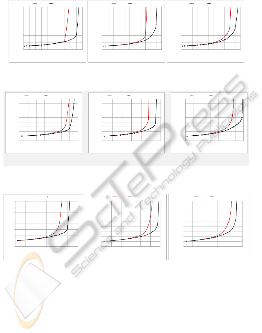
Graphs in Fig. 9 show the average message latency
in a mesh network of 16 nodes, 8 flits message length
and three different buffer space. The horizontal axis in
the figure represents the message generation rate of
every node per cycle while the vertical axis shows the
average message latency, respectively. This figure
reveals that PB performs almost the same as DB when
the network is under light to moderate traffic load.
However, PB provides lower message latency under
heavy traffic and even when the network starts to
approach saturation. Besides, the PB’s maximum
sustained load is about 20% higher than that of DB.
To investigate the scalability of each router’s
architecture, the network size is increased to 36 and 64
PECCS 2011 - International Conference on Pervasive and Embedded Computing and Communication Systems
410
0
20
40
60
80
100
120
0 0.01 0.02 0.03 0.04 0.05 0.06 0.07 0.08 0.09 0.1
Latency
(Cycle)
offeredload
(Message/Node/Cycle)
DB(B=10) PB(B=30)
0
20
40
60
80
100
120
0 0.010.020.030.040.050.060.070.080.09 0.1 0.11
Latency
(Cycle)
offeredload
(Message/Node/Cycle)
DB(B=20) PB(B=60)
0
20
40
60
80
100
120
0 0.010.020.030.040.050.060.070.080.09 0.1 0.11
Latency
(Cycle)
offeredload
(Message/Node/Cycle)
DB(B=40) PB(B=120)
(a) (b) (c)
Figure 9: Message latency in a mesh of 16 nodes, 8 flits message length, and buffer depth of 10, 20 and 40 flits for DB and
30, 60, and 120 for PB.
(a) (b) (c)
0
20
40
60
80
100
120
140
160
180
0 0.004 0.008 0.012 0.016 0.02 0.024 0.028
Latency
(Cycle)
offeredload
(Message/Node/Cycle)
Static(B=10) Proposed(B=30)
0
20
40
60
80
100
120
140
160
180
0 0.0055 0.011 0.0165 0.022 0.0275 0.033
Latency(Cycle)
offeredload
(Message/Node/Cycle)
Static(B=20) Proposed(B=6 0)
0
20
40
60
80
100
120
140
160
180
0 0.005 0.01 0.015 0.02 0.025 0.03 0.035
Latency
(Cycle)
offeredload
(Message/Node/Cycle)
Static(B=4 0) Proposed(B=120)
Figure 10: Message Latency in a (a)36-node mesh, 16 flits message length and buffer depth of 20 and 66 flits for DB and
PB, (b) 36-node mesh. 16 flits message length and buffer depth of 40 and 133 flits for Db and PB. (c) 64-node mesh, 32
flits.
0
20
40
60
80
100
120
140
160
0 0.004 0.008 0.012 0.016 0.02 0.024
Latency
(Cycle)
offeredload
(Message/No de/Cy cle)
DB(B=10) PB(B=35)
0
20
40
60
80
100
120
140
160
180
0 0.004 0.008 0.012 0.016 0.02 0.024
Latency
(Cycle)
offeredload
(Message/Nod e/Cycle)
DB(B=20) PB(B=70)
0
20
40
60
80
100
120
140
160
180
0 0.004 0.008 0.012 0.016 0.02 0.024 0.028
Latency
(Cycle)
offeredload
(Message/Nod e/Cycle)
DB(B=40) PB(B=140)
(a) (b) (c)
Figure 11: Message latency in a 64-node mesh, 16 flits message length, and buffer depth of 10, 20 and 40 flits for DB and
35, 70, and 140 flits for PB.
nodes in Figures 10 and 11. Figure 10 shows the
average message latency in a mesh network of 36
nodes and 16 flits message length. The available buffer
space for every node in each dimension is considered
to be 10, 20, and 40 flits in the conventional router
architecture. In adaptive router architecture, every node
has 30, 60 and 120 flits ring buffer space, respectively.
In all these graphs, the adaptive architecture still
performs better than the static router under heavy
traffic; message latency is almost cut in half in the
proposed architecture router close to the saturation
point. The maximum sustained load in the adaptive
router architecture is also increased by almost 20%.
Figure 11 also confirms the proposed adaptive
router performance improvement in a network of 64
nodes, 16 flits message length and the same number of
buffer as correspondingly considered in Figure 10.
6 CONCLUSIONS
A new router architecture for NoCs has been
AN EFFICIENT ROUTER ARCHITECTURE FOR NETWORK ON CHIP
411

proposed in this paper. In a traditional NoC design,
the router architectures have fixed allocated buffer
space for each input channel. With communication
in future heterogeneous SoC architectures, especially
with running different applications with different
traffic patterns at different times, this will prove
highly inefficient due to the router resources not
getting utilised effectively, causing wastage of buffer
capacities. The proposed router architecture
endeavours to solve this problem, by using a fully
flexible ring buffer structure which can be shared
between all channels of router. The buffer size of
each channel will be allocated from the ring buffer
which can vary from a single buffer unit, when there
is no traffic on that channel, up to the whole buffer
length of the ring buffer which represents all
dedicated buffer resources of the router. Therefore,
the proposed router allocates buffer sizes at runtime
according to the traffic rate of each channel. This
router architecture enables utilisation of all available
buffer resources effectively and improves the quality
of service in the NoCs. A simple mechanism has also
been proposed to avoid deadlock and to make sure
that there is at least an escape channel for the
blocked messages to proceed.
Although RTL implementation results showed an
increase of area, this architecture proved its
superiority in terms of power consumption as well as
memory overhead compared to the DB architecture.
Moreover, our extensive simulation study has shown
the effectiveness of this approach in improving the
network performance. In all simulations scenarios,
the proposed architecture has
experienced lower
message latency under heavy moderate to traffic and
even when the network starts to approach saturation.
Furthermore, it has been shown that the maximum
sustained load of the proposed router is up to 20%
higher than that of a traditional router.
REFERENCES
International Technology Roadmap for Semiconductors
web site http://public.itrs.net.
W. J. Dally and B. Towles, "Route Packets, Not Wires:
On-Chip Interconnection Networks," in Proceedings
of the Design Automation Conference (DAC), 2001.
P. Guerrier and A. Greiner, "A generic architecture for on-
chip packet-switched interconnections," in
Proceedings of the Design, Automation and Test in
Europe Conference and Exhibition (DATE), pp. 250-
256, 2000.
A. Hemani, A. Jantsch, S. Kumar, A. Postula, J. Öberg, M.
Millberg, and D. Lindqvist, “Network on a Chip: An
architecture for billion transistor era”, Proceeding of
the IEEE NorChip Conference, 2000.
L. Benini and G. D. Micheli. Networks on Chip: A New
SoC Paradigm. IEEE Computer, 35(1):70–78, 2002.
C. Bobda, A. Ahmadinia, M. Majer, J. Teich, S. Fekete,
and J. Van der Veen. DyNoC: A Dynamic
Infrastructure for Communication in Dynamically
Reconfigurable Devices. In Field-Programmable
Logic and Applications, International Conference,
pages 153–158, 2005.
C. Xuning and L. S. Peh, "Leakage power modeling and
optimization in interconnection networks," in
Proceedings of the International Symposium on Low
Power Electronics and Design (ISLPED), pp. 90-95,
2003.
H. Jingcao and R. Marculescu, "Application-specific
buffer space allocation for networks-on-chip router
design," in Proceedings of the IEEE/ACM
International Conference on Computer Aided Design
(ICCAD), pp. 354-361, 2004.
C. Bobda and A. Ahmadinia, Dynamic interconnection of
reconfigurable modules on reconfigurable devices,
Design and Test of Computers IEEE 22 (5) (2005),
pp. 443–451.
J. H. Bahn, S. E. Lee, and N. Bagherzadeh, "Design of a
router for network-on-chip," International Journal of
High Performance Systems Architecture 2007 - Vol.
1, No.2 pp. 98 - 105.
M. Kreutz, A. Cesar, M. Luigi, C. Flavio, W. Altamiro
and A. Susin, “Design space exploration comparing
homogeneous and heterogeneous network-on-chip
architectures”, Proc. of Symposium on Integrated
Circuits and System Design, 2005, pp. 190–195.
S. Lee, N. Bagherzadeh, "Increasing the Throughput of an
Adaptive Router in Network-on-Chip (NoC), " in the
Proc. of Int'l Conference on Hardware/Software
Codesign and System Synthesis (CODES+ISSS), Oct.
2006.
B. Ahmad, A. Ahmadinia, and T. Arslan. Dynamically
Reconfigurable NoC with Bus Based Interface for
Ease of Integration and Reduced Design Time. In
Proc. of NASA/ESA Conference on Adaptive
Hardware and Systems. pp. 309-314, June 22-25,
2008.
M. A. Al Faruque, T. Ebi, J. Henkel: "ROAdNoC:
Runtime Observability for an Adaptive Network on
Chip Architecture", in Int'l Conference on Computer-
Aided Design. ICCAD 2008. 543-548.
D. Matos, C. Concatto, A. Kologeski, L. Carro, F.
Kastensmidt, A. Susin, and M. Kreutz. Adaptive
router architecture based on traffic behavior
observability. In Proc.s of intl. Workshop on Network
on Chip Architectures, New York, December 2009.
Xilinx XPower, http://www/xilinx.com
PECCS 2011 - International Conference on Pervasive and Embedded Computing and Communication Systems
412
