
FACE RECONSTRUCTION WITH STRUCTURED LIGHT
John Congote
1,2
, I
˜
nigo Barandiaran
1
, Javier Barandiaran
1
, Marcos Nieto
1
1
Vicomtech Research Center, Donostia - San Sebastian, Spain
Oscar Ruiz
2
2
CAD CAM CAE Laboratory, EAFIT University, Medell
´
ın, Colombia
Keywords:
3D Reconstruction, Structured light, Gray codes, Depthmap.
Abstract:
This article presents a methodology for reconstruction of 3D faces which is based on stereoscopic images of
the scene using active and passive surface reconstruction. A sequence of Gray patterns is generated, which are
projected onto the scene and their projection recorded by a pair of stereo cameras. The images are rectified
to make coincident their epipolar planes and so to generate a stereo map of the scene. An algorithm for
stereo matching is applied, whose result is a bijective mapping between subsets of the pixels of the images.
A particular connected subset of the images (e.g. the face) is selected by a segmentation algorithm. The
stereo mapping is applied to such a subset and enables the triangulation of the two image readings therefore
rendering the (x,y,z) points of the face, which in turn allow the reconstruction of the triangular mesh of the
face. Since the surface might have holes, bilateral filters are applied to have the holes filled. The algorithms
are tested in real conditions and we evaluate their performance with virtual datasets. Our results show a good
reconstruction of the faces and an improvement of the results of passive systems.
1 INTRODUCTION
1.1 Mathematical Context
In general, surface reconstruction from optical sam-
ples requires a function G relating pixels in an image
of the scene A ×B (A,B ⊂ N) with points p ∈ R
3
. This
function, G : A ×B → R
3
, is an injection since the im-
age only records the visible part of the scene. G is not
an onto function, as there are many points p ∈ R
3
for
which there is no pixel (i, j) ∈ A × B in the image that
records them.
Once this geometry function G is known, it is
relatively simple to build a triangular mesh of the
portion of the object visible in the image. Under
a threshold of geometrical proximity, G(i, j), G(i +
i, j),G(i + 1, j + 1) may be considered the vertices
of a triangular facet of the sought surface M. More-
over, the triangles being natural neighbors to triangle
t = [G(i, j),G(i + i, j), G(i + 1, j + 1)] are the ones in-
volving pixels (i, j + 1),(i + 2, j + 1),(i, j − 1), again,
under thresholds of geometrical proximity. Stitching
the different M triangular meshes originated in differ-
ent views of the scene is known as zippering, and is
not in the scope of our article. Literature on the topic
might be found in (Greg Turk, 1994), (Marras et al.,
2010) and (Shen et al., 2004).
The discussion in this article involves two images,
which may be labeled, without losing generality, as
right and left, I
R
and I
L
. Simplifying the discussion,
a color image is a mapping I : A × B → [0,255]
3
.
For example, I(i, j) = (143,23,112) means that the
color registered in the pixel (i, j) of I corresponds to
Red=143, Green=23 and Blue=112. A grey scale im-
age has the form I(i, j) = (k,k,k) due to the fact that
in it the Red, Green and Blue graduations are identical
(k ∈ [0, 255]).
Let S
L
and S
R
be the coordinate systems associ-
ated to images Left and Right, respectively. In the
general configuration of the set-up, S
L
and S
R
such
that (1) the Z axis of the coordinate system is normal
to the capture plane of the image, and (2) the two cam-
eras point to a common point p ∈ R
3
. In this article
we assume that the images are rectified. This means,
both of them have been rotated inside their own X −Y
plane (i.e. rotation around the Z axis of the image) in
such a manner that the epipolar plane of the set-up is
seen as the plane y = E
e
in both images. That means,
149
Congote J., Barandiaran I., Barandiaran J., Nieto M. and Ruiz O..
FACE RECONSTRUCTION WITH STRUCTURED LIGHT.
DOI: 10.5220/0003371401490155
In Proceedings of the International Conference on Computer Vision Theory and Applications (VISAPP-2011), pages 149-155
ISBN: 978-989-8425-47-8
Copyright
c
2011 SCITEPRESS (Science and Technology Publications, Lda.)

Figure 1: Results of the algorithm with the virtual dataset.
Smooth surfaces are obtained with wider baselines.
the epipolar plane is seen as the same horizontal line
in both images. We call the rectified images I
R
and I
L
and their rectified and their rectified coordinate sys-
tems S
L
and S
R
, respectively.
Let us consider a point p ∈ R
3
recorded in both
images I
R
and I
L
. Because the previous assumptions
we have that G
L
(i, j) = p and G
R
(i,k) = p. This
means, the point p appears in the same row i of pixels
in both images. The value |k − j| is an offset that only
occurs in the same pixel row of both images. Since
we know that pixels (i, j) in image I
L
and (i,k) = p
in image I
R
record the same point p ∈ R
3
, the point p
can be recovered by a usual triangulation procedure.
1.2 Informal Context
Human face reconstruction is a common problem in
computer vision and computer graphics (Stylianou
and Lanitis, 2009), where one possible objective is
the generation and animation of a virtual model of it.
The face is one of the most important identification
regions of the human body, presenting commensurate
technical challenges (Zhao et al., 2003). A correct re-
construction of human faces is a precondition to both
augmented reality and face recognition.
3D surface reconstruction may be achieved by
both pasive and active methods. pasive ones do not
change the environment in the process of reconstruc-
tion. Even thought pasive methods obtain very good
results, their setups are very expensive because they
required a very high resolution required for obtaining
reasonable results(Beeler et al., 2010).
Active systems modify or adapt the environment
during the capture process. Our active system uses
the projection of a light pattern (i.e structured light),
which is widely used for face surface reconstruction.
In structured light systems any change on the setup
requires new algorithms for face (surface) reconstruc-
tion.
The 3D surface reconstruction system imple-
mented and informed in this article is part of a system
used for full body reconstruction with visual hull al-
gorithm (Haro and Pard
´
ıs, 2010). Our setup applied
to a face-body model produces a triangular mesh with
high detail in the face region and low detail in the rest
of the body. The reason for this differential resolution
is that, while for the face region one requires high fre-
quency details (e.g. texture of the skin), for the rest of
the body such details are not required in our applica-
tions.
This article presents a system for face reconstruc-
tion which articulates non-proprietary hardware and
our own software to obtain geometrical information
from two images (possibly originated in 3D video -
conference set ups). Our system also recovers the 3D
geometry form the body region, although intention-
ally using lower resolution for neighborhoods other
than the face.
This paper, Section 2 reviews previous works in
face reconstruction. Section 3 presents the method-
ology implemented, including generation of the light
patterns, capture, segmentation and reconstruction.
Section 4 discusses the hardware set-up for the ex-
periment and its configuration. Section 5 presents the
results of the 3D surface reconstruction set-up and
algorithms, and evaluates the reconstructed models
against with real data. Section 6 concludes the work
and proposes the future actions in this domain.
2 RELATED WORK
Face reconstruction is a widely studied topic. (Pighin
and Lewis, 2005) presents a tutorial on face re-
construction, describing different problems and ap-
proaches from an artistic point of view, looking for
a correct representation of the face and its expres-
sions in multi-media. (Stylianou and Lanitis, 2009)
presents a survey of 3D face reconstruction methods,
classifying them in three different categories: single
image, stereo images and videos.
pasive systems are commonly used for face recon-
struction. One of the advantages of these systems is
their non interaction with the environment, allowing
to capture the geometry without interfering with other
systems. (Onofrio et al., 2005) uses a system with
four calibrated cameras applying a multi - view algo-
rithm. A stochastic model is generated for the identifi-
cation of the geometry, by minimizing a cost function.
(Leclercq et al., 2005) compares different stereo al-
gorithms for face reconstruction, and proposes an ap-
propiate geometrical configuration of cameras to ob-
tain accurate results. (Alexander et al., 2009) presents
a complex setup to a high resolution face reconstruc-
tion system. The methodology is based on an iterative
reconstruction of the face by incrementing the size of
the image and the number of stereo pairs used in each
step. (Beeler et al., 2010) extends the approach pro-
posed in (Alexander et al., 2009) by adding a post-
processing step that modifies the geometry of the face
VISAPP 2011 - International Conference on Computer Vision Theory and Applications
150

by using a texture, assuming that small dark regions
of the face represent small hollows. This approach
obtaining a more rich geometry.
Structured light for 3D reconstruction have been
study for several years. The information obtained
with this kind of systems is already being used
as ground truth data for the evaluation of pasive
reconstruction systems, such as stereo algorithms
(Scharstein and Szeliski, 2003). An extensive survey
of structured light 3D reconstruction approaches can
be found in (Salvi et al., 2010), where a classifica-
tion of different coding techniques are presented and
evaluated. They identify the best coding approach for
each one of the possible scenario configurations such
as static o moving scenearios or if the light conditions
are controled.
Real time capture of facial expresions is also an
important feature in some systems. Several prob-
lems have to be addresed to accomplish this objec-
tive. One of these problems is the difficulty of pro-
jecting several patterns for a reconstruction in non
static scenes where small moves generate artifacts
in the reconstructions, so other patterns have been
employed which uses color models as (Tsalakanidou
et al., 2005) which allows a denser codification of the
pattern, also single frame reconstruction with 2D cod-
ing is possible(Chen et al., 2008). Another problem is
hardware calibration to obtain several frames per sec-
ond with a correct synchronization process between
the projector and the cameras. An accepted syn-
chronization approach can be found in (Zhang et al.,
2006). Finally, for a correct pattern codification of
time variant patterns, a motion compensation should
be implemented. This issue is especially critical for
face reconstruction systems, where the person being
reconstructed could move in a involuntary way,during
acquisition (Weise et al., 2007)
3 METHODOLOGY
Our algorithm of face reconstruction uses a set of
stereo images captured at the same moment when a
pattern is projected into the face. The images are cap-
tured in a setup previously calibrated. We assume
that the object does not move between the different
captures and the face is assumed to be a smooth sur-
face without hair or beard and without highlight re-
flections. The result is a mesh of triangles correctly
positionated in the space which represent the face re-
gion.
3.1 Stereo Calibration
Stereo calibration refers to the task of finding the
relative pose between the cameras of a stereo pair.
The objective is to feed subsequent stereo rectification
processes that align the images such that the epipo-
lar lines are horizontal and thus matching algorithms
for 3D reconstruction can be implemented as one-
dimensional searches.
Typically, stereo calibration is carried out by
means of finding a number of point-correspondences
between the images of the pair and retrieving the fun-
damental matrix. Let x be the image of a 3D point in
the left image, and x
0
the image of the same point in
the right image. The fundamental matrix restricts the
position of x
0
to the epipolar line associated to x, such
that x
0>
Fx = 0. It has been shown (Hartley and Zis-
serman, 2004), that the knowledge of the fundamental
matrix can be used to retrieve the projection matrices
of the two cameras of the pair, up to a projective am-
biguity that can be solved with known restrictions of
the camera.
Besides, images captured by real cameras show
some tangential and radial distortion, which can be
corrected applying the following functions:
u = p
x
+ (u − px)(1 + k
1
r + k
2
r
2
+ k
3
r
3
+ .. .)
v = p
y
+ (v − py)(1 + k
1
r + k
2
r
2
+ k
3
r
3
+ .. .)
where r
2
= (u − p
x
)
2
+ (v − p
y
)
2
and k
1
,k
2
,k
3
,. .. are
the coefficients of the Taylor expansion of an arbitrary
radial displacement function L(r).
Parameter identification of the camera stereo pair
is extracted from the calibration information of the
full body reconstruction setup; which is further ex-
plained in (Ronda et al., 2008). For our purposes we
select the camera pair which are focused to the face
region of the body, and we follow a 3D stereo recon-
struction process with them.
3.2 Pattern Generation
Pattern generation refers to the task of creating of a set
of synthetic binary images to be projected as struc-
tured light in the scene. The objetive is to identify
the coordinates of the projected pattern in the image
scene and thus allowing a point matching algorithm
to become independent of the color in the captured
scene.
The used patterns are represented as a matrix of
boolean values. Let P be a matrix of M columns and
N rows thus P = {P
m,n
∈ {0, 1}} with 0 < m < M and
0 < n < N. Let C be a matrix of the same dimensions
of P thus C = {C
m,n
∈ (0,M) ⊆ N}. The restriction of
FACE RECONSTRUCTION WITH STRUCTURED LIGHT
151

Algorithm 1: Gray function to convert from binary
to gray code.
Input: bin
Output: gray
return bin
(bin/2)
Algorithm 2: Gray function to convert from Gray
code to binary.
Input: gray
Output: bin,nPat
ish,ans,idiv ∈ N
ish ← 1
ans ← gray
while 1 do
idiv ←
ans
ish
ans ← ans ⊕ idiv
if idiv ≤ 1 ∨ ish = 32 then
return ans
end
ish ← ish × 2
end
the number of values in the matrix C is the same that
the number of columns allows the correct identifica-
tion of the column in the images. Let g be a function
such as g : N → N which is bijective and transforms
the numbers from binary representation to Gray repre-
sentation as described in algorithm 1, the inverse Gray
function g
−1
is described in algorithm 2. The number
of images to be projected depends of the number of
columns of the matrix C, so nPat =
d
log
2
M
e
The nPat patterns represented by the matrix P are
generated as follows:
P
i
j,k
= g( j) • 2
i
where 0 < i < nPat represent the number of the pat-
tern, j,k the coordinates in the matrix P. The pattern
structure can be depicted as a sequence of columns as
can be visualized in the figure 2. The nature of this
kind of patterns is 1D because the calibration setup
already give us an epipolar constrain of the images.
Therefore it is not neccesary to use of 2D patterns in
this case.
Figure 2: Gray code.
3.3 Pattern Recognition
Pattern recognition refers to the task of creating a pair
of images which maps the position of the projected
patterns P in the set of stereo pair of images. The
objetive is the identification of the projected pattern in
the set of images, and calculate the value of the matrix
C for each pixel. This matrix allow the point matching
algorithm to become unambiguous since each point in
the maps is labeled uniquely in each epipolar line.
Let s = L,R be matrices of W columns and H
rows, thus L = {L
w,h
∈ (0, 255)} with 0 < w < W and
0 < h < H. The matrices L and R represent the in-
formation of the stereo pair cameras in grayscale. Let
O = {O
w,h
∈ (0, M)} be the decode maps OL, OR. Let
t : (0, 255) → {0, 1} be a threshold function which bi-
narizes the images L and R. The threshold value could
be calculated with the Otsu algorithm as explained in
(Kramer et al., 2009) or by means of calculating the
albedo of the images with the process described in
(Scharstein and Szeliski, 2003) where each pattern is
projected two times, each one with the original ver-
sion and their negative.
O
s
m,n
= g
−1
_
i
t
s
i
m,n
· 2
i
!
As shown in figure 3 the set of L and R images
are binarized. Stereo reconstruction images are com-
bined, and a unique map OL and OR is processed. The
maps should be rectified as shown in figure 4: this
rectification process is possible because the camera
information is already known as explained in section
3.1.
3.4 Stereo Reconstruction
Stereo reconstruction task calculates the point corre-
spondence between two images. The objective is to
calculate the 3D point coordinates of each pixel in the
stereo images. The previous steps of the algorithm
such as the stereo calibration assures the epipolar con-
strain. Pattern generation process gives the color in-
dependence of the images. Pattern recognition maps
the set of images into a map without ambiguities. For
dense depthmap calculation we used a simple box
filter algorithm, based on sum of square diferences
SSD and a Winner Takes All WTA for pixel selection
(Scharstein and Szeliski, 2002).
Let D be a matrix of W columns and H rows, thus
D = {D
w,h
∈ N}. where D describes the pixel differ-
ence between the same point in the image L and R.
The identification of the correct disparity the follow-
ing function is applied.
D
m,n
= minarg
l
(SSD(OL,OR, m,n,l))
VISAPP 2011 - International Conference on Computer Vision Theory and Applications
152
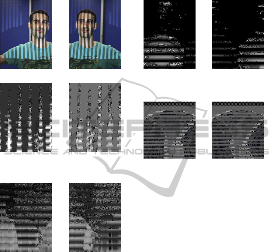
(a) Left camera capture (b) Right camera capture
(c) Left binarization (d) Right binarization
Figure 3: Stereo images captured from the cameras and
their result of the threshold function.
(a) Left Gray decoded (b) Right Gray decode
Figure 4: O maps of the images, the Gray value in each pixel
represents the value of the C matrix in the stereo images.
SSD(L, R,m,n, l) =
m+b
∑
e=m−b
n+b
∑
f =n−b
L
e, f
− R
e, f +l
2
The figure 5 shows the result of the disparity maps DL
and DR. The identification of wrong matched points
is carried out by applying process such as cross check-
ing and joint bilateral filter. It is assumed that the
biggest connected region represents the face, then a
max blob algorithm is applied to filter regions outside
the face. The mesh is generated by joining adjacent
pixels in the image with their 3D coordinates. The
topology of the mesh is correct since the difference
between the coordinates of adjacent pixels are small.
(a) Left disparity (b) Right disparity
Figure 5: Stereo reconstruction of the face, the disparity
images for the L and R.
(a) Visual Hull (b) Structured Light
Figure 6: 3D face reconstruction.
4 SETUP CONFIGURATION
As our algorithm is part of a bigger chain of process
where a full body reconstruction process is done. We
tried to mantain the same setup for our algorithm,
even we tried to use a pasive system for face recon-
struction, the resolution obtained were insuficient to
fulfill our needs. Then, we put a stereo camera setup
with a projector in the middle of the cameras. We
identified that a small distance between the cameras
does not give enough information for recovering 3D
positions accurately. In opposite, a wide baseline be-
tween cameras generates occlusion regions, althought
projection information is used for hole filling in post
processing step.
The cameras used where tested with different res-
olutions, 1024x768, 1240x960 and 1600x1200. Fi-
nally, the resolution was set to 1240x960. Also, the
projector were defined at a resolution of 800x600 be-
cause an increase of resolution generates very high
frecuency patterns, that are very difficult to identify
accurately at that resolution. We found that a mini-
mum width of 4 pixels for each column of the pattern
is necesary for a correct identification.
Different kind of binary patterns were used. Gray
pattern generates the best results. Using binary or go-
FACE RECONSTRUCTION WITH STRUCTURED LIGHT
153
lay patterns shows in some aspects imposible to gen-
erate a workable results. In this way, we didn’t con-
sider these methods for the final version, and used
only Gray codes. The binarization of the images
present one of the biggest problems of the structured
light setup. We used the Otsu method but it exhibits
some problems, such as high sensitivity to areas of
specular reflection. We finally choose the projection
of the negative images with good results and a thresh-
old t with a value of the half of the range of the gray
image.
5 RESULTS
The evaluation of the algorithm presents several prob-
lems since the groundtruth information it is not avail-
able. However, we implemented a virtual environ-
ment which resembles a real setup. This approach
allowed us to test our method and validate our results.
We use Blender software for the generation of the
setup and the identification of the groundtruth data,
as shown in figure 8. The groundtruth was defined
as a normalized depthmap with values between 0 and
255 using all the posible values in the image format
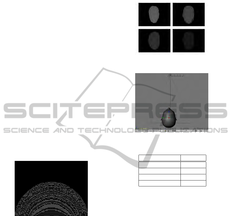
as shown in the figure 7.
Figure 7: Ground truth depthmap image of a face.
Different camera positions were tested in our vir-
tual setup, for the identification of the best baseline
distance. The results obtained with the algorithm are
shown in the figure 8. and the position of the cameras
are shown in the figure 9.
The groundtruth information and the results of the
algorithm show a difference in scale, but not in posi-
tion. We measured the difference of the results and the
groundtruth with a image correlation algorithm. The
correlation gives us a value between the range of 0 and
1 where 0 is a bad results and 1 is the groundtruth.
The table 1 presents the correlation values obtained
for different camera position, and the figure 1 shows
the 3D mesh generated.
Figure 8: Result from the different cameras in the virtual
setup.
Figure 9: Camera positions for virtual framework.
Table 1: Correlation Results.
Baseline distance Value
1 0.904372
2 0.938449
3 0.958089
4 0.974051
6 CONCLUSIONS AND FUTURE
WORK
We present a methodology for face reconstruction in
a mixed enviroment of active-pasive setup. Structured
light shows a quality improvement against the results
obtained with pasive setups. Time multiplexing cod-
ification has the problem of motion between the cap-
tured images generating a waving efect in the recon-
structions. Even robust algorithms of point matching
for dense depthmaps were tested there were no real
improvement in the results. We will try with color or
2D patterns which only requires one exposition that
present a better aproach for the reconstruction of faces
since the motion problem is not present.
ACKNOWLEDGEMENTS
This work has been partially supported by the Spanish
VISAPP 2011 - International Conference on Computer Vision Theory and Applications
154

administration agency CDTI, under project CENIT-
VISION 2007-1007. CAD/CAM/CAE Laboratory at
EAFIT University and the Colombian Council for
Science and Technology – COLCIENCIAS –.
REFERENCES
Alexander, O., Rogers, M., Lambeth, W., Chiang, M., and
Debevec, P. (2009). The digital emily project: pho-
toreal facial modeling and animation. In ACM SIG-
GRAPH 2009 Courses, SIGGRAPH ’09, pages 12:1–
12:15, New York, NY, USA. ACM.
Beeler, T., Bickel, B., Beardsley, P., Sumner, B., and Gross,
M. (2010). High-quality single-shot capture of fa-
cial geometry. ACM Trans. on Graphics (Proc. SIG-
GRAPH), 29(3).
Chen, S., Li, Y., and Zhang, J. (2008). Vision processing for
realtime 3-D data acquisition based on coded struc-
tured light. Image Processing, IEEE Transactions on,
17(2):167–176.
Greg Turk, M. L. (1994). Zippered polygon meshes from
range images. In ACM SIGGRAPH. Computer Graph-
ics Proceedings, Annual Conference Series, pages
311–318.
Haro, G. and Pard
´
ıs, M. (2010). Shape from incomplete sil-
houettes based on the reprojection error. Image Vision
Comput., 28:1354–1368.
Hartley, R. I. and Zisserman, A. (2004). Multiple view
geometry in computer vision. Cambridge University
Press.
Kramer, P., Boto, F., Wald, D., Bessy, F., Paloc, C., Cal-
lol, C., Letamendia, A., Ibarbia, I., Holgado, O., and
Virto, J. (2009). Comparison of segmentation al-
gorithms for the zebrafish heart in fluorescent mi-
croscopy images. In Bebis, G., Boyle, R., Parvin,
B., Koracin, D., Kuno, Y., Wang, J., Pajarola, R.,
Lindstrom, P., Hinkenjann, A., Encarnacao, M. L.,
Silva, C. T., and Coming, D., editors, Advances in Vi-
sual Computing, Lecture Notes in Computer Science
(LNCS), pages 1041–1050, Las Vegas, Nevada, USA.
Springer.
Leclercq, P., Liu, J., Woodward, A., and Delmas, P. (2005).
Which stereo matching algorithm for accurate 3d face
creation. In Klette, R. and Zunic, J., editors, Combina-
torial Image Analysis, volume 3322 of Lecture Notes
in Computer Science, pages 690–704. Springer Berlin
- Heidelberg. 10.1007/978-3-540-30503-3
53.
Marras, S., Ganovelli, F., Cignoni, P., Scateni, R., and
Scopigno, R. (2010). Controlled and adaptive mesh
zippering. In GRAPP - International Conference in
Computer Graphics Theory and Applications.
Onofrio, D., Tubaro, S., Rama, A., and Tarres, F. (2005). 3D
Face Reconstruction with a four camera acquisition
system. In Int’l Workshop on Very Low Bit-Rate Video
Coding.
Pighin, F. and Lewis, J. P. (2005). Introduction. In ACM
SIGGRAPH 2005 Courses, SIGGRAPH ’05, New
York, NY, USA. ACM.
Ronda, J. I., Vald
´
es, A., and Gallego, G. (2008). Line ge-
ometry and camera autocalibration. J. Math. Imaging
Vis., 32:193–214.
Salvi, J., Fernandez, S., Pribanic, T., and Llado, X. (2010).
A state of the art in structured light patterns for surface
profilometry. Pattern Recognition, 43(8):2666 – 2680.
Scharstein, D. and Szeliski, R. (2002). A taxonomy and
evaluation of dense two-frame stereo correspondence
algorithms. Int. J. Comput. Vision, 47(1-3):7–42.
Scharstein, D. and Szeliski, R. (2003). High-accuracy
stereo depth maps using structured light. In Com-
puter Vision and Pattern Recognition, 2003. Proceed-
ings. 2003 IEEE Computer Society Conference on,
volume 1, pages I–195 – I–202 vol.1.
Shen, C., O’brien, J., and Shewchuk, J. (2004). Interpolat-
ing and approximating implicit surfaces from polygon
soup. In ACM Transactions on Graphics, pages 896–
904. ACM Press.
Stylianou, G. and Lanitis, A. (2009). Image based 3d face
reconstruction: A survey. International Journal of Im-
age and Graphics, 9(2):217–250.
Tsalakanidou, F., Forster, F., Malassiotis, S., and Strintzis,
M. G. (2005). Real-time acquisition of depth and color
images using structured light and its application to 3d
face recognition. Real-Time Imaging, 11(5-6):358 –
369. Special Issue on Multi-Dimensional Image Pro-
cessing.
Weise, T., Leibe, B., and Gool, L. V. (2007). Fast 3d scan-
ning with automatic motion compensation. In IEEE
Conference on Computer Vision and Pattern Recogni-
tion (CVPR’07).
Zhang, S., Royer, D., and Yau, S.-T. (2006). High-
resolution, real-time-geometry video acquisition. In
ACM SIGGRAPH 2006 Sketches, SIGGRAPH ’06,
New York, NY, USA. ACM.
Zhao, W., Chellappa, R., Phillips, P. J., and Rosenfeld, A.
(2003). Face recognition: A literature survey. ACM
Comput. Surv., 35:399–458.
FACE RECONSTRUCTION WITH STRUCTURED LIGHT
155
