
VIRTUAL EXHIBITION BUILDER
Jorge Carvalho Gomes, Maria Beatriz Carmo and Ana Paula Cláudio
Faculdade de Ciências da Universidade de Lisboa, Lisboa, Portugal
Keywords: Virtual Exhibition, Virtual Museum, X3D, Xj3D.
Abstract: Virtual visits on the Web are an important means to publicize a museum collection and attract visitors.
Software applications for building virtual exhibitions, in addition to being tools to create content for virtual
visits, may help the staff of a museum to conceive and mount exhibitions. This paper presents the Virtual
Exhibition Builder, an interactive software tool aimed at the creation of virtual exhibitions, given a 3D
model of the exhibition space in an X3D file and a set of information about the artworks that are to be
exposed. The development of this tool involves inputs proposed by museum experts.
1 INTRODUCTION
Museums located around the world are open to
remote, on-line visitors through the World Wide
Web, spreading their collections and attracting
visitors to the museum itself.
Offering 3D virtual exhibitions may provide a
sense of immersion inside the exhibition space and
allow free navigation. They require the creation of
the virtual model of the exhibition space and the
placement of the artworks inside it. The latter task
should be performed by museum experts, which
seldom include information technology specialists.
Thus an interactive tool for assisting the placement
of artworks in selected locations, besides being
useful to create virtual exhibitions, can also be quite
a valuable auxiliary tool to mount a new exhibition.
Some tools have been proposed to help a
museum curator to conceive and mount an
exhibition (Hrk, 2001; Wojciechowski, 2004;
Katalabs).
In previous work (Semião, 2008), an application
was conceived aiming to support the creation of
virtual exhibitions by the museum curator. It was
based on Web3D technology (Web3D), generating
3D environments in X3D. This prototype had some
limitations and to overcome them, a new version of
the tool with additional features was implemented
(Gomes, 2010). This tool was presented to museum
experts to get advice about the functionalities that
should be provided and, as a result, it was updated
taking into consideration their observations. This
paper presents this revised version, called Virtual
Exhibition Builder: in section 2 are referred the
opinions given by museum experts; section 3
describes the application; and in section 4 are drawn
conclusions and is indicated the future work.
2 INPUT FROM A MUSEUM
TEAM
The new application was presented to the director of
the City Museum of Lisbon Town Council and to
her team. Throughout the year, this museum presents
several temporary exhibitions, along with its
permanent collection.
The functionalities of the new application
comprised: the selection of the surfaces that could
exhibit artworks; the placement of 2D and 3D
artworks and removable structures, such as dividing
walls to dispose paintings or plinths to display 3D
objects; the refinement of previously built
exhibitions; the creation of an X3D file with the
resulting virtual exhibition.
All members of the museum team considered
that this kind of tool can help them to prepare an
exhibition. It can be used to try different approaches
to arrange the artworks within the exhibition space.
Afterwards, these preliminary proposals can be
discussed both among the elements of the team and
with the authors of the artworks.
It was concluded that photorealistic images are
not an important issue in this stage, since the main
concern is to decide about the harmonious
330
Gomes J., Carmo M. and Cláudio A..
VIRTUAL EXHIBITION BUILDER.
DOI: 10.5220/0003366503300333
In Proceedings of the International Conference on Computer Graphics Theory and Applications (GRAPP-2011), pages 330-333
ISBN: 978-989-8425-45-4
Copyright
c
2011 SCITEPRESS (Science and Technology Publications, Lda.)

arrangement of the artworks. Therefore, the ability
to dispose and simulate light sources is not required.
The tool preserves the relative dimensions of the
artworks and of the exhibition space which is a
significant feature according to the team.
The creation of virtual exhibitions to be available
on the Web was also considered an interesting
functionality.
They proposed some new features, namely, to
provide a new kind of removable structure that
simulates the limits of a glass case to cover 3D
artworks, giving a better perception of the available
space. They also suggested that simplified models of
3D artworks could be a reasonable approach to
speed up the preparation of temporary exhibitions.
Besides improving the application’s performance,
they avoid the time consuming task of creating
detailed 3D models.
It was noticed that navigation in 3D space can
raise some problems in achieving the correct
position of the user. This can be corrected by
defining viewpoints at key points allowing the user
to move among them.
3 VIRTUAL EXHIBITION
BUILDER
The development of this tool was initially guided by
the basic concern of producing a platform to assist
museum teams, most probably non-informatics, to
prepare an exhibition and create a virtual exhibition.
Moreover, it was intended to be used for different
physical spaces.
Since mounting the exhibition involves selecting
artworks and associating each one with the surface
where it will be exposed, one of the problems arising
for the generic treatment of any exhibition space is
the need to automatically add to the description of
the exhibition space, modelled in X3D format, the
capacity to choose these surfaces. In the case of X3D
this process involves touch sensors in areas that can
become suitable for the placement of objects.
Furthermore, it is necessary to store all the
information about the structure of the virtual
exhibition model and all amendments in order to
support future alterations. To achieve this goal it was
conceived a conversion mechanism that transforms
any X3D model of an exhibition into a generic,
geometric description enabling a uniform treatment
of any scene.
The following subsections present the
architecture of the application, its basic features and
the user interface.
3.1 The Architecture of the Application
The architecture of the application is based on a
modular design in order to allow easy
implementation of new features.
The functionalities of the application are split
into multiple edit modes. An edit mode is an
independent unit, associated with a specific action
that can be undertaken, such as, adding a 2D
artwork, adding a 3D artwork, adding a removable
structure, creating a viewpoint. It has the capacity to
change the scene in some particular way and record
these changes on the X3D file that stores the final
virtual exhibition.
The articulation with each module is done
through well defined interfaces that contain the
necessary methods for the application’s workflow,
such as switching edit mode, saving the current
logical state or obtaining the graphical user interface
associated with the edit mode. Through these
interfaces, the application core can glue everything
together without relying on the implemented
modules.
There is an abstract implementation of a module
for the generic placement of objects, which includes
all the common features concerning object
placement. For each specific type of objects that can
be added to the scene, a derived module of this
abstract module is implemented, taking into account
the particular characteristics of the object.
Information about the artworks is stored in a
database integrated into the application, using
SQLite. Although it would be more interesting to
link the application to existing databases, this
solution would certainly raise compatibility issues
due to the lack of standardization in museums
databases. Solving these issues would require some
implementation specific knowledge, which is not
desired in this application. Moreover, as stated by
the experts of the museum, when dealing with the
conception of temporary exhibitions, it is a more
reasonable approach to use a database separate from
the one that contains the museum collection.
The elementary steps the user must take in order
to build a virtual exhibition are: load a X3D model
with the rooms of the exhibition space; select
surfaces adequate to display artworks; place and
adjust the artworks in those surfaces; optionally
define specific viewpoints to help navigation around
the exhibition; export the new X3D model. These
features will be detailed in the next subsection.
The application is implemented on Java SE 1.6
and uses Xj3D API 2.0M1, which builds and
handles the scene graph. To access and modify the
contents of this graph the methods of the SAI (Scene
VIRTUAL EXHIBITION BUILDER
331
Access Interface) Web3D standard are used. We
resorted to Java3D API 1.3 for some phases of the
geometric processing. The graphical user interface is
built on Java Swing.
3.2 Basic Features
Standardization of the Scene Geometry. Despite
being a well-defined format, X3D allows multiple
internal representations for the same visible result,
due to the wide variety of nodes that exist to
describe the geometry of an object. Thus, analyzing
an X3D scene when we do not know its creation
process poses major difficulties for interpreting its
geometry in an easy, complete and correct way. To
overcome this difficulty, we devised a process that
does not change the initial description of the scene
but adds a new definition of its geometry, which
contains the information necessary to add new
objects to the scene.
This abstraction layer of the initial scene
geometry is composed of a set of invisible surfaces
which are placed in the top of the original geometry.
Each surface is a flat area characterized by a single
normal vector and comprising an arbitrary number
of adjacent triangles. All the modifications done to
the scene, including the addition of touch sensors or
the highlight of surfaces, are done in this layer,
leaving the original scene completely untouched.
Selection of Surfaces. Before starting the placement
of art objects, the user must explicitly choose which
areas are suitable for placement. This selection can
be interactive, choosing suitable surfaces one by one
or using pre-defined filters. These filters examine
each surface and decide whether it should be
selected and can also be combined and used to
perform the inverse operation, that is, to reject
surfaces instead of selecting them.
At the current development stage, there are: an
area filter that selects all the surfaces that have a
certain minimum area; and a normal filter that
selects the surfaces whose normal satisfy the
conditions imposed by the user.
Placement of Objects. To allow extending the type
of objects that can be inserted into the scene, we
defined a set of basic parameters that characterize an
object and give support to the generic mechanism of
object placement: the bounding box; the base of
contact with the surface where it is placed; the
normal vector of this surface (corresponding to the
face or the visible volume of the object); and the
orientation of its upper edge.
After selecting the object to be inserted into the
scene, the previously chosen surfaces become
selectable and the user must pick one with the
mouse. The centre of the contact surface of the
object is placed on the specific surface point selected
with the cursor. Then the object can be rotated, its
position can be adjusted or can also be placed on
another surface.
2D artworks are stored as images in the database,
along with additional information about the piece.
One of the characteristics stored in the database is
the physical dimensions of the artworks, so they are
displayed using the correct scale.
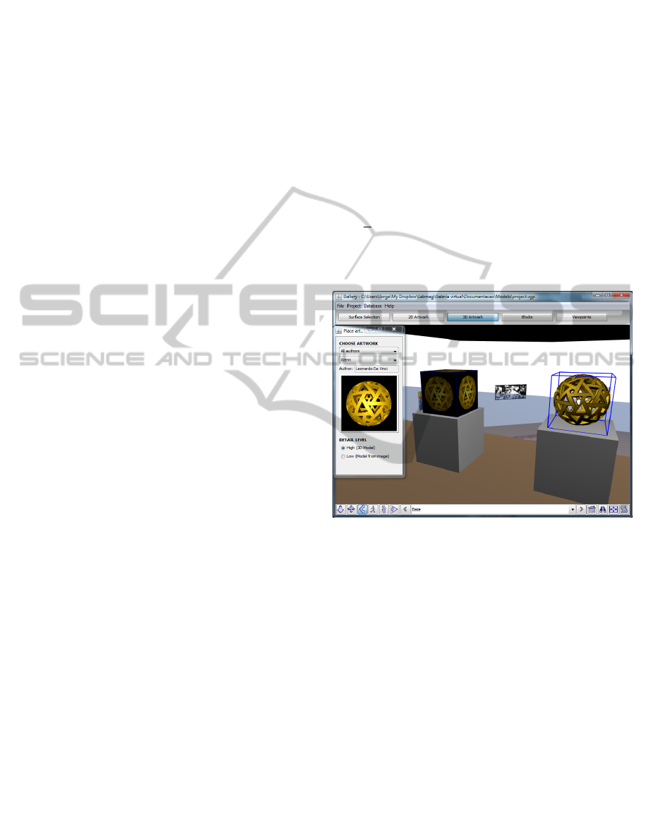
3D artworks are stored as X3D models. A
simplified representation can be built based on the
physical dimensions and a single image of the
artwork. In this case, a parallelepiped is placed in the
scene
and the image of the object is applied as
texture to all faces. In Fig. 1 there is an example of
two different representations of the same 3D
artwork.
Figure 1: Two alternative representations of the same
artwork are shown.
In addition to artworks, it is also possible to add
removable structures, like dividing walls or plinths.
For this purpose the user can place in the scene
parallelepiped objects, choosing their size and
colour. Once placed in the scene, the areas that
compose the surfaces are also considered suitable for
the placement of artworks and can be chosen in
surface selection edit mode.
Viewpoints. X3D allows the definition of pre-
defined positions for the user, called viewpoints,
which are associated with a direction of sight. To
support viewpoint definition interactively, the
application is capable of automatically obtaining the
position from where the user is looking at the scene
and allows the user to define that view as a
viewpoint.
X3D Exhibition File Generation. The X3D file
containing the description of the virtual exhibition is
produced through a process where each edit mode
GRAPP 2011 - International Conference on Computer Graphics Theory and Applications
332
independently writes its changes to the output file.
The file containing the original scene graph is
modified using the DOM (Document Object Model)
interface provided by Java API for XML processing.
Note that the changes made to the original file are
mostly addition of new nodes, not modification of
existing ones.
Exhibition Re-edition. To make adjustments to a
virtual exhibition previously built, the X3D file
resulting from its construction does not have all the
required information. Hence it is necessary to know
which objects were introduced in the initial scene.
To enable the re-editing of virtual exhibitions, a
mechanism was designed based on a set of auxiliary
data structures that store information about all
objects added to the scene. The contents of these
structures can be saved in a file - called the state file
- which reflects the current editing state of a scene.
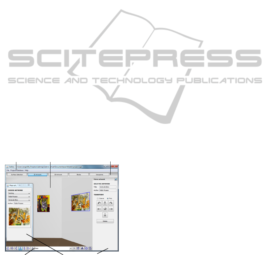
3.3 User Interface
The user interface is composed of two sets of
elements: one is shared by all edit modes while the
other depends on the active edit mode.
The shared elements are split into three different
zones (Fig. 2): (1) the menu bar, with common
options like file save and file load; (2) the edit mode
switch buttons and (3) the 3D browser, including the
display area and the navigation bar.
The edit mode dependent options (4) are
displayed in two lateral panels, which can be
detached from the main window, as shown in Fig. 2,
or hidden in order to maximize the 3D display area.
Figure 2: User interface for 2D object placement.
The added objects in the 3D scene are
highlighted using coloured bounding boxes whose
visual appearance indicates if they belong to the
active edit mode, if they are selected or if the cursor
is over them, as shown in Fig. 1. The selectable
surfaces also display similar behaviour, but using
colour overlays to achieve the different appearances.
4 CONCLUSIONS AND FUTURE
WORK
We have presented an interactive tool - Virtual
Exhibition Builder - for building virtual exhibitions.
This tool aims to assist museum teams in the initial
stages of mounting an exhibition. In addition, the
resulting virtual exhibition can be shown through the
Web for diffusion purposes.
The development of this tool received input from
the experience gained in a previous work and was
designed in order to overcome its limitations. This
tool was presented to specialists from a museum and
several improvements were introduced afterwards.
Future developments include the creation of
printed layouts of the surfaces, with artworks
annotated with the distances between them and the
floor; the ability to change the colour of the
exhibition surfaces; the projection of videos on
surfaces; the reproduction of music depending on the
site that is being viewed at the time; the capability of
displaying in the scene details from the selected
artworks, such as title and author, in order to provide
more information to visitors at the virtual exhibition.
ACKNOWLEDGEMENTS
We would like to thank to Foundation Amadeu Dias
(University of Lisbon) and to Dr. Ana Cristina Leite
and her team.
REFERENCES
Gomes, J. C., Carmo, M. B., Cláudio, A. P. 2010.
Construção Interactiva de Exposições Virtuais.
INFORUM 2010, in Portuguese
Hrk, S. 2001. Virtual Art Gallery. CESCG 2001.
Katalabs, http://www.katalabs.com/blog/
Semião, P. M., Carmo, M. B. 2008. Virtual Art Gallery
Tool. GRAPP 2008, pp 471-476
Web 3D, http://www.web3d.org/
Wojciechowski, R., Walczack, K, White, M., Cellary, W.
2004. Building Virtual and Augmented Reality
Museum Exhibitions. 3D Web Technology 2004, pp
135-144
(4)Edit mode specific options
(1)Menu bar
(3)Display area
(3)Navigation bar
(2)Edit mode switch buttons
VIRTUAL EXHIBITION BUILDER
333
