
LARGE SCALE LOCALIZATION
For Mobile Outdoor Augmented Reality Applications
I. M. Zendjebil, F. Ababsa, J-Y. Didier and M. Mallem
IBISC Laboratory, University of Evry Val d’Essonnes, Evry, France
Keywords:
3D localization, Outdoor application, Hybrid sensor, Fallback system, Markerless pose estimation, 2D/3D
matching.
Abstract:
In this paper, we present an original localization system for large scale outdoor environments which uses a
markerless vision-based approach to estimate the camera pose. It relies on natural feature points extracted from
images. Since this type of method is sensitive to brightness changes, occlusions and sudden motions which
are likely to occur in outdoor environment, we use two more sensors to assist the vision process. In our work,
we would like to demonstrate the feasibility of an assistance scheme in large scale outdoor environment. The
intent is to provide a fallback system for the vision in case of failure as well as to reinitialize the vision system
when needed. The complete localization system aims to be autonomous and adaptable to different situations.
We present here an overview of our system, its performance and some results obtained from experiments
performed in an outdoor environment under real conditions.
1 INTRODUCTION
Localization process is crucial for many applications
such as augmented reality or robotics. Most systems,
mainly those based on video see-through, use vision-
based approaches. The vision-based approaches esti-
mate the camera pose. However, in outdoor environ-
ments, these approaches are sensitive to work condi-
tions such as brightness changes, occlusions and sud-
den motions. For this reason, these applications con-
verge to use hybrid sensor systems to overcome the
drawbacks of using a single type of sensor (i.e. cam-
era) in order to gain in robustness and accuracy.
The idea of combining several kind of sensors is
not new. Indeed, in (Azuma, 1993), following the reg-
istration criteria imposed by the AR applications, R.
Azuma suggests to use the hybrid sensors in order to
improve efficiency. He gives the example of inertial
sensors which have infinite range but poor accuracy
due to accumulated drift. Using specific measure-
ments provided by several types of sensors during a
short time can correct the drift and improve the ef-
ficiency of each used sensor. In parallel, in robotic
applications, Vi
´
eville et al. (Vi
´
eville et al., 1993) pro-
posed to cooperate the vision with inertial sensor to
automatically correct the path of an autonomous mo-
bile robot. This idea was inspired by human behavior.
Indeed, the human is moving in its environment using
the vestibular organ, located at the inner ear, and eyes.
By comparison, the inertial sensor has the function of
the vestibular organ and the camera replaces the eye.
In our work, we focus on combining several types
of sensors in order to continuously provide an accu-
rate estimation of the position and the orientation of
the camera assisted by a GPS receiver and an inertial
sensor. These sensors operate following an assistance
strategy where some sensors are used as a fallback to
the other ones. The system adapts to external condi-
tions by changing its internal state.
The paper is structured as follows: After expos-
ing the related works, we present an overview of our
proposed system. The section 3 illustrate a presenta-
tion of the assistance strategy. The section 4 and 5
present the vision-based localization and the predic-
tion and correction process. Experiments and resultas
are developed in the last section.
2 RELATED WORKS
Most works converge towards coupling vision based-
methods and other types of sensors mainly inertial
sensors. We can distinguish between two strategies
for combination: data fusion or assistance.
The data fusion approach aims to merging all data
provided by all sensors (mostly camera and inertial
sensor). Such strategy usually implemats a Kalman
492
M. Zendjebil I., Ababsa F., Didier J. and Mallem M..
LARGE SCALE LOCALIZATION - For Mobile Outdoor Augmented Reality Applications.
DOI: 10.5220/0003364404920501
In Proceedings of the International Conference on Computer Vision Theory and Applications (VISAPP-2011), pages 492-501
ISBN: 978-989-8425-47-8
Copyright
c
2011 SCITEPRESS (Science and Technology Publications, Lda.)

filter (You et al., 1999; Ribo et al., 2002; Hol et al.,
2006; Reitmayr and Drummond, 2006; Bleser, 2009;
Ababsa, 2009; Schall et al., 2009) or a particle fil-
ter (Ababsa and Mallem, 2007; Bleser and Strickery,
2008) in order merge data. Generally, data from other
sensors such as gyroscopes and magnetometers are
used to predict the 3D motion of the camera which is
then refined using artificial vision techniques. These
approaches are interesting because the measures are
estimated by combining all data from various sensors
used on a model that describes the cinematic camera
motion. Some works propose to use complementary
type filter such as in (Ababsa and Mallem, 2007) to
compensate the differences in sampling time and the
unavailability of data at certain times.
Other works proposed to use an assistance
scheme. The principle is to rely on a main sensor to
provide accurate and robust localization and replace
it by others sensors when it fails to provide a con-
sistent measure. This concept appears with the work
of Borenstein and Feng (Borenstein and Feng, 1996)
in order to combinate gyros and odometry in mobile
robots. The development of this approach aims to
overcome the fact that using motion models do not
anticipate a kinf of motion. Vision has demonstrated
through several works that it is able to provide satis-
factory camera pose estimation. However, the prob-
lem arises when the sensor is unable to provide a con-
sistent estimate in case of occlusions (partial or total)
or sudden motion that may occur in hand-held sys-
tems. In these cases, vision needs to be substitued
by other sensors. So, an assistance strategy relies on
two subsystems: a main subsystem and an fallback
subsystem. The main subsystem provides continu-
ous measurements. When it fails, the fallback subsys-
tem takes over until the main subsystem is operational
again. We find this principle in Aron et al (Aron et al.,
2007) and Maidi et al. (Maidi et al., 2005) works.
Following an assistance scheme, our idea is to pro-
pose an autonomous system that adapts to different
situations encountered while working. According to
available data, the system decides to perform a partic-
ular type of processing in order to continuously pro-
vide an accurate localization estimation. This is re-
flected when the vision defined as main subsystem is
operational, the localization system grants its confi-
dence in measures provided by vision-based methods.
The system should be able to detect the vision failure
in order to switch to the assistance system. Certainly
the idea of the assistance is not new. However, it has
only been tested in small indoor environments. Our
goal is to see the behavior of such strategy in large
scale environments and see its potential outdoor and
in mobile situation. We aim at proposing a palliative
method to vision. We want to propose a software so-
lution which gives some intelligence to the system so
it can adapt itself according to available data and the
tracking accuracy.
3 SYSTEM OVERVIEW
In our work, we are moving to a system combining
several types of sensors. Our hardware system is
composed of a tablet-PC connected to three sensors
dedicated to the localization task (cf. fig.1): a GPS
receiver worn by the user and an inertial sensor at-
tached rigidly to a camera. The GPS returns a global
positioning. The inertial sensor estimates 3D orien-
tations, accelerations, angular velocity and 3D mag-
netic fields. The camera is used for the visual feed-
back and to exploit video stream to provide camera
pose. The combination of the GPS receiver and the in-
ertial sensor can provide an estimation of the position
and orientation. Thus, using an assistance scheme,
our system will be divided in two subsystems: a main
vision subsystem and a fallback subsystem using GPS
and inertial data called Aid-Localization (AL) subsys-
tem (Zendjebil et al., 2008). The AL subsystem is not
only restricted to the fallback functionnality. It has
a hand in the process of (re)initialization of the main
subsystem.
(a) Tablet PC with Camera and
inertial sensor
(b) GPS receiver
Figure 1: Hardware platform.
Several issues must be taken into account to im-
plement this system. Among them, the hybrid sensor
should be calibrated in order to define the relation-
ship between the different sensors local coordinate
system and standardize measurements in the same co-
ordinate system. We use calibration process described
in (Zendjebil et al., 2010). Another problem is to de-
fine criteria to detect failures of the vision subsystem.
Added to this is the imprecision of measurements pro-
vided by the assistance subsystem compared to vi-
sion. Therefore, we need to estimate the generated
errors to correct the data in order to converge to the
measurements given by the vision subsystem in terms
of registration accuracy. This brings us to estimate
the offset between the two measurements. So we in-
LARGE SCALE LOCALIZATION - For Mobile Outdoor Augmented Reality Applications
493
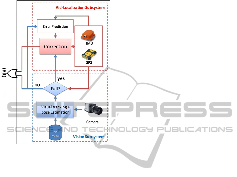
Figure 2: System workflow.
corporate into the aid-localization subsystem a pre-
diction/correction module. Our system is presented
in the figure 2. Our two subsystems are designed to
interact with each other in order to exploit the data
provided by each subsystem. Now we will expose the
details of our assistance strategy.
4 ASSISTANCE STRATEGY
Our system follows on assistance sheme. Thus, we
will decompose it into four states:
1. init state: the system initializes itself using the
semi-automatic approach described in section 5.1;
2. vision predominance state: where the system uses
vision based method for localization;
3. AL predominance state: where the system uses
AL subsystem to estimate the localization;
4. reinit state: through this state, the system tries to
reinitialize the vision after its failure.
The system switches from one state to another ac-
cording to different criteria. To modelize these transi-
tions, we use the formalism of finite state machine
which is a theoretical model composed of a finite
number of states and transitions between these states.
This formalism is mainly used in the theory of com-
putability and formal languages. Using the states pre-
sented above, the transitions described in figure 3 al-
low to control our system as follows:
1. Initially, the system is in the init state where it tries
to perfom 2D/3D matching using semi-automatic
approach (cf. section(5.1));
2. Once the initialization is performed and validated,
the vision subsystem starts. Thus, the system
switches from init state to vision predominance
state (transition (1));
3. When the system is in the predominance Vision
state, it uses the vision-based method described in
5. Each estimated pose is assessed by the system.
If it is validated, it will be used for registration.
Moreover, this pose is used in the learning phase
of the error in the Gaussian process (cf. section
6);
4. If the pose is not validated, the system switches
from predominance vision to the AL predomi-
nance (transition (2));
5. When the tracking system switches to AL predom-
inance, the camera pose is provided by the AL
subsystem using a prediction/correction scheme;
6. After a few video frames, the system tries to reini-
tialize the vision subsystem. Thus, the system
switches to reinit state (transition (3));
7. In reinit state, the system uses an automatic pro-
cedure to find the 2D/3D matches. To speed up
computations, the poses provided by the AL sys-
tem are used to define a search area in the current
image. These search areas are determined around
the projected 3D points with the last pose pro-
vided by the AL subsystem in order to restrict the
area to match patches composed of SURF features
and associated to each 3D point (see section 5.3);
8. If the reinitialization step succeeds, the system
switches to the vision predominance state (tran-
sition (4));
9. If the system does not succeed in reinitializing
the vision subsystem, the system returns to init
state in order to use the semi-automatic procedure
(transition (5));
10. The system offers the possibility for the user to
force the system to switch to init state at any time
if he considers itself the system does not operate
properly (transitions (6) and (7))
VISAPP 2011 - International Conference on Computer Vision Theory and Applications
494
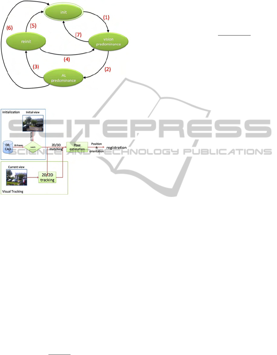
Figure 3: Localization system: state machine.
Figure 4: Point-based method: data flow.
5 VISION-BASED
LOCALIZATION
The vision-based methods use the video stream to es-
timate the camera pose which is the relationship that
maps the world coordinate system R
W
on the cam-
era coordinate systemR
C
. The image is then obtained
by the perspective projection model. Let be M
i
=
(X
i
, Y
i
, Z
i
)
T
, i = 1..n, n ≥ 3 a set of points defined in
R
W
, which coordinates in R
C
, M
c
i
= (X
c
i
, Y
c
i
, Z
c
i
)
T
, are
given by:
M
c
i
= R
CW
M
i
+t
CW
(1)
Such that R
CW
= (r
T
1
, r
T
2
, r
T
3
) and t
CW
= (t
x
, t
y
, t
z
)
T
are
respectively the rotation matrix and translation vector.
If m
i
= (u
i
, v
i
) is the projection image of the point M
i
on a normalized plan, the relationship between M
i
and
m
i
is given by:
m
i
=
1
r
T
3
M
i
+t
z
(RM
i
+t) (2)
This equation is known as collinearity equation. Fi-
nally, the pose estimation is viewed as a minimization
of the error between the 2D image points m
i
and the
projection of 3D points M
i
their corresponding. This
forms a set of 2D/3D matches. The re-projection error
is as follows:
E(R
CW
, t
CW
) =
∑
i
km
i
−
R
CW
M
i
+t
CW
r
T
3
M
i
+t
z
k
2
(3)
There are several algorithms to minimize the criterion
of equation 3. We choose the orthogonal iteration al-
gorithm (IO) (Lu et al., 2000) for its accuracy and
global fast convergence. Thus, to estimate the cam-
era pose using the points, we must find the 2D/3D
matching points. So, we propose a 2D/3D match-
ing point method. The idea is to match the 3D points
considered relevant in a 3D model and can be easily
identified in the images as the corners. However, this
matching step will occur only during an initialization
step and must be maintained in the video stream in or-
der to be able to estimate the pose. This initialization
phase is followed by a 2D visual tracking. Indeed,
the visual tracking allow us to find the positions of
2D points, originals identified as a projection of 3D
points in each new image of the video stream. By
finding the position of these points in each image, we
can indirectly obtain the 2D/3D matching. Indeed,
knowing the 2D/3D matching at time t, and following
the tracking from points in image t to the image t + 1,
we deduce the 2D/3D matching. The figure below
(see fig.4) illustrates the data flow of the method de-
scribed above. Now we will describe the initialization
method that we propose.
5.1 Semi-automatic Approach
The initialization process is very important. It repre-
sents the process that matches 3D visible points with
their 2D projections in the initial view. A bad match-
ing affects the 3D localization estimation. In order
to avoid a full manually point matching done by the
user, we propose a semi-automatic matching proce-
dure. The approach consists in making a rendering of
a wireframe model that is manually registered by the
user over the real view by moving around the cam-
era. Once the registration is validated, the second step
consists in identifying the 2D correspondances points.
The process detects the corners close to the projec-
tions of the 3D points using Harris detector (Harris,
1993). For each 3D point, we associate a SURF de-
scriptor (Bay et al., 2008). Next, the process matches
a 2D points which have the shortest distance between
its descriptor and the descriptors computed off-line to
the 3D points of the model. Once the 2D/3D match-
ing is obtained, the second phase is to maintain it
throughout the video stream by track visually the ob-
tained 2D points using Kanade-Lucas-Tomasi Tracker
LARGE SCALE LOCALIZATION - For Mobile Outdoor Augmented Reality Applications
495

(KLT) (Lucas and Kanade, 1981). This method has
the advantage of operating in real time.
5.2 Failure Tests
The pose estimated by vision can be wrong. So, we
need to handle errors in order to switch to the Aid-
Localization subsystem. The errors are due to sev-
eral parameters affecting the visual tracking mainly
occlusions, sudden motion and the change of bright-
ness. Therefore, we define some criteria for judging
the validity of the estimated pose. If one of these cri-
teria is not verified, the pose is rejected and the system
switches to the Aid-Localization subsystem.
5.2.1 Number of Tracked Points
The number of 2D/3D matching points affects the ac-
curacy of the minimization of the equation 3. Indeed,
the more we have 2D/3D matched points; the more
the estimated pose is accurate. We empirically de-
fined a minimum number of matching. Below this
threshold, it is considered impossible to estimate the
pose with the vision. Theoretically, we need 3 points
to estimate the camera pose but in practice with 10
points, well distributed in the scene, we obtain a good
estimation.
5.2.2 Projection Error
The number of matched points is not sufficient, we
use also projection error. This error represents the av-
erage square of the difference between the projection
of 3D points using estimated pose and the 2D image
points. If the error is large (greater than an thresh-
old), the pose is considered wrong. The reprojection
threshold is defined in the range of 25 to 100 pixels
2
.
5.2.3 Confidence Intervals
In addition to the above criteria, the data provided by
the Aid-localization subsystem can be used as an in-
dicator of validity for the camera poses obtained by
the vision subsystem. Indeed, these data can be used
to define confidence intervals, for judging whether
the camera pose is consistent or not. Thus, from
each position obtained from GPS and transformed
with the calibration parameters, we can define an el-
lipse whose center is determined by this position and
whose axes are defined by 3σ (the standard devia-
tion of the offset obtained between GPS and cam-
era position) or empirically. During the validation
step, the position obtained with the camera is checked
against the obtained confidence interval. If this posi-
tion is defined in this interval, it is considered valid
otherwise it is rejected. Regarding orientation, each
orientation given by the camera is compared to the
orientation given by the inertial sensor. The sys-
tem estimate the difference between the two rotations
(∆R = R
T
CW
f (R
GI
)). Computing the trace of this dif-
ference, we can deduce the angle θ between these two
rotations as θ = arccos
Trace(∆R)−1
2
. If both rotations
are identical, the result should be equal to the identity
matrix which trace is equal to 3 (i.e. θ = 0). Thus,
the validity test consists in estimating the trace of the
difference of the two rotations. Then, if this trace is
below a defined threshold, the obtained orientation is
considered valid otherwise it is rejected. In practise,
we choose threshold equal to 2.9 which corresponds
to ≈ 18
◦
5.3 Automatic Initialization
Unlike the semi-automatic approach, the automatic
approach does not need the intervention of the user.
This approach is useful to reinitialize the vision sub-
system. The idea consists in using the patches. But
instead of associating for each 3D point an image ar-
eas centered around this point, we will use descrip-
tors extracted around each 2D projection of a 3D point
model by defining an area centered around this point,
using an operator to detect features points. We use
the SURF detector. This detector is characterized
by its robustness and its invariance against rotation
and scale changes. The SURF points defined around
the projection of 3D points can recover indirectly the
matching of the 3D points. To find the corresponding
of the projections of 3D points, we choose to find the
relationship between two images. Identifies the trans-
formation that maps a point m
i
defined in image i to
image j at the point m
j
. This homography is calcu-
lated from a set of matches, in our case obtained from
SURF matching. This homography can find the corre-
sponding 3D points by transforming their 2D projec-
tions in image i to the image j using the estimated ho-
mography. In this way, if we know the 2D/3D match-
ing at time i, we can find them at time j. To make
the matching robust and eliminate outliers, we use the
RANSAC algorithm (Fischler and Bolles, 1981).
6 ERROR PREDICTION
AND CORRECTION
The estimation of the produced error is important in
our localization process. Indeed, it allows quantify-
ing the quality of measurements in order to improve
the 3D localization estimation provided by the AL
VISAPP 2011 - International Conference on Computer Vision Theory and Applications
496

subsystem. Our error represents the offset between
the camera pose and the position and orientation de-
duced from GPS and inertial sensor. When the vi-
sion fails, we need to predict this error. So, we model
this error as a regression with a Gaussian process
(Williams, 1997). The idea of using the Gaussian pro-
cess to predict error has been proposed in the work of
Drummond and Reitmayr (Reitmayr and Drummond,
2007). They used to predict the error of GPS in order
to reinitialize the visual tracking. During visual track-
ing, we record the offset between the AL subsystem
and vision subsystem. This represents an online train-
ing step. When the visual tracking fails, the Gaussian
process predicts the offset made by GPS. This offset
which is represented by the mean error is used to cor-
rect the estimation of 3D localization.
7 EXPERIMENTS AND RESULTS
Our system is developed using ARCS (Didier et al.,
2006) (Augmented Reality System Component), a
component-programming system. ARCS allows to
prototype rapidly AR applications and facilitates in-
terfacing multiple heterogeneous technologies. On
the one hand, ARCS uses a programming paradigm
of classical components specially designed to meet
the constraints imposed by the AR applications (es-
pecially real-time constraint). On the other hand,
ARCS is based on a finite state machine which allows
switching from one state to another state resulting in
the reconfiguration of the organisation of our compo-
nents. This feature facilitates the implementation of
our hybrid system.
The experiments were performed using an USB uEye
UI-2220RE industrial camera with 8mm focal length.
The camera captures a video frames with a resolution
of 768x576. Our tests are performed at 10 fps. The
attached inertial sensor is an XSens MTi which con-
tains gyroscopes, accelerometers and magnetometers
and provides 3D orientation data. The GPS receiver is
a Trimble Pro XT which has an accuracy lower than
the meter. The system runs on a handheld Dell tablet-
PC Latitude XT CORE 2 DUO U7700(1, 33GHZ)A.
For all our experiments, we have a 3D model of the
building we track in the scene. This model is build
based on data acquired using telemetry and building
blueprints. The model contains primarily a set of rel-
evant 3D points of the building.
We evaluated our localization system using real data
acquired in outdoor under real conditions. The cam-
era was calibrated off-line using the Faugeras-Toscani
algorithm (Faugeras and Toscani, 1987) to compute
intrinsic parameters. The hybrid sensor was cali-
brated using a set of reference data (GPS positions
and images for GPS/Camera calibration and inertial
sensor orientations and images for Inertial/Camera
calibration). The experiments conducted are intended
to demonstrate how the system operates in different
situations, mainly:
1. The occlusion of tracked points: this may be
caused by objects or by the camera motion;
2. The brightness variations;
3. Sudden and rapid motion of camera worn by the
user.
The system is worn by a un constrained user moving
in an outdoor environment. In parallel, the system
estimates the position and orientation of the camera.
In order to visualise the obtained results, we will
register a wireframe model representing the envi-
ronment. We opt for a color code to differentiate
between the two sub-systems operational. Thus, if
registration is obtained with data provided by the
vision subsystem, the model will be shown in red.
Otherwise if the poses are calculated with the AL
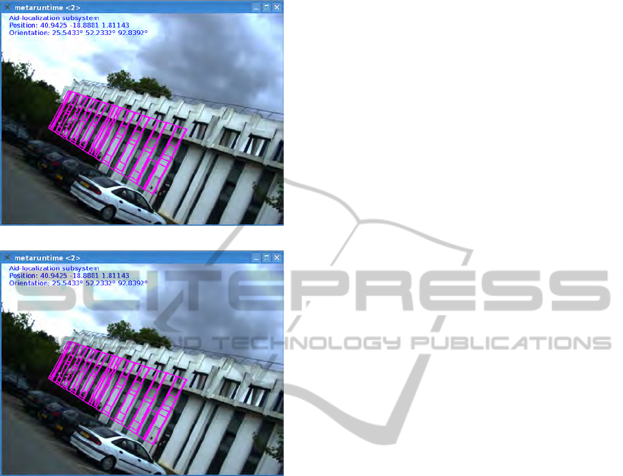
subsystem, the model is in magenta.
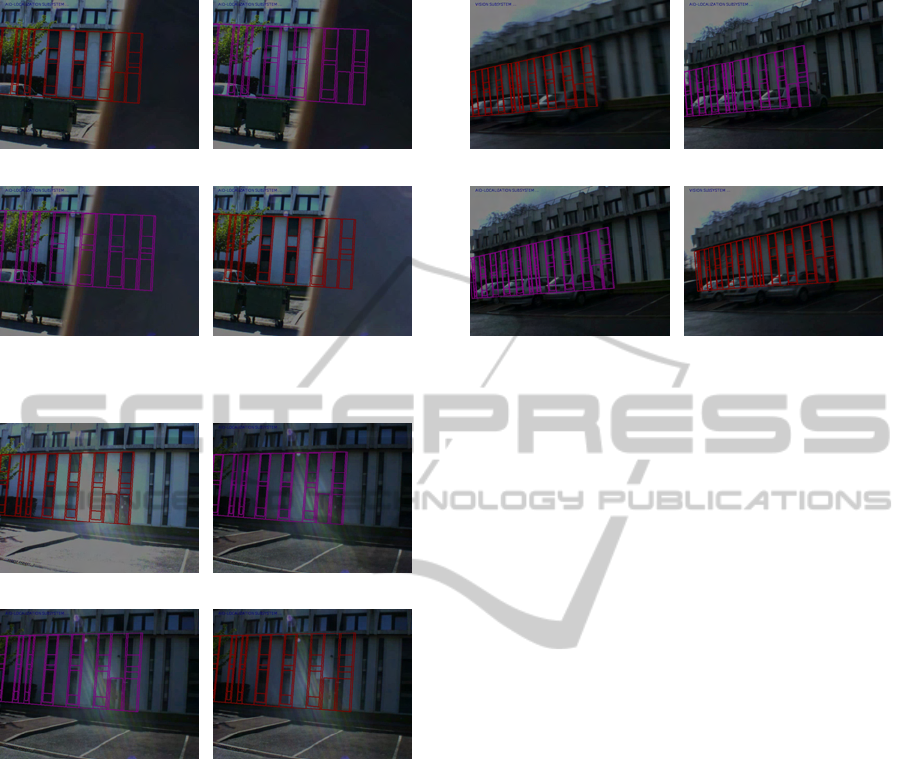
7.1 Occlusion Case
When the vision subsystem was in operation, we have
obscured some of the tracked points used in the pose
estimation. We can see in figure 5 an example of
obtained results. We can observe that in 5-(b-c) the
system uses the Al subsystem to align the wireframe
model on real image. The localization system detects
that there are not enough points to estimate the pose
using the vision. Thus, the system switches to the AL
subsystem that provides the necessary poses for regis-
tration. Meanwhile, the localization system is trying
to reinitialize the vision. When it succeeds to obtain a
sufficient number of matching points, the vision sub-
system reprises his role as can be noted from Figure
5-d. We conducted these tests several times and in
each time the system can adapt to the situation. Con-
cerning the registration when the system uses the AL
subsystem, we can see that the wireframe model is
registered properly on the real view. Admittedly, this
registration is not accurate compared to what gives
the vision, but this is enough. In addition, projections
of 3D points are in the neighbourhood of their corre-
spondent, which helps in the reintialisation step.
7.2 Case of Change in Brightness
The variations in brightness affect directly the visual
tracking and can generate false matches. Figure 6
LARGE SCALE LOCALIZATION - For Mobile Outdoor Augmented Reality Applications
497
(a) (b)
(c) (d)
Figure 5: Semi-occlusion case: Obtained results.
(a) (b)
(c) (d)
Figure 6: Change in brightness are handled properly.
shows an example of variation in brightness which
we can see that the image becomes darker (see fig.
6-b and 6-c ). When the brightness varies the visual
tracking fails. The AL subsystem replaces it. We can
observe that the reinitialization approach has find suc-
cessfully the 2D/3D matching despite the difference
in brightness. This is due to the use of SURF descrip-
tors which have the advantage of being invariant to
changes in brightness.
7.2.1 Sudden Motion Case
In mobile situation, the user’s motion are not always
smooth, uniform and slow. Indeed, they may be
abrupt and thus create blurred images. In this case,
the visual tracking fails. In fast motion case, the im-
age displacement can be important and thus the visual
tracking can not find any matches or tends to cause
(a) (b)
(c) (d)
Figure 7: Sudden motion case: obtained results.
mismatches. We have in figure 7-b an example of
blurred image due to a rapid motion of the camera
caused by user mobility.
The presence of the blur is detected by an insufficient
number of point or a high projection error. The AL
subsystem becomes functional until the vision sub-
system reinitializes (see fig. 7-d) . However, we
found that in some cases from the registration ob-
tained with AL subsystem data is not good enough.
This is because sometimes in the presence of sud-
den motion, the failure of the visual tracking is not
detected quickly which influences the measurements
used for the correction.
7.3 System in Mobility Situation
The results obtained when the whole system is func-
tional is given below. The initialization process al-
lows us to have the matching of the 3D visible points
from the 3D model with their projections in the first
view. From this 2D/3D matching, the set of 2D points
are tracked from one frame to another. For each
frame, we register the wireframe model using the po-
sitions and orientations obtained with our hybrid lo-
calization system.
In figure 8, the green color projection is obtained
from the positions and orientations provided by the
vision subsystem. Visually, the model is registered to
the real view. In magenta, the projected model is ob-
tained with the positions and orientations provided by
the Aid-Localization subsystem. We observe on fig-
ure 8 that when vision fails, the localization system
switches to the Aid-localization subsystem to provide
localization. The localization is corrected with the
predicted error which contributes to improve the es-
timation (Figure 8). The obtained results are quite
VISAPP 2011 - International Conference on Computer Vision Theory and Applications
498
(a) #0686 (b) #1053
(c) #1054 (d) #1055
Figure 8: Registration of the 3D model using the poses ob-
tained with our Hybrid system.
(a) #1236 (b) #1239
(c) #1245 (d) #1269
Figure 9: Registration of the 3D model using the Aid-
Localization subsystem: Occlusion case.
satisfactory regarding our needs (i.e. correct registra-
tion).
In figure 9, we can observe that during the occlusion
of tracked points the Aid-localization subsystem al-
lows to provide an estimation of the position and ori-
entation. Therefore, even in total occlusion, our sys-
tem can provide a rough estimation of the localiza-
tion.
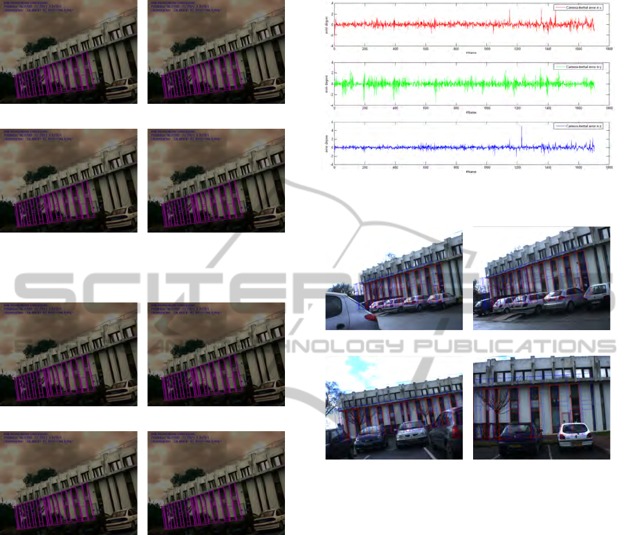
7.4 Performances of System
To assess the accuracy of the inertial sensor, we com-
pared the orientations produced from the sensor data
to those computed by the vision pose estimation al-
gorithm. We recorded a video with several orienta-
tions in an outdoor environment. The two sensors are
Figure 10: Angle errors = Camera’s orientation vs. Inertial
sensor’s orientation.
(a) (b)
(c) (d)
Figure 11: Registration using vision subsystem (red line)
vs. AL subsystem without correction (bleu line).
also time-stamped. Figure 10 shows the error between
the two orientations. With a mean error of about
(θ
x
= 0.27
◦
, θ
y
= 0.41
◦
, θ
z
= 0.24
◦
) and standard de-
viations of (0.28, 0.43, 0.25), we obtained good re-
sults. These errors which are acceptable (in some ex-
treme cases around 5
◦
) can be caught and corrected
with the error prediction.
Regarding the realignment, we present in figure
11 a comparaison between the results obtained with
the vision subsystem and AL-subsystem. The pro-
jected model shown in red line is obtained with the
poses estimated using the vision. We obtain a mean
reprojection error around 1.67 pixels with a standard
deviation about 2.37. Furthermore, with the AL sub-
system, we obtain the model proposed in blue. From
the poses provided by the AL subsystem, the system
gives a mean reprojection error equal to 47 pixels with
a standard deviation of 60. Note that this result is ob-
tained without correction. However, in our various
tests, we found out that external factors can affect the
inertial measurements, particularly in defining its lo-
LARGE SCALE LOCALIZATION - For Mobile Outdoor Augmented Reality Applications
499
(a) Without correction
(b) With correction
Figure 12: Registration using inertial sensor’s orientaion
and GPS position.
cal level reference frame R
G
where the x axis points
local magnetic north. This causes errors in the orien-
tations’ estimation. To correct this, we propose to re-
estimate continuously the rotation between R
G
asso-
ciated and the world reference frame R
W
. By observ-
ing the registration of the wireframe model on the real
image, drift can be observed in figure 12. Figure 12.a
present the registration using orientation provided by
the inertial sensor and without correcting the rotation.
We notice clearly that the wireframe is not aligned
correctly due to wrong orientation contrary to figure
12.b where the rotation R
GW
is corrected online, the
wireframe is registered correctly over the real view.
8 CONCLUSIONS
AND FUTURE WORK
In this paper, we have presented a localization system
combining three sensors (camera, GPS and inertial
sensor) dedicated to large scale outdoor environ-
ments. The proposed system operates under an as-
sistance scheme by defining two subsystems. The
main subsystem is represented by vision that provided
continuously localization measurements using mark-
erless approch. The fallback subsystem, called Aid-
Localization, is composed of the GPS receiver and the
inertial sensor. This subsystems has the main role to
replace the vision subsystem where it can not provide
a correct localization measurements. In deed, accord-
ing to the extern conditions, the system changes its
internal state to adapt itself and to provide a local-
ization measurement under any circumstance. These
state changes trigger switches from a subsystem to an-
other according to available data and localization ac-
curacy.
Various issues were addressed. In addition to
calibration approaches, we are interested primarily
in how to handle the different switches and to pro-
pose appropriate approaches. The vision subsystem
used a point-based pose estimation approach which
used a natural 2D points extracted from images and
matched to a 3D model that describes the 3D structure
of the environment. So, we have proposed two effi-
cient initialization approaches (a semi-automatic and
automatic) which allows to match 2D image points
with 3D points. The automatic approach allows to
reinitialize the vision subsystem by using descriptors
patches. The method is efficient, robust and accurate
even when the point of views are very different (large
motion and/or brightness variations ). To improve
the accuracy of the AL subsystem, we use Gaussian
process to predict and correct the error introduced by
GPS and inertial sensor in order to have the same ac-
curacy in registration as vision subsystem.
We can conclude that the obtained results are quite
satisfactory with respect to the purpose of an AR sys-
tem (i.e. correct registration) with a quite good ac-
curacy. Tested in outdoor environment, our system
adapts to the conditions in the environment. For ex-
ample, as shown in the results, in the case of total oc-
clusion, the AL system takes over the 3D localization
estimation until the vision becomes operational.
However, improvements must be made in vision-
based method. Indeed, other vision-based methods
can be used such as edge-based methods to improve
the accuracy of the vision-based pose estimation. In
addition, to provide more mobility to the user, the sys-
tem can contain a SLAM (Simultaneous Localization
and Mapping) approach in order to reconstruct un-
modelled environment. This allows to enrich online
the 3D model and also allow to the user to evolve in
this part.
VISAPP 2011 - International Conference on Computer Vision Theory and Applications
500

ACKNOWLEDGEMENTS
This work is supported by the RAXENV project
funded by the French National Research Agency
”ANR”.
REFERENCES
Ababsa, F. (2009). Advanced 3d localization by fusing
measurements from gps, inertial and vision sensors.
In Systems, Man and Cybernetics, 2009. SMC 2009.
IEEE International Conference on, pages 871 –875.
Ababsa, F. and Mallem, M. (2007). Hybrid 3d camera
pose estimation using particle filter sensor fusion. In
Advanced Robotics, the International Journal of the
Robotics Society of Japan (RSJ), pages 165–181.
Aron, M., Simon, G., and Berger, M. (2007). Use of inertial
sensors to support video tracking: Research articles.
Comput. Animat. Virtual Worlds, 18(1):57–68.
Azuma, R. (1993). Tracking requirements for augmented
reality. Commun. ACM, 36(7):50–51.
Bay, H., Ess, A., Tuytelaars, T., and Goo, L. V. (2008). Surf:
Speeded up robust features. Computer Vision and Im-
age Understanding (CVIU), 110(3):346–359.
Bleser, G. (2009). Towards Visual-Inertial SLAM for Mo-
bile Augmented Reality. PhD thesis, Technical Uni-
versity Kaiserslautern.
Bleser, G. and Strickery, D. (2008). Using the marginalised
particle filter for real-time visual-inertial sensor fu-
sion. Mixed and Augmented Reality, IEEE / ACM In-
ternational Symposium on, 0:3–12.
Borenstein, J. and Feng, L. (1996). Gyrodometry: A new
method for combining data from gyros and odom etry
in mobile robots. In In Proceedings of the 1996
IEEE International Conference onRobotics and Au-
tomation, pages 423–428.
Didier, J., Otmane, S., and Mallem, M. (2006). A compo-
nent model for augmented/mixed reality applications
with reconfigurable data-flow. In 8th International
Conference on Virtual Reality (VRIC 2006), pages
243–252, Laval (France).
Faugeras, O. and Toscani, G. (1987). Camera calibration
for 3d computer vision. In Proc. Int’l Workshop In-
dustrial Applications of Machine Vision and Machine
Intelligence, pages 240–247.
Fischler, M. A. and Bolles, R. C. (1981). Random sample
consensus: a paradigm for model fitting with appli-
cations to image analysis and automated cartography.
Commun. ACM, 24(6):381–395.
Harris, C. (1993). Tracking with rigid models. Active vi-
sion, pages 59–73.
Hol, J., Schon, T., Gustafsson, F., and Slycke, P. (2006).
Sensor fusion for augmented reality. In Information
Fusion, 2006 9th International Conference on, pages
1–6, Florence. IEEE.
Lu, C.-P., Hager, G. D., and Mjolsness, E. (2000). Fast
and globally convergent pose estimation from video
images. IEEE Trans. Pattern Anal. Mach. Intell.,
22(6):610–622.
Lucas, B. and Kanade, T. (1981). An iterative image regis-
tration technique with an application to stereo vision.
In IJCAI81, pages 674–679.
Maidi, M., Ababsa, F., and Mallem, M. (2005). Vision-
inertial system calibration for tracking in augmented
reality. In 2nd International Conference on Informat-
ics in Control, Automation and Robotics, pages 156–
162.
Reitmayr, G. and Drummond, T. (2006). Going out: Robust
model-based tracking for outdoor augmented reality.
In IEEE ISMAR, Santa Barbara, California, USA.
Reitmayr, G. and Drummond, T. (2007). Initialisation for
visual tracking in urban environments. In IEEE IS-
MAR, Nara, Japan.
Ribo, M., Lang, P., Ganster, H., Brandner, M., Stock, C.,
and Pinz, A. (2002). Hybrid tracking for outdoor aug-
mented reality applications. IEEE Comput. Graph.
Appl., 22(6):54–63.
Schall, G., Wagner, D., Reitmayr, G., Taichmann, E.,
Wieser, M., Schmalstieg, D., and Wellenhof, B. H.
(2009). Global pose estimation using multi-sensor fu-
sion for outdoor augmented reality. In In Proceedings
of IEEE Int. Symposium on Mixed and Augmented Re-
ality 2009, Orlando, Florida, USA.
Vi
´
eville, T., Romann, F., Hotz, B., Mathieu, H., Buffa, M.,
Robert, L., Facao, P., Faugeras, O., and Audren, J.
(1993). Autonomous navigation of a mobile robot
using inertial and visual cues. In Proceedings of the
IEEE International Conference on Intelligent Robots
and Systems.
Williams, C. (1997). Prediction with gaussian processes:
From linear regression to linear prediction and be-
yond. Technical report, Neural Computing Research
Grou.
You, S., Neumann, U., and Azuma, R. (1999). Orien-
tation tracking for outdoor augmented reality regis-
tration. IEEE Computer Graphics and Applications,
19(6):36–42.
Zendjebil, I., Ababsa, F., Didier, J.-Y., and et M. Mallem
(2010). A gps-imu-camera modelization and calibra-
tion for 3d localization dedicated to outdoor mobile
applications. In International Conference On Control,
Automation and system.
Zendjebil, I. M., Ababsa, F., Didier, J.-Y., and Mallem, M.
(2008). On the hybrid aid-localization for outdoor
augmented reality applications. In VRST ’08: Pro-
ceedings of the 2008 ACM symposium on Virtual re-
ality software and technology, pages 249–250, New
York, NY, USA. ACM.
LARGE SCALE LOCALIZATION - For Mobile Outdoor Augmented Reality Applications
501
