
PLACEMENT OF HARDWARE TASKS ON FPGA
USING THE BEES ALGORITHM
Bassem Ouni, Ikbel Belaid, Fabrice Muller
University of Nice Sophia-Antipolis, LEAT CNRS, 250 rue Albert Einstein, bat 4, 06560 Valbonne, France
Maher Benjemaa
University of Sfax, National School of Engineers of Sfax, Research Unit ReDCAD, BP 1173-3038 Sfax, Tunisia
Keywords:
Reconfigurable zones, Hardware tasks, FPGA, Placement and mapping, Optimization problem, Bees algo-
rithm.
Abstract:
The dynamic and partial reconfiguration in FPGA with heterogeneous resources is a challenge for the next
years. It allows reconfiguring a specific hardware zone in FPGA while maintaining the activity of the remain-
ing circuit’s part. This paper introduces a new approach about how to solve the problem of placement of the
hardware tasks on the recent reconfigurable technology using the honey Bees Algorithm. This approach aims
at performing a good placement by maximizing the efficiency of the used resources and reducing the task’s
reconfiguration overheads. Experimental results show that the proposed method can perform a good place-
ment of hardware tasks on the device by optimizing significantly the parameters of the cost function in terms
of resources and execution time.
1 INTRODUCTION
The reconfigurable hardware technologies are charac-
terized by many heterogeneous resources and multi-
tasking. Hence, managing the hardware tasks and re-
sources is strongly required. The placement of hard-
ware tasks on FPGA consists of two steps: the first
step is the partitioning, which manages the empty
space in the technology and identifies the potential
sites enabling execution of hardware tasks. The sec-
ond step is the fitting, which selects the feasible place-
ment solution.
In (Bazargan et al., 2000), two methods of place-
ment are introduced: the first one called Keeping All
Maximal Empty Rectangles (KAMER) searches all
the Maximal Empty Rectangles (MER) after plac-
ing each task. Bazargan defines the MERs as the
empty rectangles which are not contained in another
empty rectangle and which are not necessarily dis-
joined. The second method denoted Keeping Non-
overlapping Empty Rectangles keeps all the non-
overlapping holes and is evoked after each split or
merge operation.The work in (Ahmadinia et al., 2004)
introduces a new method of on-line placement by
managing the occupied space instead of free space
due to the big size of the empty rectangles and the
hardness of managing the free space.
The authors in (Marconi et al., 2008) extend the
Bazargan’s placement using an Intelligent Merging
(IM) algorithm. IM combines three techniques of
managing free resources: Merging only if Needed,
Partially Merging and Direct Combine. IM acceler-
ates Bazargan’s method by three times and improves
the placement quality by increasing the rate of ac-
cepted tasks.
A new approach of placement is introduced in
(Handa and Vemuri, 2004) : the method of staircase.
It handles the free space during the first step of the
online placement. It tries to improve the KAMER
method especially for tasks rejection.
Dissimilar to the other methods, we proposed in
recent works an approach which takes into account
the hardware tasks heterogeneity and it is applicable
in the high complex applications. This method of off-
line placement classifies the hardware tasks into many
classes based on their resources; these classes are
called RZ types (Reconfigurable Zones). The phys-
ical representations of the RZs are RPBs (Reconfig-
urable Physical Blocs). These RPBs are 2D rectangu-
lar blocs representing the possible physical locations
498
Ouni B., Belaid I., Muller F. and Benjemaa M..
PLACEMENT OF HARDWARE TASKS ON FPGA USING THE BEES ALGORITHM.
DOI: 10.5220/0003361804980505
In Proceedings of the 1st International Conference on Pervasive and Embedded Computing and Communication Systems (PECCS-2011), pages
498-505
ISBN: 978-989-8425-48-5
Copyright
c
2011 SCITEPRESS (Science and Technology Publications, Lda.)
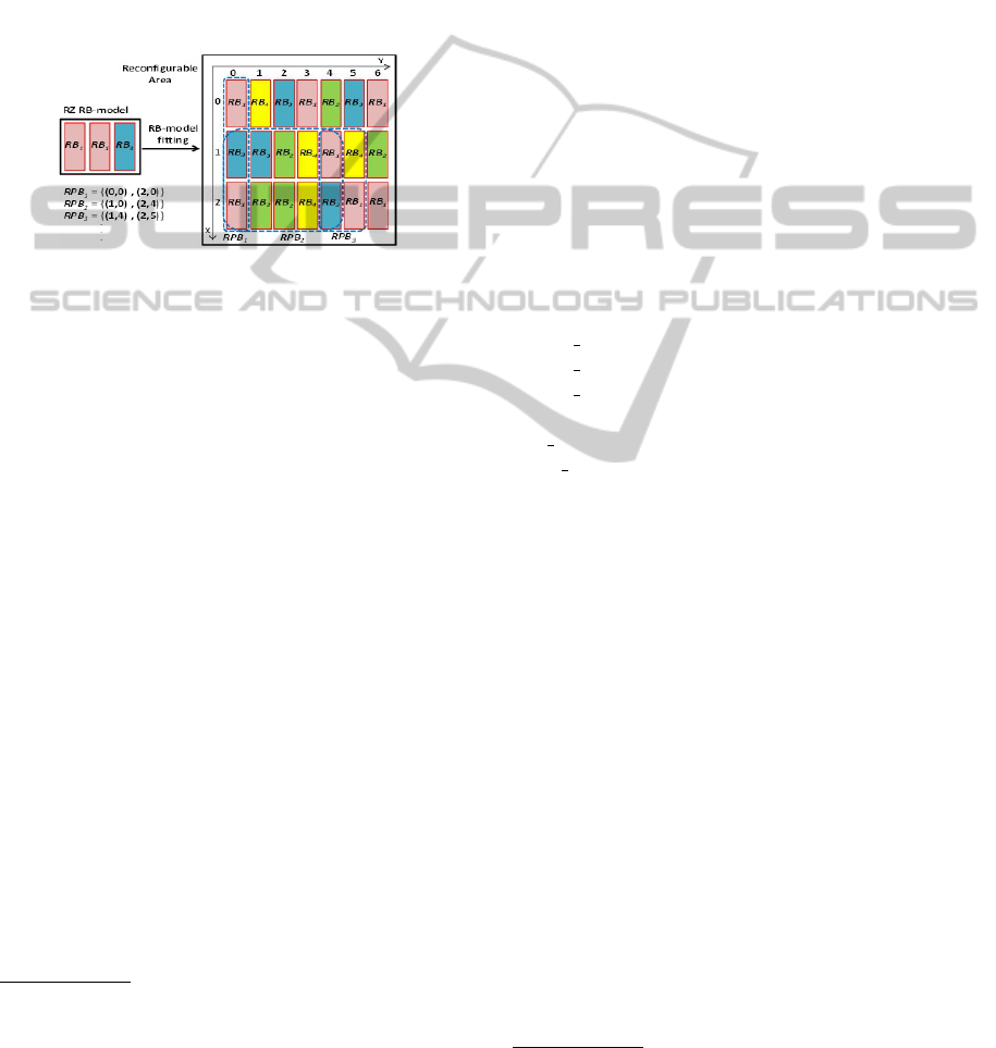
of RZs in the device. As depicted by Figure 1, RZs
and RPBs are modeled by blocs of heterogeneous re-
sources called Reconfigurable Blocs (RB) to obtain
models called RB-models.
Under the French research program FOSFOR
project
1
(FOSFOR, 2010), we aim at seeking a good
solution of the placement problem using the Bees Al-
gorithm. This good solution tries to enhance the re-
sources efficiency and the execution time and it is
not necessary that it ensures the minimum of the cost
function. The paper is structured as follows: in sec-
Figure 1: Example of RPBs of RZ.
tion 2 an overview of the problem of hardware tasks’
placement on the device is presented. Inside section
3, the Bees Algorithm is introduced. Section 4 deals
with our proposed method to solve this problem based
on the Bees Algorithm. Then, section 5 shows the ex-
perimental results and finally in section 6 conclusions
and future works are drawn.
2 THE PLACEMENT PROBLEM
The placement problem consists in placing the RZs
on the possible RPBs and mapping the tasks on these
RZs. This problem is a combinatory optimization
problem under constraints. It is characterized by an
explosive space of admissible solutions. The place-
ment/mapping problem is defined by the couple (S,
F), where S represents the set of the admissible so-
lutions and F(S ⇒ R, R is a set of reals) depicts
the objective function of minimization. The resolu-
tion of the problem consists in searching the solu-
tion s
∗
included in S where f (s
∗
) ≤ f (s) for each s
in S. As all the problems of optimization under con-
straints, the problem of placement/mapping is defined
by the quadruplet (X,D,C,F), where X = {X1,X2}
1
FOSFOR (Flexible Operating System For Reconfig-
urable platform) is French program aiming at designing a
real time operating system distributed on hardware and soft-
ware execution units which offers required flexibility to ap-
plication tasks through the run-time reconfiguration and ho-
mogeneous HW/SW OS services.
and D = {D1, D2}. X1 contains the first set of vari-
ables which consists of RPB coordinates, their widths
and their heights, X2 contains the occupation rates
of each task on the placed RZs, D1 and D2 repre-
sent respectively the finite domains of possible val-
ues of variables of X1 and X2. Hence, a potential
solution for the problem consists in assigning each
variable from X1 and X2 to a value from D1 and
D2. C is a set of constraints which checks whether
the combination of values is compatible with the vari-
ables. F is the minimization objective function which
expresses the optimization criteria and enables the
research of the optimal solution from the admissi-
ble ones. Consequently, we have associated to the
placement/mapping problem the following non-linear
mathematical model.
2.1 Constants
The constants are:
NT : number of tasks ; NZ: number of RZs.
NPB: number of RPBs ; NP: number of types of RBs.
Device width: width of the device.
Device height: height of the device.
Device RB[lines][columns] of RBs: RB−model of the
device.
RZ
j
RB[NP]of RBs: RB − model of the RZ
j
.
RPB
j
RB[NP]of RBs: RB − model of the RPB
j
.
RBType[NP]: the NP types of RBs.
σ
k
: cost of the correspondent RB
k
.
C
i
: the WCET
2
of task T
i
; P
i
: the period of task T
i
.
Con f ig
j
,
i
: reconfiguration overhead of a task T
i
in
RZ
j
.
T hreshold
i
: the lower threshold of occupation rate for
task T
i
in RZs.
2.2 Variables (X)
X1 = {(X
jl
,Y
jl
),(X
jr
,Y
jr
),W
j
,H
j
,1 ≤ j ≤ NZ}.
X2 = {δ
ji
,1 ≤ j ≤ NZ,1 ≤ i ≤ NT }.
Where:
(X
jl
,Y
jl
): coordinates of the highest left vertex of
the RPB for RZ
j
.
(X
jr
,Y
jr
): coordinates of the lowest right vertex of
the RPB for RZ
j
.
W
j
: width of the RPB for RZ
j
; H
j
: height of the
RPB for RZ
j
.
δ
ji
:occupation rate of RZ
j
by T
i
.
2
WCET (Worst-case execution time) is the maximum
duration the task could take to run on a specific hardware
platform.
PLACEMENT OF HARDWARE TASKS ON FPGA USING THE BEES ALGORITHM
499

2.3 Domains (D)
D1 = {d
xl
,d
yl
,d
xr
,d
yr
,dw,dh are domains of naturals:
d
xl
= d
xr
= dw = [0,Device width],d
yl
= d
yr
= dh =
[0,Device height]}.
D2 = {d
ji
is a domain of naturals, 1 ≤ j ≤ NZ,
1 ≤ i ≤ NT : d
ji
= {0} or d
ji
= {100} or d
ji
=
[T hreshold
i
,100 − T hreshold
i
]}.
2.4 Constraints (C)
2.4.1 Overlapping Constraint (CP1)
This analytic expression (1) should be respected to
avoid the overlapping between the RPBs.
∀p,q, p ̸= q,et∀RZ
p
,RZ
q
,X
pl
+W
p
< X
ql
or
X
ql
+W
q
< X
pl
orY
pl
+ H
p
< Y
ql
orY
ql
+ H
q
< Y
pl
(1)
2.4.2 Heterogeneity Constraint (CP2)
This constraint (2) checks, before the placement of RZ
on RPB, the existence of the type and the number of
RBs required by RZ in this RPB.
∀RZ
j
,
∑
Y
jl
<n<Y
jr
X
jl
<m<X
jr
∑
device[m][n]=RBT ype[k]
1 (2)
2.4.3 Total Execution for Tasks Constraint
(CM1)
This expression (3) verifies whether the totality of the
task is well executed.
∀T
i
,
∑
1≤ j≤NZ
δ
j,i
≤ 100% (3)
2.4.4 Overload of RZs Constraint (CM2)
The following constraint (4) evades the RZ overload.
∀RZ
j
,
∑
i∈{Tasks idwithinRZ
j
}
δ
j,i
×C
i
/P
i
+Con f ig
j,i
/P
i
≤ Load Scheduling (4)
Where Load Scheduling represents the percentage
which should not be exceeded to avoid RZ overload.
It depends on the scheduling policy. In our case,
Load Scheduling = 100% because the tasks are in-
dependent and the scheduling policy is EDF.
2.5 Minimization Objective Function
(F) is the cost function of the placement and mapping
problem. We target to minimize this function (5).
F(X ) = Coe f f g1 × EFF(X) +
Coe f f g2 × MAP(X ) (5)
EFF. This parameter evaluates the resources effi-
ciency of the current placement of RZs on the appro-
priate RPBs.
MAP. This parameter evaluates the optimality of
the mapping of tasks on the RZs. If the mapping of a
task in RZ is impossible, the value of MAP returns -1.
The two previous parameters are weighted in the
objective function F by the coefficients Coeffg1 and
Coeffg2. Let’s consider RPB
i
the RPB where the RZ
i
is placed within the current solution X. The following
equations (6) and (7) represent these parameters.
EFF(X ) =
∑
1≤ j≤NZ
∑
1≤k≤NP
σ
k
×(RPB
j
RB[k] − RZ
j
RB[k]) (6)
MAP(X) =
∑
1≤m≤3
Coe f f p
m
× MAP
m
(X) (7)
Where Coe f f p
m
represents the coefficient of each
parameter MAP
m
.
Lets consider Load RZ
i
the load of RZ
i
for each task
placed in this RZ, it is depicted by this equation (8).
Load RZ
i
=
∑
p∈{T asks idwithinRZ
i
}
δ
i,p
×C
p
/P
p
+Con f ig
i,p
/P
p
(8)
As showed in the following expression (9), the first
expression of MAP
1
evaluates whether the RZ is
fully exploited. The second one checks whether the
loads of placed RZs are balanced, it means checking
whether the loads of all RZs are near to the needed
average: Aver age Load.
MAP
1
(X) =
∑
1≤ j≤NZ
(100% − Load RZ
j
) +
((Load RZ
j
− Average Load)
2
)/NZ (9)
Where Average Load =
∑
1≤ j≤NZ
Load RZ
j
/NZ
MAP
2
computes the sum of the reconfiguration times.
It evaluates whether the tasks are much split on the
RZs in order to avoid overheads (reconfiguration and
context switch). The reconfiguration overhead de-
pends on RZs and tasks. Thus, MAP
2
favorites map-
ping tasks with high occupation rates in the RZs assur-
ing the best efficiency of resources. MAP
2
is written
PECCS 2011 - International Conference on Pervasive and Embedded Computing and Communication Systems
500

as follows (10):
MAP
2
(X) =
∑
1≤i≤NZ
∑
1≤p≤NT
δ
i,p
̸=0
Con f ig
i,p
× npr
i,p
(10)
Where npr
ip
represents the maximal number of
preemptions of the task T
p
mapped on RZ
i
.
MAP
2
improves the execution time of each task and
the quality of services (QoS). It is also computed with
the following assumption: the task T
i
that is mapped
in RZ
j
could be preempted only if δ
j,i
% of this task
is executed.
MAP
3
calculates the cost of the used RZs during the
placement of all the tasks on the device. The costs of
the resources are determined taking into account the
information in (Xilinx, 2009). The expression (11)
depicts MAP
3
.
MAP
3
(X) =
∑
1≤k≤NP
∑
load RZ
i
̸=0
1≤i≤NZ
σ
k
× Z
i,k
(11)
Where Z
i,k
is the number of RB
k
in RZ
i
.
In recent works, we demonstrated that the place-
ment/mapping problem is NP hard so that we will
solve it using a heuristic method: the Bees algorithm.
3 THE BEES ALGORITHM
The Bees algorithm is inspired by the food foraging
behavior of the honey bees (Pham et al., 2006; Pham
et al., 2007b) and could be regarded as an intelligent
optimization tool. This algorithm is used to solve the
multi-objective problems and it is able to locate good
solutions efficiently (Pham and Ghanbarzadeh, 2007;
Pham et al., 2007a). The following code is the pseudo
code of the Bees Algorithm:
1. Initialize the population with random solutions
(Placing (n) bees randomly in the search space).
2. Evaluate the fitness of the visited sites (patches of
flowers).
While (stopping criterion is not met)
3. Select (m) best sites having the highest fitness
and also choose the (e) elite sites among these best
patches.
4. Recruit a number (nsp) bees for (m) selected sites
and a number (nep) bees for (e) elite sites and evalu-
ate fitness (wherensp < nep).
5. Select the fittest bee from each patch.
6. Assign the (n − m) remaining bees to search ran-
domly and evaluate their fitness.
End While.
We propose to adapt the Bees Algorithm with our
context of placement and mapping of the tasks so that
we can exploit the effectiveness of this algorithm to
solve the placement problem.
4 THE PROPOSED METHOD
The objective of the proposed method is minimizing
the cost function to obtain a good placement and map-
ping of hardware tasks on the device. The entries of
this method are the RZs, which are generated from the
hardware tasks, and the RPBs. The outputs are hard-
ware tasks placed on the technology while optimizing
the various parameters of the objective function. In
other words, the solution of the placement/mapping
problem is the hardware tasks mapped on RZs which
are placed in RPBs. Accordingly, we consider a bee as
a combination of RZs which already contain the hard-
ware tasks. This combination is depicted by a vector
of RZs: RZV . We also consider a patch of flowers
as a combination of RPBs which is represented by a
vector of RPBs: RPBV . As illustrated by Figure 2,
the set {P
k
,k ∈ [1,nprm]} represents the preemption
points of the task T
i
, T
i
,
k
is the k−th execution section
of this task and nprm is the number of preemptions of
T
i
.
Figure 2: Preemption points and execution sections of T
i
.
We repeat these next steps Nitermapping times.
4.1 Step 1: Generate Arbitrarily the
Occupation Rates Matrix
The first step consists in calculating the matrix P
which contains the occupation rates of the tasks in
the RZs. Like the random choice of the scout bees
from the colony to explore the flowers, this matrix is
randomly generated so that the RZVs are chosen ar-
bitrarily. Every line of this matrix should respect the
constraint (CM1) and every column should also re-
spect the constraint (CM2). The elements of this ma-
trix (P = p
i
,
j
,1 ≤ i ≤ NT,1 ≤ j ≤ NZ) are vectors
of the hardware tasks execution sections. Each exe-
cution section of a task is assigned randomly to a pos-
sible RZ containing enough resources to execute this
task. It is not necessary that the execution sections of
a task are assigned to all the possible RZs thus we can
find an RZ where the mapping of some tasks is pos-
sible but does not contain any execution section. In
this case, p
i
,
j
= (0). Also, if the mapping of a task T
i
in RZ
j
is impossible, p
i
,
j
= (0). Figure 3 shows the
structure of this matrix.
Where k, p and q are naturals in [1,nprm].
The next steps (from 2 to 7) are repeated Nitr
times.
PLACEMENT OF HARDWARE TASKS ON FPGA USING THE BEES ALGORITHM
501
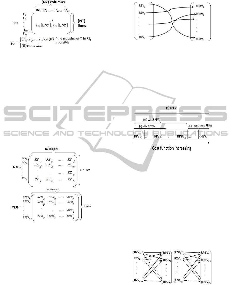
Figure 3: Occupation rates matrix.
4.2 Step 2: Random Construction of the
Matrix of RZs and RPBs
In this step, we target to prepare the n RZVs and n
RPBVs. As showed in Figure 4, we generate the ma-
trices MRZ and MRPB containing respectively n dif-
ferent RZVs and n different RPBVs. MRPB takes into
account the overlapping constraint (CP1): A combi-
nation of RPBs depicted by one line of MRPB must
not contain overlapped RPBs. The two matrices have
the same dimension: n lines and NZ columns.
In Figure 4, a, b, c, d and e are naturals in [1,NZ] and
p, q, r, s and t are naturals in [1,NPB].
Figure 4: The matrices of the RZs and RPBs.
4.3 Step 3: Place Randomly the RZs on
the RPBs
As depicted in Figure 5, this step, by analogy to the
random bees’ exploration of the flowers patches, in-
volves placing randomly the RZVs on the RPBVs.
During the placement, we must take into account the
possibility of placement by checking that there are
enough resources in RPB to execute the RZ and the
fact that an RPB can contain only one RZ.
Figure 5: Random placement of the RZs on the RPBs.
4.4 Step 4: Sort the RPBVs According
to the Cost Function
This step begins by sorting RPBVs in an ascending
order according to the cost function. Then, we select
the m best RPBVs among which we choose the e elite
RPBVs. Figure 6 illustrates the RPBVs sort.
Figure 6: The RPBVs sort.
4.5 Step 5: Generate the Matrices of the
Elite and Best RPBVs
Like in the colony of bees which assigns a big num-
ber nep of bees to the e elite patches, we place nep
RZVs on each elite RPBV from the e elite RPBVs
and then determine the RZV ensuring the minimum
cost function for each RPBV. Similarly, on each best
RPBV from the (m-e) best RPBVs, we place nsp RZVs
(nsp < nep) and we also determine the RZV ensuring
the minimum cost function for each RPBV. Figure 7
shows these placements.
According to these placements, we construct the
Figure 7: Placement of (nep) RZVs on the (e) elite RPBVs
and (nsp) RZVs on the (m-e) best RPBVs.
matrices EliteFitnessMatrix and SelectedFitnessMa-
trix which contain respectively the cost functions of
the elite and best RPBVs. Figure 8 and Figure 9 indi-
cate these matrices.
PECCS 2011 - International Conference on Pervasive and Embedded Computing and Communication Systems
502
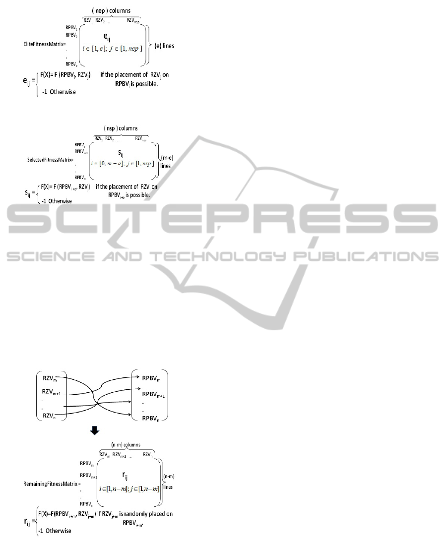
Figure 8: The matrix of the elite RPBVs.
Figure 9: The matrix of the best RPBVs.
4.6 Step 6: Generate the Matrices of the
Remaining RPBVs
By analogy to the Bees Algorithm which assigns the
(n − m) remaining bees to search randomly the nectar
in the (n − m) remaining patches, we place arbitrarily
the (n − m) remaining RZVs on the (n − m) remain-
ing RPBVs. Then, as showed in Figure 10, we gen-
erate the matrix RemainingFitnessMatrix which con-
tains the cost functions resulting from these place-
ments.
Figure 10: The matrix of the remaining RPBVs.
4.7 Step 7: Generate the Matrices of the
Elite and Best RPBVs
After each iteration from the Nitr ones, we select
the couple (RZV
m
,RPBV
m
) ensuring the minimum of
the cost function e
m
. The value of e
m
is exactly the
minimum of the three matrices: EliteFitnessMatrix,
SelectedFitnessMatrix and RemainingFitnessMatrix.
RZV
m
and RPBV
m
are respectively the correspondents
RZV and RPBV.
We repeat the previous steps (from step 2 to step
7) Nitr times and we keep the results of each itera-
tion (the minimum of the cost function e
m
and the
couple (RZV
m
,RPBV
m
)) in a three dimensional ta-
ble: TBEE. Therefore, TBEE contains Nitr elements.
Then, we choose the minimum of the cost function
from this table e
min
and the correspondent couple
(RZV
min
,RPBV
min
). We also repeat the previous steps
(from step 1 to step 7) Nitrmapping times and we
keep, after each iteration, the results obtained next to
the Nitr iterations: e
min
and the correspondent cou-
ple (RZV
min
,RPBV
min
) in a three dimensional table:
TGLOBAL. Thus, the size of TGLOBAL is Nitrmap-
ping. Then, we choose the final solution which is the
minimum of the cost function in TGLOBAL: e
opt
and
the correspondent couple (RZV
opt
,RPBV
opt
).
In our approach, the tasks with the same type are
grouped in RZs. Thus, placing an RZ means plac-
ing a set of tasks at once unlike the off-line place-
ment method in (Danne and Stuehmeier, 2005) which
handles tasks independently from each other leading
to the increase of the tasks’ rejection. In addition, if
we have a big number of tasks, the complexity of the
problem in the proposed method will be small com-
pared to Danne and Stuehmeier method as the num-
ber of RZs to place is fewer than that of tasks. Also,
we take into consideration the preemptions of tasks
and the overheads which is not the case in (Danne
and Stuehmeier, 2005). Besides, we integrate the
whole problem in a single heuristic while the method
in (Danne and Stuehmeier, 2005) uses three heuristics
to validate only its first step of placement.
5 EXPERIMENTAL RESULTS
To illustrate the proposed method, we have imple-
mented an application composed of hardware tasks
that are frequently used in the recent embedded sys-
tems performing video and audio applications. This
application is characterized by hardware tasks of var-
ied sizes and of heterogeneous resources. The hard-
ware tasks are centralized around the microcontroller
(T48) which configures these tasks and synchronizes
the data flow. During the design of this application,
we have synthesized the resources of each hardware
task by the Xilinx tool ISE 11.3 and we have de-
termined the configuration overheads of the obtained
RZs by performing the partial reconfiguration flow by
PLACEMENT OF HARDWARE TASKS ON FPGA USING THE BEES ALGORITHM
503
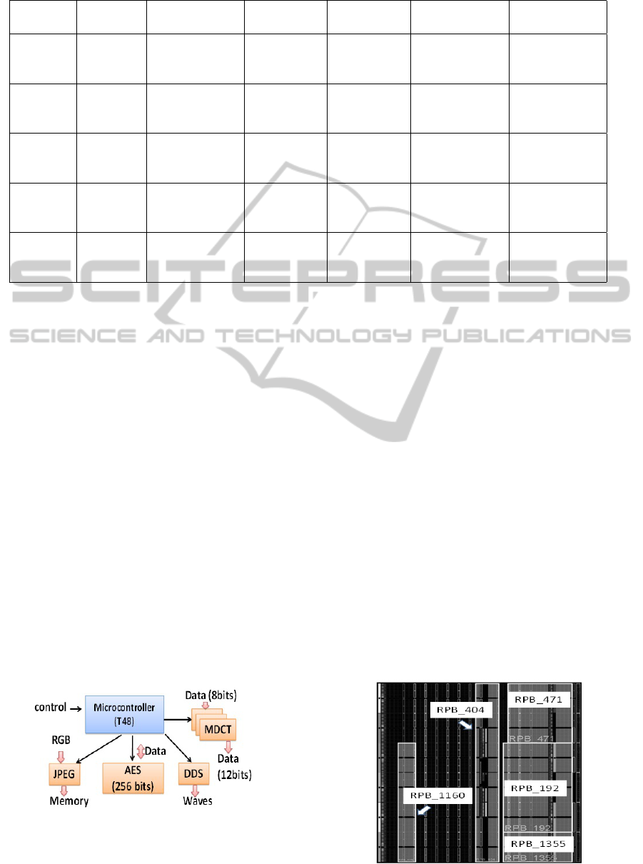
Table 1: Hardware tasks features.
Modules Instances RBs WCET (µs) Period (µs) Configuration
overhead (µs)
Pre-emption
points (µs)
MDCT {T
1
,T
2
} {2RB
1
,
12RB
2
,
3RB
3
, 0RB
4
}
40552 416666 1856 10000,
20000, 30000
AES {T
3
} {4RB
1
,
7RB
2
, 1RB
3
,
1RB
4
}
51540 100000 2185 30000, 40000
DDS {T
4
,T
5
} {0RB
1
,
1RB
2
, 1RB
3
,
1RB
4
}
5000 12000 432 1000, 2000,
4000
T48 {T
6
} {5RB
1
,
4RB
2
, 0RB
3
,
0RB
4
}
20000 50000 605 5000, 10000,
15000
JPEG {T
7
} {8RB
1
,
12RB
2
,
0RB
3
, 2RB
4
}
350000 416666 2421 200000,
300000
means of Xilinx tool Planahead 11.3 and by taking
into account I/O routing.
Figure 11 indicates the hardware tasks compos-
ing the application and the microcontroller T48 which
manages these tasks. The AES (Advanced Encryp-
tion Standard) task encrypts blocks of 20 Kbytes us-
ing a key of 256 bits. The MDCT module calculates
the Modified Discrete Cosine Transform. JPEG task
provides a hardware compression of 24 frames per
second. The DDS (Direct Digital Synthesizer) mod-
ule generates sinusoidal and programmable waves
with adjustable frequency and phase. The character-
istics of hardware tasks and their instances are pre-
sented in Table 1. These RBs are determined taking
into account the reconfiguration granularity and the
resources area in Virtex 5 technology (Xilinx, 2009).
It contains 4 main types of resources CLBL, CLBM,
BRAM and DSP. Therefore, RB
1
is 20 CLBL s, RB
2
is 20 CLBMs, RB
3
is 4 BRAMs and RB
4
is 8 DSPs.
The preemption points are generated arbitrarily and
based on the granularity and the WCET of the hard-
ware tasks. For all the tasks, we consider that the first
preemption point is equal to 0 µs.
Figure 11: Hardware tasks of the application.
The parameters of the Bees Algorithm cho-
sen to solve this problem are the following:
NiterMapping = 5, Nitr = 2, n = 6, m = 4, e = 2,
nep = 4 and nsp = 2.
Table 2 shows the RZs (Virtex 5 SX50T) and the
number of possible RPBs. The good solution, re-
sulting from the proposed method, is showed in Ta-
ble 3. It indicates the different execution sections of
the tasks mapped on the RZs which are placed on the
RPBs. This solution optimizes the parameters of the
placement/mapping problem by minimizing the cost
function (F). To illustrate the proposed method, we
vary the parameter NiterMapping which represents
the number of repetitions of the Bees Algorithm. We
note that the more we repeat the Bees Algorithm, the
more the cost function reduces.
Figure 12 depicts the floorplanning of RPBs on the
technology Virtex 5.
The RPBs are so limited on the device so that we
optimize the exploitation of resources and we avoid
the resources waste. Thus, we preserve sufficient
space for the static design. This optimization in use
of resources minimizes the reconfiguration overhead
of FPGA.
Figure 12: Floorplanning of RPBs on Virtex 5 SX50T.
PECCS 2011 - International Conference on Pervasive and Embedded Computing and Communication Systems
504

Table 2: The number of RZs and possible RPBs.
RZs RBs Number of pos-
sible RPBs
RZ
0
{2RB
1
,12RB
2
,
3RB
3
,0RB
4
}
415
RZ
1
{4RB
1
,7RB
2
,
1RB
3
,1RB
4
}
534
RZ
2
{0RB
1
,1RB
2
,
1RB
3
,1RB
4
}
294
RZ
3
{5RB
1
,4RB
2
,
0RB
3
,0RB
4
}
617
RZ
4
{8RB
1
,12RB
2
,
0RB
3
,2RB
4
}
410
Table 3: Results of the Bees Algorithm.
RZ RPB Tasks Occupation
rate of RZ
RZ
4
RPB
192
T
7,1
,T
7,2
,T
7,3
(100%o f T
7
)
83,1776%
RZ
0
RPB
404
T
1,1
,T
1,2
,T
1,3
,T
1,4
(100%o f T
1
)
T
2,1
,T
2,2
,T
2,3
,T
2,4
(100%o f T
2
)
19,306%
RZ
1
RPB
471
T
3,1
,T
3,2
,T
3,3
(100%o f T
3
)
T
4,1
,T
4,2
,T
4,4
(83%o f T
4
)
85,8802%
RZ
3
RPB
1355
T
6,1
,T
6,2
,T
6,3
,T
6,4
(100%o f T
6
)
40,0484%
RZ
2
RPB
1160
T
4,3
(17%o f T
4
)
T
5,1
,T
5,2
,T
5,3
,T
5,4
(100%o f T
5
)
48,5133%
6 CONCLUSIONS
In this paper, we propose a heuristic method to solve
the problem of hardware tasks placement on FPGA
technology (Virtex 5) based on the Bees Algorithm.
We tried to optimize the parameters of this con-
strained optimization problem so that we reduce the
cost function. We also avoid the tasks rejection as we
pack tasks on RZs and we employ the dynamic par-
tial reconfiguration. Our experimental results show
the efficiency of this method in terms of resources and
reconfiguration overhead.
We plan in a future work to propose another method
and to compare it with the Bees Algorithm. Also, we
will exploit the results of this off-line placement to
achieve an on-line scheduling of the tasks taking into
account the inter-task communication and real time
constraints.
ACKNOWLEDGEMENTS
The authors would like to thank the national agency
of research in France and the world-ranking Secured
Communicating Solutions (SCS) cluster that sponsor
our research project FOSFOR. This work was sup-
ported by AIMMS technical support and Xilinx tools.
REFERENCES
Ahmadinia, A., Bobda, C., Bednara, M., and Teich, J.
(2004). A new approach for on-line placement on re-
configurable devices. International Parallel and Dis-
tributed Processing Symposium (IPDPS), Santa Fe,
NM, U.S.A., page 134.
Bazargan, K., Kastner, R., and Sarrafzadeh, M. (2000). Fast
template placement for reconfigurable computing sys-
tems. IEEE Design and Test, Special Issue on Recon-
figurable Computing, pages 68–83.
Danne, K. and Stuehmeier, S. (2005). Off-line placement
of tasks onto reconfigurable hardware considering ge-
ometrical task variants. IFIP conference.
FOSFOR (2010). Fosfor project, 2010.
http://www.polytech.unice.fr/ fmuller/fosfor.
Handa, M. and Vemuri, R. (2004). An efficient algorithm
for finding empty space for online fpga placement.
Design Automation Conference (DAC), San Diego,
California, USA, pages 960–965.
Marconi, T., Lu, Y., Bertels, K., and Gaydadjiev, G. (2008).
Task placement algorithm for partial reconfigurable
systems. Design Automation Test Europe (DATE),
Munich, Germany, pages 1346–1351.
Pham, D. and Ghanbarzadeh, A. (2007). Multi-objective
optimisation using the bees algorithm. Proceedings of
IPROMS, Cardiff, UK.
Pham, D., Ghanbarzadeh, A., Koc, E., Otri, S., Rahim, S.,
and Zaidi, M. (2006). The bees algorithm - a novel
tool for complex optimisation problems. Proceedings
of IPROMS, Cardiff, UK.
Pham, D., Haj Darwish, A., Eldukhri, E., and Otri, S.
(2007a). Using the bees algorithm to tune a fuzzy
logic controller for a robot gymnast. Proceedings of
IPROMS, Cardiff, UK.
Pham, D. T., Afify, A., and Koc, E. (2007b). Manufactur-
ing cell formation using the bees algorithm. IPROMS
conference.
Xilinx (2009). Xilinx, 2009. virtex-5 fpga configuration
user guide. Technical report.
PLACEMENT OF HARDWARE TASKS ON FPGA USING THE BEES ALGORITHM
505
