A
UTOMATIC MULTI-PROJECTOR CALIBRATION
A Review of Systems for Non-experienced Users
Stefan Klose, J
´
er
´
emie Gerhardt
Fraunhofer FIRST, Kekul
´
estr. 7, 12489 Berlin, Germany
Timo Engelke, Arjan Kuijper
Fraunhofer IGD, Fraunhoferstr. 5, 64283 Darmstadt, Germany
Keywords:
Multi-Projector Systems, Three-Dimensional Graphics and Realism, Virtual Reality, Camera Calibration.
Abstract:
Multi-projector systems are widely used in many application areas. Such systems are for instance employed to
increase the brightness or the resolution of projected images. Intrinsic to multi-projector systems are problems
like geometric misalignment, especially when projecting onto complex arbitrarily formed projection surfaces,
and photometric deviations. Therefore, several difficult calibration tasks (geometry, brightness, color) have to
be performed. A high-quality and easy-to-use calibration process is the key to good usability for untrained
or unexperienced users. Due to the fact that manual calibration is time-consuming and imprecise, automatic
approaches were developed in recent years. This paper analyzes the most popular state-of-the-art algorithms
and setups with respect to their advantages and disadvantages. We summarize the general working principles
of calibration algorithms and provide an outlook into the fields in which the described algorithms are most
useful.
1 INTRODUCTION
Projection systems are widely used in many appli-
cation areas of industry, research and development,
art and culture or teaching. Single-channel systems
are not adequate for more complex use cases that
aim to increase the brightness or resolution, display
three-dimensional stereoscopic content, obtain redun-
dancy, or guarantee a focused projection on a three-
dimensional projection surface. Therefore, multi-
projector systems are utilized. However, without
adaptations the partial projections of such a system do
not form a homogeneous projection. Visible artifacts
due to pixel offsets, brightness differences, and devia-
tions from the geometry of the projection surface may
occur.
In order to eliminate those effects a multi-
projector system has to be calibrated in pixel-perfect
fashion. In most cases this calibration is a non-trivial
task that has to be solved with manual, semiautomatic
or fully automatic algorithms.
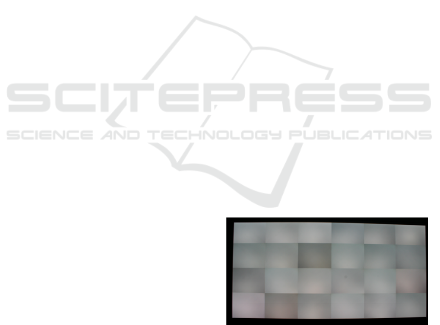
In general, the following problem has to be solved:
An arbitrarily formed projection surface will be illu-
minated by a projector cluster. The projectors are only
roughly aligned, yielding a view that clearly shows
Figure
1: Uncalibrated projector setup.
the different projectors; see for an example Figure 1.
The goal of calibration algorithms is to achieve a ho-
mogeneous projection that looks like it was projected
only from one device. Therefore, several calibration
tasks have to be solved:
1. Geometry Correction: Adjustment of the projec-
tors with respect to each other and a camera or
other reference systems, such as the projection
surface itself.
2. Vignetting and Brightness Correction: Adjust-
ment of the projectors’ visible brightness fall-off
and brightness deviations that occur in overlap-
286
Klose S., Gerhardt J., Engelke T. and Kuijper A..
AUTOMATIC MULTI-PROJECTOR CALIBRATION - A Review of Systems for Non-experienced Users.
DOI: 10.5220/0003356702860295
In Proceedings of the International Conference on Computer Graphics Theory and Applications (GRAPP-2011), pages 286-295
ISBN: 978-989-8425-45-4
Copyright
c
2011 SCITEPRESS (Science and Technology Publications, Lda.)
ping regions or result from the projection angle or
the projector type.
3. Color correction: Adjustment of deviations in the
overall chromaticity due to aging lamps or differ-
ent projector models.
These three tasks should be solved in such a way
that a multi-projector system provides best visual
quality with minimal setup costs. There should be
no time consuming manual tasks but an automatic ap-
proach instead, using measurement devices like digi-
tal cameras.
The aim of this paper is to provide a comparison of
such approaches with respect to utilization for users
without too much experience. To our best knowl-
edge there is currently no such paper available. It
will help both experienced and inexperienced users to
choose appropriate calibration methods or to improve
their own algorithms. For some older more technique-
focused in-depth surveys on multi-projector displays
and (vision-based) calibration techniques we refer to,
for example, (Majumder and Brown, 2007; Brown
et al., 2005; Ni et al., 2006; Bimber et al., 2008; Bim-
ber and Raskar, 2005; Li et al., 2004; Pollefeys et al.,
1999).
In the remainder we present the essential com-
ponents of a multi-projector system, followed by the
more general principles of calibration. The most pop-
ular dedicated state of the art automatic algorithms are
discussed in section 4. Subsequently, we list their ad-
vantages and disadvantages, again from the point of
view of untrained users, and provide application ex-
amples in which the described techniques can be used.
We complete this paper with a short conclusion.
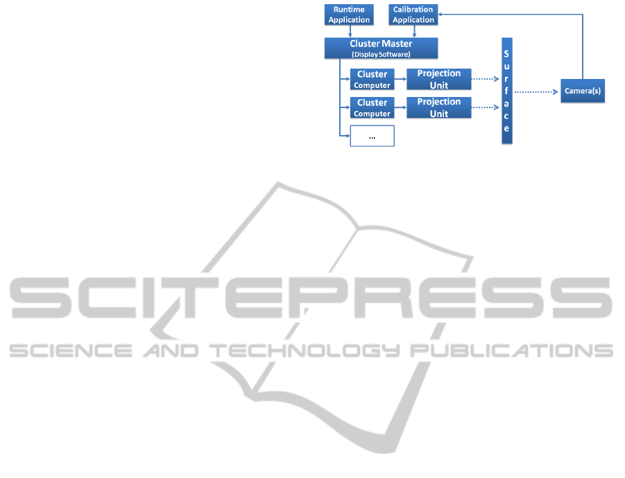
2 SYSTEM SETUP
In multi-projector setups we usually deal with high
resolution content that shall be displayed in real time.
Bandwidth problems in transferring the image infor-
mation to the projection unit usually appear. Thus a
common approach is to cluster the system, running
multiple render units connected to the projectors and
creating the resulting image, see Figure 2.
One or multiple cameras capture the projection
surface and work with the calibration application and
the clustering master in order to create proper cali-
bration data. These data will be used by designated
applications, which are rendered through the cluster
machines. In this section we describe the general op-
tions in configuring multi-projector setups.
Figure 2: Generalized Setup Components.
2.1 Cluster Setup
A cluster usually consists of a distributed rendering
system with at least one master. The master dis-
tributes the information to be displayed to the clients
– the cluster machines. Mainly the clients are used for
applying the rendering loop. The cardinality between
projector and render machine can be chosen freely,
but should be consistent throughout the entire con-
figuration. In order to configure and setup viewing
and calibration parameters, clients and master must be
able to communicate with each other. Already exist-
ing frameworks are for example (Fellner et al., 2009;
Isakovic et al., 2002).
Technologies like Remote Desktop Applications
(RDP, VNC, etc.) are a way for transmission of con-
tent in such a cluster. These technologies deliver con-
tent but can be ineffecient or incapable on high den-
sities of information, like multimedia or 3D-Content,
since there is no hardware abstraction.
One possible solution for effiecient hardware ab-
straction is Chromium (aka. WireGL (Humphreys
et al., 2001)), which simulates a network-bound
graphics card and smartly distributes the OpenGL
commands via network to the clients. The main ad-
vantage is the compatibility with older OpenGL soft-
ware. The disadvantage comes with maintenance of
the large and constantly changing OpenGL standard
(Humphreys et al., 2008).
Scene graph distribution delivers the main advan-
tage by being a complete abstraction of hardware
standards and at the same time delivering parts of the
scene graph description through the network at high
performance. Additionally this method can be com-
bined with image-based distribution, allowing load
balancing within the cluster (Roth et al., 2006). Both
2D and 3D applications can be realized with such a
system. A main disadvantage is the insufficient sup-
port of standard applications. This can be compen-
sated by rendering X-Window drawing commands or
RDP as textures. An abstract language definition al-
lows the description of the main application (Behr
AUTOMATIC MULTI-PROJECTOR CALIBRATION - A Review of Systems for Non-experienced Users
287

et al., 2007).
A potential problem of display in a cluster is the
synchronization of the vertical sync signal of all video
outputs. On fast moving scenes it can prevent the par-
tial simulcast display of two consecutive images. Pro-
fessional graphic cards therefore support gen locking
(NVidia, 2010). Another solution is using custom-
built software/hardware (Allard et al., 2003).
2.2 Projector Devices
Different projection technologies can change the ap-
proach for calibration. Generally there is a need for
stability in terms of light intensity, colors and resolu-
tion.
A good contrast and black value is important. Oth-
erwise, especially when projecting dark scenes with
projector clusters, the effect of a homogeneous pro-
jection vanishes. LCD (Liquid Christal Display) usu-
ally delivers a bad contrast, while newer technologies
like LCoS (Liquid Crystal on Silicon) and SLP (Spa-
tial Light Modulators aka DLP or DMD) gain much
better contrast.
3D projections can have an impact on the cali-
bration as well. Passive frequency shifting systems
like Infitec (Infitec, 2010) need to be setup with
stacked projectors, which leads to loss of pixels. Ad-
ditionally the color space in such systems is reduced.
Newer systems, like RealD (RealD, 2010) or active
approaches like presented in (Havemann et al., 2007)
are using only one projector. Therefore, the latter sys-
tems have a huge impact in hardware for synchroniz-
ing each eye in multi-projector setups.
2.3 Projection Setups
Depending on the field of application, several projec-
tion setups or a combination of them are utilized:
• Stacked Projection: At least two projectors illumi-
nate the same area of the projection surface to in-
crease the overall brightness, for redundancy rea-
sons, to facilitate 3D-stereoscopic projections, or
to increase the usable color space.
• Mosaicked or tiled projection: At least two pro-
jectors are aligned side by side or one upon the
other to increase the overall resolution. The com-
bination of vertically and horizontally adjusted
components is also possible. The uncalibrated and
overlapping projections can form a relatively reg-
ular or an irregular grid. Depending on the size
of the overlapping regions soft-edge or hard-edge
blending will be deployed.
Hard-edge blending does not allow the physical
overlap of adjacent projections. It demands a huge
effort in hardware and manual calibration while
coping with projectors having a bad black value.
Soft-edge blending compensates the addition of
light in the overlapping regions by modifying the
input images accordingly.
• Windowed Projection: Several independent pro-
jection surfaces or a plurality of monitors are
used. This is similar to a mosaicked projection
but without any overlapping regions at all. Due
to those gaps the overall projection appears like a
window to a virtual world. When using at least
two projectors the overall resolution is increased,
as well.
In the first two cases the spatial, geometric, and
colorimetric synchronicity is crucial to create the illu-
sion of a homogeneous projection. The projections
must be aligned in pixel-perfect and synchronous
fashion to prevent fuzzy or even doubled images,
which can lead to headaches (Pastoor, 1995). In the
latter case, the projections should also be aligned with
respect to their window.
2.4 Measurement Devices
Measurement is typically used in some kind of con-
trol system, where the input of the visible image is
fed back into the control system and changes the ap-
pearance of the displayed content. Typical setups are
using one (Bimber et al., 2005; Klose, 2009), multi-
ple static (Raskar et al., 2006; Dingeldey et al., 2010)
or movable cameras. These are usually used for ei-
ther sampling of calibration patterns or photometric
measurement. For correct chromatic measurements
calibrated colorimeter (Pagani and Stricker, 2007) or
colorimeter cameras (SphereOptics, 2010) are used.
Thus mostly a combination of colorimeter and digi-
tal cameras are used. High Dynamic Range (HDR)
cameras also offer a promising approach for deliver-
ing higher photometric resolution.
In order to achieve good calibration results, the
images taken must be focused and well-exposed. The
capturing must also be reproducible.
3 GENERAL PRINCIPLES OF
CALIBRATION
For the automatic calibration of projectors it is impor-
tant that geometric, brightness and color correction
are processed consecutively as these steps depend on
each other. The result of all processes can be com-
bined in GPU-based shaders and applied within the
render pipeline. Another approach would be to apply
GRAPP 2011 - International Conference on Computer Graphics Theory and Applications
288
the results within a graphic card driver or the projector
engine itself.
3.1 Geometry Correction
As defined previously in this paper, the geometry cor-
rection retrieves the parameters to adjust the projec-
tors with respect to each other, the projection surface
and the observers.
The calibration starts by projecting reference pat-
terns on the surface. The patterns can for example be
fiduciary markers, coded light stripes or binary pat-
terns. Captured images of those projected patterns
are then analyzed by filtering, black image subtrac-
tion, thresholding, or gradient-based contour detec-
tion. This allows registering the projectors with re-
spect to the projection surface in the space of the mea-
suring device.
Two calibration approaches can be compared for
a matter of complexity (calibration with respect to
a camera or to a projection surface). The calibra-
tion with respect to a camera (or observer calibration)
is relatively easy because of its direct mapping from
projector space to camera space:
(u,v) : T
p→c
(x,y) (1)
where (u, v) are the coordinates of projector space in
camera space (x,y). The border of the overall pro-
jection will be set with respect to the camera’s field
of view (i.e. largest inscribing rectangle of the multi-
projection). Because the calibrated image is aligned
with respect to a camera and not to the shape of
the projection surface, this approach is not observer-
independent.
The calibration with respect to a projection sur-
face is more complex because the actual projection
screen has to be reconstructed or detected:
(u,v) : T
c→s
(T
p→c
(x,y)). (2)
This is done by (physical) marker detection, user in-
teraction, model matching, or 3D reconstruction. Be-
cause the calibrated image will be wallpapered across
the projection surface, this approach is observer-
independent.
Once the calibration method is chosen, the warp-
ing parameters (u,v) can be derived. They can be
calculated using global or local approaches. Global
warping applies a homography matrix. This method
assumes a perfect projection surface and can lead to
errors. Local per-pixel warping is more accurate. The
latter can also correct distortions introduced by slopes
and dales of the projection surface.
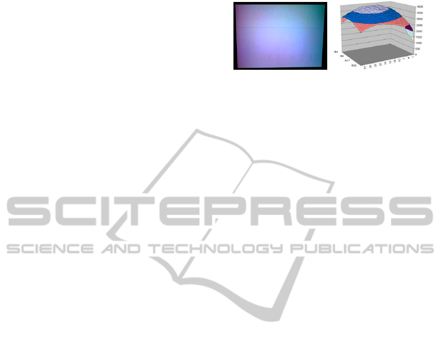
Figure 3: Brightness and luminance profile of one tile.
3.2 Vignetting and Brightness
Correction
Figure 1 already showed an example of an uncali-
brated hard-edge multi-projector setup. In Figure 3
one sees the result of one projector (tile) with the
measured brightness values as well. The general aim
of this correction is gaining uniformity in luminance.
Based on the measured brightness values over all the
partial projections of a multi-projector system, the al-
gorithm has to select the point with the lowest bright-
ness. In order to guarantee uniformity in luminance,
all the projectors in the installation have to be adjusted
to that brightness. The main disadvantage of this ap-
proach is the fact that the dynamic of the brightness
gets lost.
Majumder and Stevens propose a photometric cal-
ibration with simple monochromatic cameras that
need fixable exposure and shutter (Majumder and
Stevens, 2004). A more precise measurement can
be done using Colorimeter cameras which directly re-
sults in absolute CIE coordinates and luminance val-
ues. If a regular camera allows taking high resolution
pictures (and then accurate spatial information) the
direct use of its RGB values should be avoided, es-
pecially if the camera sensors remain unknown (Vora
and Trussell, 1993). One possible approach is tak-
ing a high dynamic range (HDR) image (Debevec and
Malik, 1997) of each ramp level (Pagani and Stricker,
2007) from which only the luminance values are used.
A very universal approach for applying the cali-
bration is the use of a 3D look-up table (LUT) per pri-
mary color channel represented in two dimensions for
the pixel location and for the pixel level adjustment.
This is common sense as it can easily be implemented
in GPU shaders or is supported by a variety of profes-
sional projector engines. In order to compute a LUT
for each projector, the following operation needs to be
repeated: project and measure ramps of pure red (R),
green (G) and blue (B). With this information the re-
sponse curves of a projector can be measured (global
and per color channel) and its gamma value can be de-
termined. A typical response curve is a gamma shape:
x
γ
, where x is between 0 and 1 and γ approximately
between 2 and 3.
AUTOMATIC MULTI-PROJECTOR CALIBRATION - A Review of Systems for Non-experienced Users
289

In a tiled display installation with overlapping pro-
jections, soft-edge blending has to be performed addi-
tionally. The geometrical calibration provides the in-
formation on overlapping regions which can be used
for the blending. Soft-edge blending reduces the
brightness in the overlapping regions such that it is
as bright as the rest of the global projection. This is
done by cross-fading the light intensity between the
projectors with a proper blending function. A sigmoid
blending function offers a more subtle transition be-
tween blended and unblended areas compared to lin-
ear blending. The following example applies to two
overlapping projectors:
f (x) = sin
³
xπ −
π
2
´
0.5 + 0.5
g(x) = sin
³
−xπ +
π
2
´
0.5 + 0.5 (3)
where the results have to be gamma-corrected by the
projectors’ known exponential factors 1/γ or by their
inverse response curve function.
3.3 Color Correction
This operation requires estimating the common gamut
of the installation, i.e. defining what the common
displayable colors of the projectors are (Pagani and
Stricker, 2007; Bern and Eppstein, 2003; Wallace
et al., 2003). The CIE XYZ primary values of each
projector are computed from the measured corre-
sponding spectral reflectances.
Once the common gamut is defined, the gamut
mapping operation is performed by a matrix opera-
tion. For each projector the new RGB values will be
computed that map to the same (global) XYZ values.
The great advantage of a gamut mapping operation is
that it ensures that color differences are not visible to
the human eye. But it can also drastically reduce the
color dynamics. The following equation demonstrates
how the RGB values are modified before projection:
c
0
= g
−1
p
(M
p
M
c
c
γ
) (4)
where M
p
is the matrix of one projector, M
c
is the
matrix characterizing the common gamut, c
γ
the cor-
responding RGB values for the installation response
curve (which is defined by the user) and g
−1
p
(c) the
inverse response curve function of projector p.
4 CALIBRATION ALGORITHMS
We have described the general working principles of
automatic calibration algorithms. Now we present se-
lected state-of-the-art algorithms utilizing these prin-
ciples. Again, we focus on automatic approaches
only. We provide a short description and evaluate the
algorithms regarding unique characteristics and ad-
vantages, accuracy, simplicity and drawbacks.
4.1 iLamps/Display Grids (iL/DG)
Short Description: Raskar et al. have developed sev-
eral automatic multi-projector calibration algorithms.
Notable approaches are iLamps (Raskar et al., 2006)
and Display Grids (Raskar et al., 2004).
The system consists of several autonomous pro-
jectors that build ad-hoc clusters. Projectors can be
registered and non-registered dynamically. The used
projectors are modified and enhanced with a camera,
a tilt sensor, a wireless communication module, and
a computer. With the help of those additional mod-
ules, the topology of the projectors and their geomet-
ric neighborhood will be detected. This information
leads to an automatic geometric correction including
blending.
Using the integrated camera, the 3D depth of the
projection surface at certain manually-aligned cali-
bration markers is triangulated using structured pat-
terns. Not only the projector that contains the cam-
era but the adjacent projectors are taken into account.
Under the assumption that the projection surface is a
vertical plane or a vertical quadric, the deviation from
the world horizontal and vertical can be determined
using the integrated tilt sensor. The triangulation data
and the tilt values are used to calculate homography
matrices for each projector. Applying those matri-
ces corrects the projector distortions with respect to
their neighborhood and the desired parallelism to the
world horizontal and vertical. A similar method was
described in (Webb and Jaynes, 2007).
Unique Characteristics and Advantages: Self-
configuring ad-hoc clusters using projectors with in-
tegrated cameras are an excellent way to create seam-
less tiled projections with very large aspect ratios.
Accuracy: For the triangulation the projector-camera
system has to be perfectly calibrated. An imprecise
system calibration leads to significant 3D reconstruc-
tion errors. The use of global homography matrices
implies projection errors because those methods as-
sume perfect planes or quadrics. This assumption is
often insufficient in reality and is also described in
(Okatani and Deguchi, 2006).
Simplicity: The system extensibility is very good
due to the automatic registration and non-registration.
The use for the modified projectors leads to a very
simple setup process. The simplicity is unfortunately
decreased by using manually aligned physical mark-
ers.
Drawbacks: Modified projectors are still no off-the-
GRAPP 2011 - International Conference on Computer Graphics Theory and Applications
290

shelf product. Therefore, the modified projectors have
to be assembled and calibrated very carefully. Oth-
erwise the projection would suffer from substantial
errors. Due to the used homography matrices, the
method is only applicable to perfect surfaces or a sec-
ond per-pixel post warp is needed. The partial projec-
tions and their corresponding camera images, respec-
tively, have to overlap to detect neighboring projec-
tions. Therefore, the previously described windowing
setup is limited or impossible.
4.2 Embedded Light Sensors (ELS)
Short Description: An automatic calibration method
that adjusts the projection with respect to a reference
projection surface was developed by Lee at al. (Lee
et al., 2004).
In contrast to most other automatic approaches it
uses no digital camera, but light sensors that are em-
bedded at the corners or other feature points of the
projection surface. Due to the low amount of used
sensors a per-pixel calibration is not possible. To
determine the geometrical relation between projector
and projection surface, a homography transformation
matrix is calculated. For this, several pixel-to-sensor
relations have to be measured. A relation implies that
a certain projected pixel illuminates a certain sensor.
To measure these relations an iteratively refining bi-
nary pattern is projected. Once the relations between
sensors and projected pixels are known, the homog-
raphy matrix can be determined. Applying this ma-
trix in real-time on the projected image leads to the
projection fitting in the projection surface. Embedded
sensors are also used by 3D Perception (3DPercep-
tion, 2010).
Unique Characteristics and Advantages: No dig-
ital camera is needed because the projection surface
itself measures the distortions via embedded light sen-
sors. The projection is observer-independent because
it is aligned with respect to a rectangular reference
plane.
Accuracy: When using perfect planes this method
implies a high quality.
Simplicity: When abstracting from modifying the
projection surface with the sensors, it is a very easy-
to-use method. The calibration can be triggered by
simply holding the projection surface into the projec-
tor’s frustrum.
Drawbacks: A crucial drawback of this algorithm is
the applied global homography transformation. If the
projection surface contains slopes and dales or is bent
a homography is not sufficient anymore due to the
errors that result from the difference between global
transformation and local deviations. This particularly
applies to multi-projector systems. Therefore, a per-
fect projection surface is needed. Also a modified
projection surface is needed.
4.3 Smart Projectors (SP)
Short Description: The Smart Projector technology
was developed by Bimber et al. (Bimber et al., 2005).
Meanwhile it is distributed by the company Vioso un-
der the name Vioso Presenter. Vioso particularly spe-
cialized in extreme case projections like structured
walls, colored wallpapers, curtains, or rocks.
The system is capable of correcting geometric and
photometric distortions. Therefore, structured light is
projected and captured with a digital camera. Due
to the placement of the projectors or the structure of
the projection surface, the calibration patterns are dis-
torted. Those distortions are also visible in the cam-
era’s image plane. Because the method assumes that
camera and observer position are identical, it corrects
the distortion with respect to the image plane. Due
to the projected structured light the position of each
pixel on the projection surface is known and is stored
in a look-up-table. Furthermore, the desired undis-
torted projection with respect to the image plane is
also known. It is a rectangular projection, that shares
the content’s aspect ratio, that is parallel to the im-
age frame, and is also within the distorted projection.
Hence for every projected pixel, an distortion correc-
tion vector and a photometric correction value can be
calculated and stored within a look-up -table. The
correction of the projected content is done in real-
time using pixel shaders. Similar algorithms were de-
scribed in (Klose, 2003) and (Majumder and Brown,
2007).
Unique Characteristics and Advantages: The algo-
rithm offers a fast and precise correction of geometric
and photometric distortions on markerless, arbitrarily
formed projection surfaces.
Accuracy: Due to the dense sampling with structured
light the calibration is very accurate.
Simplicity: Uncalibrated projectors are used for this
method. Due to the assumption that camera and ob-
server position are identical, there is no need for a
system calibration that determines the relationship be-
tween camera and projectors. No further markers or
knowledge about the projection surface is needed.
Drawbacks: As mentioned before the method as-
sumes that camera and observer position are identi-
cal. Therefore, the camera has to be placed very care-
fully. When projecting onto highly distorted surfaces
such as corners, the corrected image will always ap-
pear to be wrong, because it is aligned with respect to
the flat image plane and not with respect to the three-
AUTOMATIC MULTI-PROJECTOR CALIBRATION - A Review of Systems for Non-experienced Users
291

dimensional structure of the projection surface.
4.4 Markerless View-independent
Registration of Multiple Distorted
Projectors on Extruded Surfaces
(MVIRoMDPoES)
Short Description: Sajadi and Majumder devel-
oped an algorithm for markerless, view-independent,
camera-based registration of multiple distorted pro-
jections on extruded projection surfaces (Sajadi and
Majumder, 2009).
Their method works for projection displays de-
fined by a 2D curve (profile curve) that is vertically
extruded and limited by two virtual horizontal planes.
The aspect ratio of the rectangle that is shaped by the
four corners of the projection surface is also known.
In the first step of the algorithm, the intrinsic and
extrinsic parameters of the camera are determined. A
first guess, using the known focal length of the cam-
era, is optimized using the four corners, and is stored
in a camera matrix. Secondly, with the help of this
matrix display parameters are recovered. Samples
on the upper and lower border of the projection sur-
face (in the image plane) are reprojected and inter-
sected with the two virtual horizontal planes. This
leads to two curves in 3D space that will be aver-
aged. A parametric representation of those curves is
found using polynomial curve fitting. In the last step,
a mapping from projector coordinates to display co-
ordinates via camera coordinates is found. The corre-
spondence between projector and camera coordinates
is defined using rational Bezier patches. For this,
blobs are projected, whose positions in the projector
space are known and that map to uv-coordinates in
the camera space. Then rays are cast through those
coordinates and intersected with the 3D model. This
leads to 2D correspondences with the display coordi-
nates, that are used to correct the distorted projection.
In (Sajadi and Majumder, 2010) the method was ex-
tended for displays containing discontinuities, such as
corners.
Unique Characteristics and Advantages: The
method is one of the first algorithms for markerless
calibration of 3D surfaces. Due to the calibration with
respect to the actual shape of the projection surface it
is observer-independent.
Accuracy: Due to the sparse sampling per-pixel cali-
bration will only be achieved if the actual display does
not contain local deviations from the expected shape.
Simplicity: Because of the markerless approach a
complex and time-consuming setup is not necessary.
The camera can be placed relatively freely. There is
no extra system calibration because the calculation of
those parameters is part of the algorithm itself.
Drawbacks: Currently the method requires user
feedback. The blobs are partly registered by hand.
The algorithm also assumes a linear camera. Using
camera lenses with radial distortions leads to small er-
rors. For geometric registration the projection has to
be entirely inside the projection surface. Therefore, a
rimless projection is not possible. Due to the sparse
sampling local errors cannot be corrected.
4.5 Constraint-based
3D-Reconstruction with Automatic
Calibration (AutoCalib3D)
Short Description: An automatic, camera-based,
markerless calibration method was developed by
Klose. It calibrates the projection with respect to a
three-dimensional extruded projection surface (Klose,
2009) (Klose, 2010).
The projection surface can be described by either
vertical or horizontal, equivalent vectors that stand or-
thogonal on a virtual plane (e.g. a cylinder segment or
a room’s corner). The projection surface itself serves
as the reference system. Therefore, uncalibrated com-
ponents can be used. For scanning the projection sur-
face vertical and horizontal calibration patterns are
projected. The corners and the borders of the display
are detected by projecting white with all the projec-
tors. Therefore, the entire projection has to be larger
than the projection surface.
Due to the knowledge about the projection surface
it is possible to reconstruct its 3D surface from a sin-
gle filtered image of the corners and borders. In a
first step, corresponding points on two opposite bor-
ders are determined by applying a homography trans-
formation to the captured projection surface. After
the homography transformation, the corresponding
points share the same x- or y-value. Those points are
marked within the untransformed image. Then rays
are cast from a virtual camera to the marked points.
The 3D model is calculated by optimizing vectors that
connect the corresponding upper and lower rays until
the conditions are satisfied (equivalent, orthogonal on
a plane). Finally, rays are cast from the virtual camera
to the intersection points of the calibration patterns in
the image plane. To guarantee a rimless projection,
several intersection points outside the projection sur-
face are non-linearly extrapolated. The rays also in-
tersect the 3D model and yield uv coordinates. Subse-
quently, each intersection point’s position in the pro-
jector space and display space is known. Using those
parameters, geometric correction and blending can be
performed in real time.
GRAPP 2011 - International Conference on Computer Graphics Theory and Applications
292
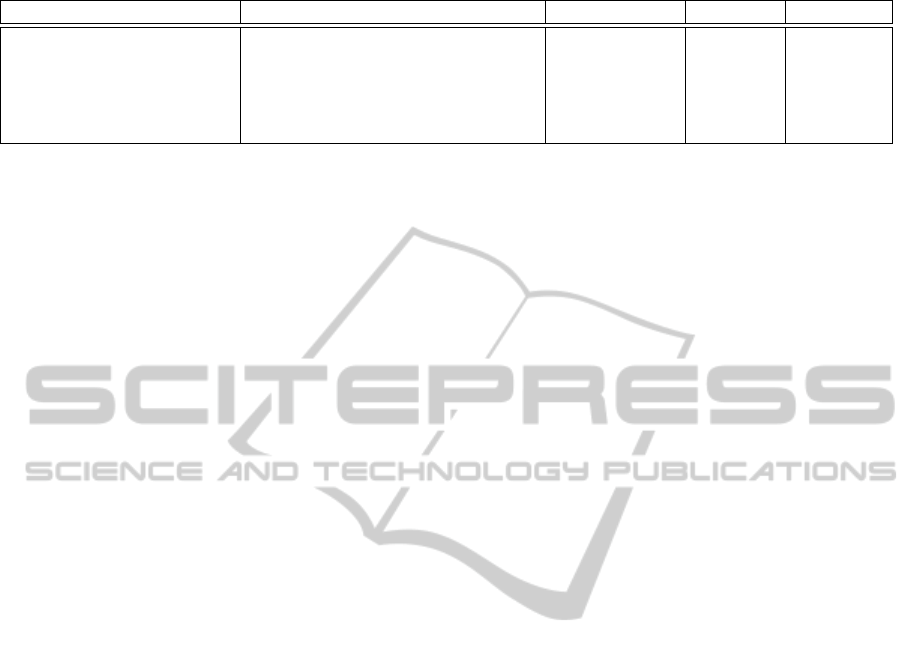
Table 1: Decision support matrix; +: good, o: average, -:bad.
Algorithm Calibration with respect to Warping type Accuracy Simplicity
iL/DG (sec. 4.1) plane, quadric homography - o
ELS (sec. 4.2) plane homography - +
SP (sec. 4.3) camera (arbitrarily formed surface) per-pixel + -
MVIRoMDPoES (sec. 4.4) extruded 3D surface Bezier patches o o
AutoCalib3D (sec. 4.5) extruded 3D surface per-pixel + o
Unique Characteristics and Advantages: This al-
gorithm is also one of the first approaches for mark-
erless calibration of 3D surfaces. It yields a rimless
projection. Even borders of the projection surface are
used for calibrating the camera (ad-hoc lens distortion
correction). The method was derived from perceptual
psychological aspects. It is therefore also observer-
independent.
Accuracy: Due to the dense sampling with calibra-
tion patterns, sub-pixel accuracy is achieved. The pro-
jection surface does not have to be perfect. Deviations
on it will be also corrected.
Simplicity: The markerless approach and the use
of uncalibrated components simplifies the setup
process immensely. No time-consuming mea-
surement of camera-projector-systems or camera-
projectionsurface-system are neccessary.
Drawbacks: In order to achieve a rimless cali-
brated projection, the uncalibrated projection has to
be larger than the projected surface. Hence, pix-
els are lost. If the optimization is aborted prema-
turely (i.e. the global optimum is not found), the 3D
model and the calibration parameters are erroneous.
To achieve good optimization results, the projection
surface should also have a certain ∆ in 3D depth (If a
plane is defined by connecting left and right border of
the projection surface, ∆ is the longest line that is or-
thogonal to this plane and also connects the projection
surface and the plane.).
5 COMPARISON OF THE
APPROACHES - DECISION
SUPPORT
In this section we will compare the most important
properties of the described algorithms (see also Table
1). It also serves as a decision support for potential
users, both experienced and non-experienced ones.
The first column of Table 1 contains the abbrevi-
ations of the described algorithms. The actual cali-
bration will be performed with respect to a reference
system which is stated in column 2. The next column
contains the warping type that is used by the different
algorithms. Column 4 and 5 indicate the accuracy and
the simplicity of the described algorithms.
To decide which of the algorithms is suitable for a
planned installation, the user must first know the type
of the projection surface. Warping type and accuracy
are related, because the latter depends on the first one,
but also on the quality of the projection surface. Un-
der the assumption that the projection surface is not
perfect and contains slopes and dales, a dense sam-
pling of the projection surface leads to a higher accu-
racy. Therefore, per-pixel warping is more accurate
than Bezier patch warping, which is again more accu-
rate than a homography warping. Simplicity depends
on the setup process. Manual user interaction leads to
a decrease in the simplicity score (iL/DG: manually
aligned markers, SP: proper adjustment of the cam-
era). iL/DG can increase its score by utilizing ad-hoc
clustering. The waiver of the camera and the intuitive
calibration with respect to the projection surface leads
to the best simplicity score for ELS. Algorithms 4 and
5 gain a medium score because of the more complex
system setup (compared to ad-hoc clusters). At the
other hand the camera does not have to be placed ac-
curately, because again, the projection surface serves
as the reference system.
5.1 Applications
A variety of interesting setups can be realized with
the described calibration methods, some of which are
mentioned in the following.
Obvious applications are based on the previ-
ously mentioned advantages of multi-projector sys-
tems (e.g. higher resolution, brightness, redundancy).
A high resolution and crisp image is for instance
needed in car design. Outdoor events rely on bright
projections, while redundant projections are essen-
tial for conferences. Stacked and mosaicked cali-
brated displays can be used for those applications.
Stacked projections can also be used to display 3D-
stereoscopic content, where two projectors project the
left and right eye information. Another interesting ap-
plication is the extension of color space by projecting
low and high frequencies with two or more stacked
and calibrated projectors (Boosmann, 2007).
AUTOMATIC MULTI-PROJECTOR CALIBRATION - A Review of Systems for Non-experienced Users
293

Beyond that, interesting art or augmented real-
ity projects are conceivable, like virtual art projec-
tions (Seales and Landon, 2005) or projections onto
buildings (UrbanScreen, 2009). The latter can be uti-
lized as a connection between past, present and fu-
ture. A building can also be “x-rayed” or it can be il-
luminated for entertainment purposes or aesthetic rea-
sons. Augmented projections can also be used in fu-
ture shopping scenarios in which the projection has to
be aligned with respect to the shelves.
Regarding the two methods presented last, eye
catchers are not a nemesis for calibrators anymore.
Such eye catchers can have interesting 3D shapes and
are imaginable at fairs, in entrance halls but also in
art exhibitions or for advertising reasons. More prac-
tical applications like immersive cylindrical displays
or CAVEs are also realizable. The latter can be cal-
ibrated with a divide and conquer strategy with the
described methods.
As one can see there are many exciting applica-
tions. It is also up to the reader to define new applica-
tion areas beyond the ones described here.
6 CONCLUSIONS
In this paper we have presented general aspects, fac-
tors of influence, algorithms, and problems that have
to be dealt with when setting up multi-projector in-
stallations. Often these problems are so multi fold
that expert knowledge is required. In most cases
this is lacking for non-experienced or untrained users.
Within this context we therefore focused on auto-
matic calibration. There is no general recipe for cre-
ating such an installation, requiring again a certain
amount of insight for these non-experienced or un-
trained users. This paper contributes an abstraction of
the main principles and delivers a guide for both expe-
rienced and inexperienced users willing to set up such
a system or improve their methods. It can be applied
in development of multi-projection systems for indus-
try, research, art and culture, or teaching and should
help making the best choice for a specific calibration
problem.
REFERENCES
3DPerception (2010). Simulation. http://www.3d-
perception.com/docs/SimulationLow.pdf.
Allard, J., Gouranton, V., Lamarque, G., Melin, E., and
Raffin, B. (2003). Softgenlock: Active stereo and
genlock for pc cluster. In Proceedings of the Joint
IPT/EGVE’03 Workshop.
Behr, J., D
¨
ahne, P., Jung, Y., and Webel, S. (2007). Beyond
the web browser - x3d and immersive vr.
Bern, M. and Eppstein, D. (2003). Optimized color gamuts
for tiled displays. In SCG ’03: Proceedings of the
nineteenth annual symposium on Computational ge-
ometry, pages 274–281.
Bimber, O., Emmerling, A., and Klemmer, T. (2005). Em-
bedded entertainment with smart projectors. Com-
puter, 38(1):48–55.
Bimber, O., Iwai, D., Wetzstein, G., and Grundhfer, A.
(2008). The visual computing of projector-camera
systems. In ACM SIGGRAPH 2008 classes, Los An-
geles, California: ACM, pages 1–25.
Bimber, O. and Raskar, R. (2005). Spatial augmented re-
ality: merging real and virtual worlds. A. K. Peters,
Ltd.
Boosmann, T. (2007). PhD Thesis: Multispektrale Far-
breproduktion: Projektionssystem und Algorithmen fr
eine additive, multispektrale Farbsynthese. Shaker
Verlag, Aachen.
Brown, M., Majumder, A., and Yang, R. (2005). Camera-
based calibration techniques for seamless multiprojec-
tor displays. IEEE Transactions on Visualization and
Computer Graphics, (11):193–206.
Debevec, P. E. and Malik, J. (1997). Recovering high dy-
namic range radiance maps from photographs. In SIG-
GRAPH ’97: Proceedings of the 24th annual con-
ference on Computer graphics and interactive tech-
niques, pages 369–378.
Dingeldey, F., Schiewe, M., Gerhardt, J., Ahlers, K.-I., and
Haulsen, I. (2010). Interactive 3d stereoscopic dome
with automatic calibration. In Digital conference pro-
ceedings for Eurographics 2010, Areas Papers, pages
9–16.
Fellner, D. W., Behr, J., and Bockholt, U. (2009). Instantre-
ality – a framework for industrial augmented and vir-
tual reality applications. In Proc. Sino-German Work-
shop ”Virtual Reality and Augmented Reality in In-
dustry”, volume 2, pages 78–83.
Havemann, S., Hopp, A., and Fellner, D. (2007). A sin-
gle chip dlp projector for stereoscopic images of high
color quality and resolution. In Proc. 13th EG Sympo-
sium on Virtual Environments,10th Immersive Projec-
tion Technology, pages 21–26.
Humphreys, G., Eldridge, M., Buck, I., Stoll, G., Everett,
M., and Hanrahan, P. (2001). Wiregl: a scalable
graphics system for clusters. In SIGGRAPH ’01: Pro-
ceedings of the 28th annual conference on Computer
graphics and interactive techniques, pages 129–140.
Humphreys, G., Houston, M., Ng, R., Frank, R., Ah-
ern, S., Kirchner, P. D., and Klosowski, J. T. (2008).
Chromium: a stream-processing framework for inter-
active rendering on clusters. In ACM SIGGRAPH
ASIA 2008 courses, pages 43:1–43:10.
Infitec (2010). Infitec homepage. http://www.infitec.net/ in-
fitec.html.
Isakovic, K., Dudziak, T., and K
¨
ochy, K. (2002). X-rooms.
In Proceedings of the seventh international conference
on 3D Web technology, Web3D ’02, pages 173–177.
GRAPP 2011 - International Conference on Computer Graphics Theory and Applications
294

Klose, S. (2003). Auto-calibration of multi-projector sys-
tems. Patent Number US 7,215,362 B2.
Klose, S. (2009). Constraint-basierte 3d-rekonstruktion
und automatische kalibrierung von multiprojektorsys-
temen. 3D-NordOst 2009, 12. Anwendungsbezogener
Workshop zur Erfassung, Modellierung, Verarbeitung
und Auswertung von 3D-Daten, pages 61–70.
Klose, S. (2010). Autocalib3d: Constraint-basierte, au-
tomatische kalibrierung von multiprojektorsystemen
bez
¨
uglich dreidimensional-verformter, markerloser
projektionsfl
¨
achen. 7. Workshop der GI-Fachgruppe
VR/AR, pages 33–45.
Lee, J. C., Dietz, P. H., Maynes-Aminzade, D., and Hudson,
S. E. (2004). Automatic projector calibration with em-
bedded light sensors. In In Proceedings of UIST 2004,
pages 123–126.
Li, C., Lin, H., and Shi, J. (2004). A survey of multi-
projector tiled display wall construction. In Proceed-
ings of the Third International Conference on Image
and Graphics, ICIG ’04, pages 452–455, Washington,
DC, USA. IEEE Computer Society.
Majumder, A. and Brown, M. S. (2007). Practical Multi-
projector Display Design. A. K. Peters, Ltd.
Majumder, A. and Stevens, R. (2004). Color nonunifor-
mity in projection-based displays: analysis and solu-
tions. IEEE Transactions on Visualization and Com-
puter Graphics, 10(2):177–188.
Ni, T., Schmidt, G. S., Staadt, O. G., Livingston, M. A.,
Ball, R., and May, R. (2006). A survey of large high-
resolution display technologies, techniques, and ap-
plications. In Proceedings of the IEEE conference on
Virtual Reality, VR ’06, pages 223–236.
NVidia (2010). nvidia - genlock.
http://www.nvidia.com/object/IO 10793.html.
Okatani, T. and Deguchi, K. (2006). Autocalibration of an
ad hoc construction of multi-projector displays. In
Proceedings of the 2006 Conference on Computer Vi-
sion and Pattern Recognition Workshop, CVPRW ’06.
Pagani, A. and Stricker, D. (2007). Spatially uniform colors
for projectors and tiled displays. Journal of the Society
for Information Display, 15(9):679–689.
Pastoor, S. (1995). Human factors of 3-d imaging: results of
recent research at heinrich-hertz-institut berlin. Proc.
2nd Int. Display Workshop.
Pollefeys, M., Koch, R., and Gool, L. V. (1999). Self-
calibration and metric reconstruction in spite of vary-
ing and unknown internal camera parameters. INTER-
NATIONAL JOURNAL OF COMPUTER VISION,
32:7–25.
Raskar, R., van Baar, J., Beardsley, P., Willwacher, T., Rao,
S., and Forlines, C. (2006). ilamps: geometrically
aware and self-configuring projectors. In ACM SIG-
GRAPH 2006 Courses, SIGGRAPH ’06.
Raskar, R., Vanbaar, J., and Beardsley, P. (2004). Display
grid: Ad-hoc clusters of autonomous projectors.
RealD (2010). Reald homepage. http://www.reald.com.
Roth, M., Riess, P., and Reiners, D. (2006). Load balancing
on cluster-based multi projector display systems. In
WSCG 2006.
Sajadi, B. and Majumder, A. (2009). Markerless view-
independent registration of multiple distorted projec-
tors on extruded surfaces using an uncalibrated cam-
era. IEEE Trans. Vis. Comput. Graph., 15(6):1307–
1316.
Sajadi, B. and Majumder, A. (2010). Auto-calibration of
cylindrical multi-projector systems. IEEE Virtual Re-
ality.
Seales, W. and Landon, G. (2005). The museum and the
media divide: Building and using digital collections
at the instituto de cultura puertorriquena. D-Lib Mag-
azine, 11(3).
SphereOptics (2010). Pm 1200 - colorimeter.
http://www.sphereoptics.de/Englisch/Products/10/PM-
1200 Imaging Colorimeter 090904R.pdf.
UrbanScreen (2009). 555 kubik, how it would be if a house
was dreaming. http://www.urbanscreen.com/usc/41.
Vora, P. L. and Trussell, H. J. (1993). Measure of goodness
of a set of color-scanning filters. Journal of the Opti-
cal Society of America. A, Optics and image science,
10(7):1499–1508.
Wallace, G., Chen, H., and Li, K. (2003). Color gamut
matching for tiled display walls. In EGVE ’03: Pro-
ceedings of the workshop on Virtual environments
2003, pages 293–302.
Webb, S. and Jaynes, C. (2007). Image-based parametric
projector calibration. US Patent, Publication Number
US 2007/0268306 A1.
AUTOMATIC MULTI-PROJECTOR CALIBRATION - A Review of Systems for Non-experienced Users
295
