A TECHNICAL SOLUTION OF A ROBOTIC E-LEARNING SYSTEM
IN THE SYROTEK PROJECT
Jan Chudoba
Center of Applied Cybernetics, Czech Technical University in Prague, Prague, Czech Republic
Jan Faigl, Miroslav Kulich, Tom
´
a
ˇ
s Krajn
´
ık, Karel Ko
ˇ
snar, Libor P
ˇ
reu
ˇ
cil
Department of Cybernetics, Czech Technical University in Prague, Prague, Czech Republic
Keywords:
Mobile robotics, e-Learning.
Abstract:
SyRoTek (a system for a robotic e-learning) is a robotic virtual laboratory being developed at Czech Technical
University in Prague. SyRoTek provides access to real mobile robots placed in an arena with dynamically
reconfigurable obstacles enabling variety of tasks in the field of mobile robotics and artificial intelligence. The
robots are equipped with several sensors allowing students to realize how robots’ perception works and how to
deal with uncertainties of the real world. An insight to a technical solution of the SyRoTek project is presented
in this paper.
1 INTRODUCTION
Having real mobile robots as an indivisible part of
teaching robotics or artificial intelligence is advan-
tageous due to their attractiveness for students. On
the other hand, robots need to be continuously main-
tained in order to be used flawlessly. To resolve this
issue and to minimize the maintenance cost, so-called
virtual laboratories allowing remote access to real
hardware equipment have been built in nineties. In
robotics, first systems have been focused on manual
tele-operation or manual goal assignment in the case
of autonomous mobile robots. The further progress
allows remote access to robotic actuators and sensory
data and robotic hardware have been integrated into
e-learning frameworks (Siegwart and Sauc, 1999; Re-
dRover, 2006; Guimar
˜
aes et al., 2003; Mas
´
ar et al.,
2004). This is also the case of the project SyRoTek -
System for a robotic e-learning, which is focused on
developing a virtual laboratory allowing remote ac-
cess to a set of real mobile robots moving inside ded-
icated space called arena (Faigl et al., 2010).
In this paper, we provide an insight to the tech-
nical solution of the SyRoTek (Kulich et al., 2009),
describe details of our designed robots, and an arena
where the robots are placed and which allows a dy-
namic reconfiguration of obstacles. Students control
the robots by their applications, and therefore robots
and the whole system have to be robust enough to be
used in a long-term without necessity of human man-
ual interventions. Besides, a robot has to be able to
autonomously navigate to the recharging station.
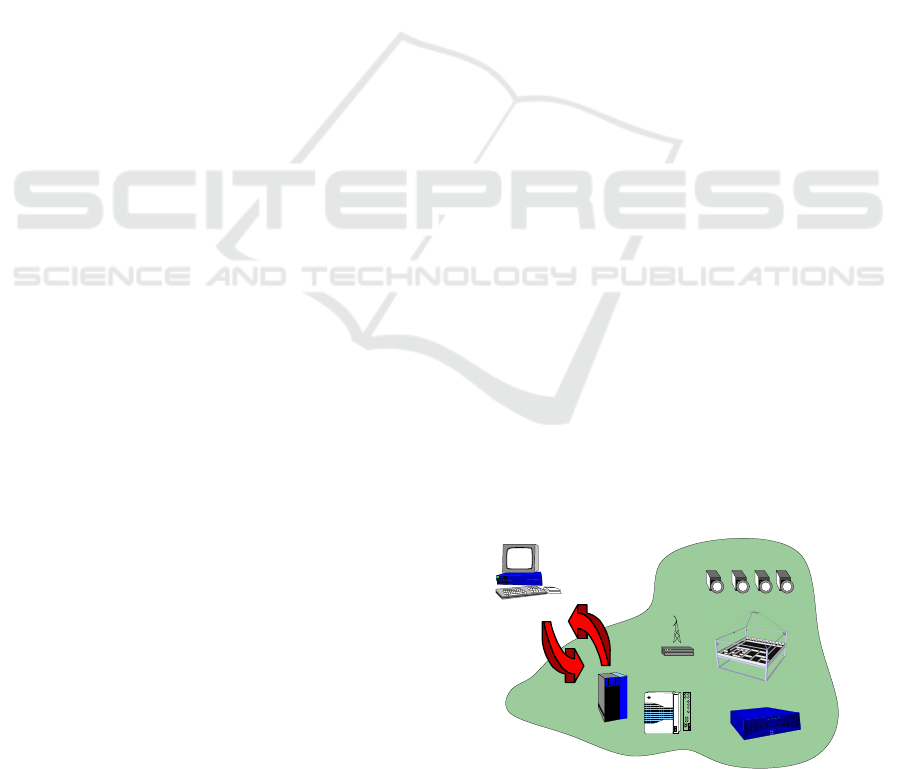
An overview of the SyRoTek realization is de-
picted in Fig. 1.
Localization of Robots
Robots in the Arena
User’s Workstation
Main Control
Computer
Video Server
WiFi
Visualization Cameras
SyRoTek
1
0
EMMI
Audio In
Audio Out
Video In1
Video In3
Video In2
Video Out
Figure 1: SyRoTek overview.
An user access to SyRoTek from his/her work-
station is realized through the main control computer
that is accessible from the Internet. A wireless com-
munication infrastructure is used to connect robots
with the main control computer. A visualization sys-
tem with several cameras provides views to the real
scene. A localization system based on a camera
placed above the arena is used to estimate real po-
sition of the robots.
412
Chudoba J., Faigl J., Kulich M., Krajník T., Košnar K. and P
ˇ
reu
ˇ
cil L..
A TECHNICAL SOLUTION OF A ROBOTIC E-LEARNING SYSTEM IN THE SYROTEK PROJECT.
DOI: 10.5220/0003341404120417
In Proceedings of the 3rd International Conference on Computer Supported Education (CSEDU-2011), pages 412-417
ISBN: 978-989-8425-49-2
Copyright
c
2011 SCITEPRESS (Science and Technology Publications, Lda.)

The paper is organized as follows. Identified re-
quirements steering the robot design are presented in
the next section. Detailed description of the robot
hardware is described in Section 3. The realization of
the arena with moving obstacles, robots’ docking sta-
tions and a global localization system are presented in
Section 4. A remote user access to the robots is real-
ized by the supporting computer that is directly acces-
sible through the Internet, its role and concept of the
user access to robots is briefly described in Section 5.
2 SYSTEM REQUIREMENTS
This section summarizes requirements affecting the
SyRoTek system design. At first, it is worth to men-
tion the system is designed as a multi-robotic, which
requires enough available robots for collective tasks.
Regarding to the expected scale of multi-robotic ex-
periments, we have decided to create a system with
10–15 robots.
The available space about 10 m
2
, restricts the
maximal robot diameter to 20 cm in order to pro-
vide sufficient work area. A differential drive with
two controlled wheels has been selected, offering suf-
ficient maneuverability in narrow space. The maxi-
mal robot velocity in range 0.2–0.5 m/s is considered
as sufficient.
The main goal of the SyRoTek system is to sup-
port education with real robots that will help students
to realize how robots sense the environment and how
to deal with uncertainties that are inevitable part of
real world. In order to provide such experiences, vari-
ety of sensors are requested to be mounted at the robot
body. The range-measuring sensors are the most typi-
cal sensors for basic robotic tasks. Also robot naviga-
tion based on image processing is becoming common
nowadays, so a color camera has been included in the
basic set of robot’s sensor equipment. Rotating laser
scanners (LIDARs) was selected as an optional equip-
ment for more advanced tasks.
The sensor equipment requires appropriate com-
putational resources that will allow simple sensory
data processing on-board. A PC-compatible com-
puter running operating system is highly desired for
such tasks, as it will allow a comfortable maintenance
and re-configuration.
Wireless communication device is needed on-
board for transmitting sensor data, control commands,
and software updates. IEEE 802.11 (WiFi) network
modules allow a wide bandwidth, but their disadvan-
tage is absence of the latency definition and eventual
drop-outs in noisy environments with many wireless
networks running alongside. This issue motivate us
to use another communication module to control the
robot, even at the cost of lower bandwidth.
The SyRoTek system is requested to run 24 hours
a day with a minimal maintenance that is mainly re-
lated to autonomous robots charging. A minimal run-
time for a charged robot is about two hours, which is
derived from the duration of regular course lab. Many
safety issues have to be solved as well, guaranteeing
any part of the system cannot be damaged as a result
of unexpected user action or internal failure.
3 ROBOTS
At the beginning of the SyRoTek project, several
available robotic platforms were discussed whether
they are applicable and meet identified requirements
of the project needs. Many robots were rejected due
to their size over 20 cm in diameter. Smaller robots
mostly did not meet desired sensor equipment or had
very poor options for extensions.
The most critical feature considered in the plat-
forms evaluation is mechanism of the robot charging.
All available robots considered are recharged with hu-
man attendance that would result in the need to adjust
robot for automatic recharge. Considering the amount
of necessary modifications of the considered robots in
combination with its price, we have decided to design
and manufacture a robot to serve our needs. The de-
veloped S1R robot is described in this section.
The most important component of the robot, influ-
encing its design, are batteries and motors. Lithium-
Polymer rechargeable cells were selected for the best
trade-off between capacity and size. Required opera-
tion time on batteries results in need of about 50 Wh
battery capacity. Monitoring of each cell individually
is necessary during the charging of the lithium based
battery, therefore a charger circuit has been embedded
into the robot body.
Two Faulhaber 2224 motors with integrated gear-
box and IRC encoder have been selected to meet the
required differential kinematics. Two driven wheels
are mounted directly to the motor gearbox axes. Outer
casing of the chassis is a bumper of octagonal shape
with rounded corners, as shown in Fig. 2.
On the top of the chassis, electronic modules are
mounted. Three main electronic boards are
• power control and charger board (power board),
• motor control and sensor data acquisition board
(control board) and
• on-board computer interface board with on-board
computer (OBC) mounted on.
A TECHNICAL SOLUTION OF A ROBOTIC E-LEARNING SYSTEM IN THE SYROTEK PROJECT
413
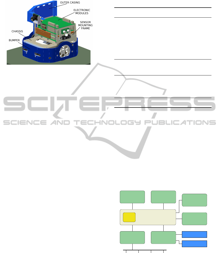
Figure 2: Main parts of the S1R robot.
A space in front of the robot is available for a re-
placeable sensor module (front module).
The top of the robot is covered by a lid with a
unique pattern used for robot localization and identi-
fication.
3.1 Sensor Equipment
Robot sensor equipment is summarized in the Table 1.
The encoders together with designed wheels with
radius 70 mm provide odometry information with res-
olution about 200 units per 1 millimeter of distance
traveled. Actual motor currents are monitored and
used for a simple collision detection if the robot is
stucked and the motor current is increased.
The exteroceptive sensors include two infrared
sensors directing forwards, mounted on chassis,
and three additional sensors mounted on the sensor
mounting frame. The additional sensors are directing
to left, right and backwards. Above the left, right and
rear infrared sensors, three sonars are mounted with
the same directions.
A commonly equipped front module consists of
three infrared sensors and three sonars, directing front
and 45
◦
left and right. Two floor sensors, each con-
taining four reflectivity detectors, are mounted on the
bottom of the robot.
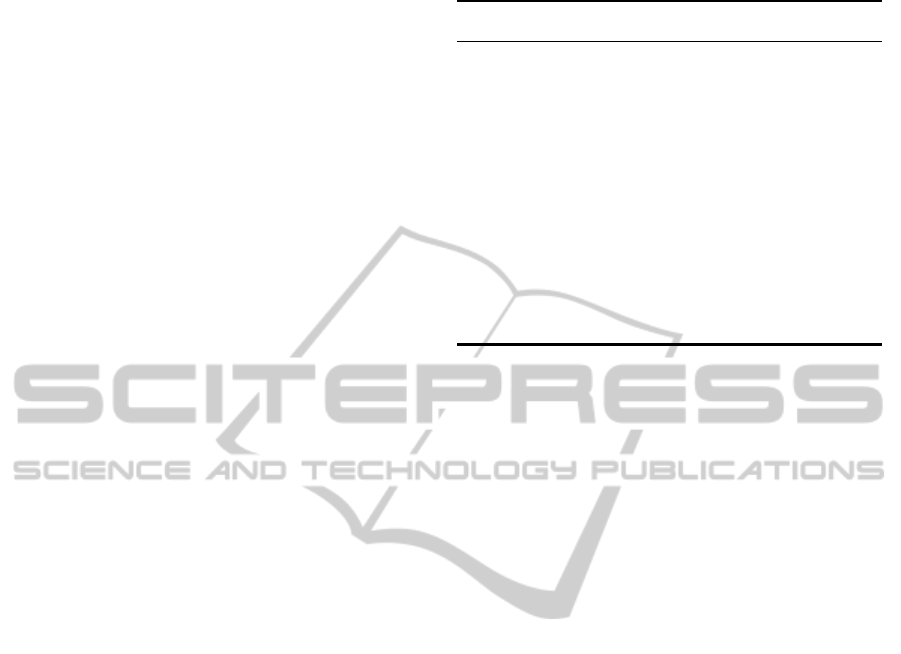
3.2 Electronic Modules
Each electronic component is connected to the on-
board computer (OBC) that provides the main access
to the robot through wireless communication chan-
nels as shown in Fig. 3.
The power module provides battery maintenance
and generation of on-board voltages. Embedded bat-
tery charger is able to charge the robot Li-Pol battery,
when an external voltage is present. Voltage of each
cell and the battery pack temperature is monitored
permanently to avoid dangerous states and possible
Table 1: Robot sensors.
Sensor Type
Chassis sensors:
IR range sensors 5× Sharp GP2D120
Sonars 3× Devantech SRF10
Compass Devantech CMPS03
Accelerometer Freescale MMA7260Q
Camera CmuCam3
Other sensors:
Floor sensor 2× 6-detector lines
Front sensor:
IR range sensors 3× Sharp GP2Y0A21Y
Sonars 3× Devantech SRF10
Laser rangefinder: Hokuyo URG-04LX
destruction of the pack.
The main function of the control board is to con-
trol robot motors and collect data from the chassis
sensors. It is based on the Hitachi H8S/2639 micro-
controller with embedded hardware counters for the
quadratic encoders. This processor provides odome-
try based estimation of the robot position within its
local coordinate frame.
The OBC (Gumstix Overo Fire with OMAP 3530
at 600 MHz) represents the main computational
power of the robot. Beside UART, SPI, I
2
C, and
USB communication interfaces, it provides on-board
802.11g wireless network module.
WiFi
sensor bus devices
OBC
UART
UART
SPI
UART
motors
sensors
bridge
radio
module
console
port
camera
module
laser
rangefinder
UART
USB
cMCU
(control board)
sensor bus
Figure 3: OBC connections to modules.
The radio module, dedicated to transmit real-time
control commands and low-data-rate sensor data be-
tween the robot and an external control computer, is
based on the Nordic nRF24L01 chip, allowing full-
duplex communication at speed over 100 kbps.
CSEDU 2011 - 3rd International Conference on Computer Supported Education
414
3.3 Inter-module Communication
Having several modules and variety of used sensors,
a unified approach to connect as much sensors as pos-
sible has been highly desirable. The I
2
C bus has been
selected as the primary communication bus between
the most electronics modules. We created so called
sensor bus by adding 2 lines to the standard I
2
C, al-
lowing module reset and firmaware update. The uni-
fied communication protocol simplifyes module im-
plementation.
A sensor bus communication protocol is
datagram-based and it basically follows com-
mon I
2
C communication based protocols. A fixed
length datagram header that may be eventually
followed by a variable size data message is used.
A publisher/subscriber schema is also used for
sensors readings to avoid polling based on the
request/response schema.
A microcontroller of each sensor-bus compliant
module has a boot-loader code implemented, allow-
ing remote firmware update over the sensor bus. This
feature has proven to significantly speed up develop-
ment process.
3.4 Power Consumption
As we require maximal operating time while robot
is powered from batteries, minimization of the power
consumption of individual components is crucial.
An average consumption of the motors is consid-
ered under 500 mW. The most power consuming com-
ponent is the OBC module, with consumption about
2 watts with the WiFi module running. The con-
sumption of most remaining electronic components
is about 10–40 mA at 5 V per processor or module.
Total consumption of all these devices and sensors is
between 2–3 watts in full operation mode. The total
power consumption of all these components is com-
parable to the consumption of OBC, so proper power
management is advisable, considering that all devices
are not necessary to run all the time.
When a laser rangefinder front module is used,
the power consumption rise significantly, by approx-
imately 3 watts, resulting in operation time drop by
30–50%.
Overall parameters of the robot are summarized
in Table 2. The robot operation time has been exper-
imentaly measured when the robot was performing a
IR-sensor based obstacle avoidance.
Table 2: Robot parameters.
Robot parameter Value
Length × Width × Height 174 × 163 × 180 mm
Weigth about 2 kg
Maximal velocity 0.34 m/s
Odometry resolution 200 samples/mm
Battery type Li-Pol (6 cells)
Battery voltage (nominal) 22.2 V
Battery capacity 2400 mAh (53 Wh)
Total power consumption about 5 Watts
Robot operation time about 8 hours
Robot charging current 2 A
Computation power ARM CPU @ 600 MHz
4 ARENA
The SyRoTek arena (see Fig. 4) is an enclosed space
dedicated for robots.
The robot working space is a flat area of dimen-
sion 3.5 m × 3.8 m with an outer barrier 18 cm tall.
Additional 13 cm tall obstacles are placed inside (see
Fig. 5). Some obstacles can be remotely retracted,
while the rest of them is fixed, however all obstacles
can be manually removed.
4.1 Robot Charging Docks
For each robot in the arena a dedicated docking space
is allocated, where a recharging mechanism is avail-
able. A space of docks is separated from the working
space and robots are exclusively controlled automati-
cally in this part of arena.
Several technical solutions of charging connec-
tor were discussed during the system design phase,
with respect to contact resistance, durability and
maintenance-free. Among other solutions a wireless
power transfer was tested and rejected mainly due to
necessity of very precise docking.
The final solution uses two flexible contacts (see
Fig. 6), pushed by springs against gilded metal pads
on the bottom of the robot. Two contact pads on each
contact are used to measure the contact resistance.
Each dock provides 2-Ampere power supply, allow-
ing the robot to fully recharge in about 1–2 hours.
4.2 Reconfigurable Obstacles
The arena was designed to be reconfigurable without
need of human attendance. This feature was achieved
A TECHNICAL SOLUTION OF A ROBOTIC E-LEARNING SYSTEM IN THE SYROTEK PROJECT
415
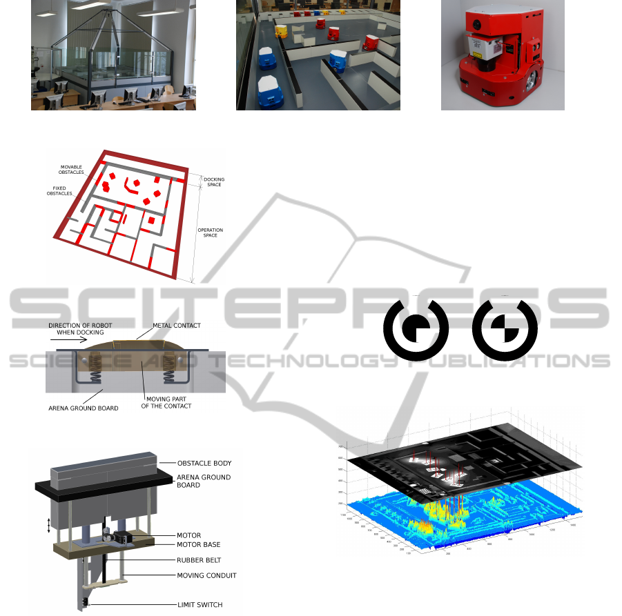
Figure 4: The SyRoTek arena and robots.
Figure 5: Obstacle configuration in arena.
Figure 6: Charging contact detail, side view.
Figure 7: A moving obstacle design.
by installing several moving obstacles, allowed to be
retracted under the surface, which is schematically
shown in Fig. 7. When a mechanism of moving obsta-
cles was designed, an operation noise and budget lim-
itations were the main criteria. As a noise generated
by the moving obstacles is nonneglible, frequency of
the arena reconfiguration should be minimized.
4.3 Robot Localization
A robot identity together with its position and orienta-
tion is estimated using an image processing method.
A grayscale camera (Unibrain Fire-i 820b) mounted
above the arena working space provides an image in
which patterns on the top of robots (an example is
shown in Fig. 8) are recognized. The graph in the
Figure 9 shows a result of a convolution-based lo-
calization function on a sample image. It is obvi-
ous that function maxima representing robot positions
are very distinctive, alowing robust localization under
various light conditions. An achieved accuracy of the
localization is about 3 mm in position estimation and
5
◦
in robot orientation.
Figure 8: An example of robot identification/localization
patterns.
Figure 9: Result of a robot localization algorithm.
5 USER ACCESS
The user access to SyRoTek is realized through con-
trol computer accessible from the Internet. It consists
of web pages with information about system, courses
and supporting materials, and an user application con-
trolling robot, running at the control computer.
Well-known and widely used the Player frame-
work (Gerkey et al., 2003; Player, 2010) has been
selected as the main user application interface. Al-
though the Player provides a flexible interface to con-
trol mobile robots, it does not support user authoriza-
tion to particular sensors. In an e-learning system, the
authorization is mandatory because in a certain task,
particular sensor is not allowed to be used by the user.
It is the main reason why a robot access module called
robacem was developed, representing a robot at the
CSEDU 2011 - 3rd International Conference on Computer Supported Education
416
control computer. The player server connects to the
robacem using specific player driver called syrdriv.
Particular options of the user’s application access
to the robot are shown in Fig. 10.
robacem
local
TCP
local IPC
player
control computer
user’s
application
onboard computer
robacem
local IPC
user’s
application
WiFi
TCP
Internet
application
RF
WiFi
player
local
TCP
user’s
workstation
user’s
hardware
robot
Figure 10: User’s application access to robot.
The player server provides an abstract layer hid-
ing particular hardware details. Moreover, the Stage
simulator (Vaughan, 2008) may be used, allowing ap-
plication development without real hardware.
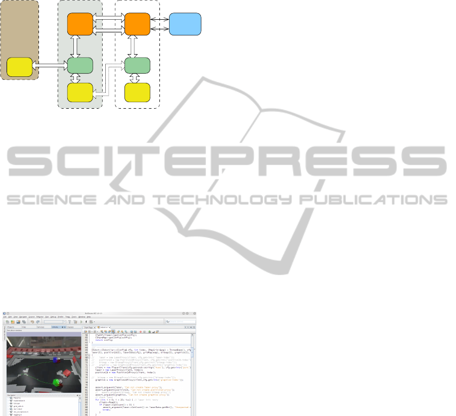
In SyRoTek, a dedicated visualization component
is being developed to provide a visualization tool. The
component is based on modified Stage simulator (ver-
sion 3.x) that is enhanced to support showing video
streams on-line or from recorded files. It can be used
as an independent visualization application or as a
plug-in for some of Integrated Developing Environ-
ment, e.g. Netbeans , see Fig. 11. The application al-
lows on-line visualization using current sensory data
transmitted from the SyRoTek control computer and
live streams from visualization cameras.
Figure 11: The SyRoTek visualization component within
the integrated developement environment.
6 CONCLUSIONS
The development of the SyRoTek project is still in
progress. However, the prototypes of educational
robotic platform S1R were already tested and robots
are now manufactured. Several experiments with col-
laborating robots in the arena have been performed
to verify the concepts and to test a developed hard-
ware and firmware. An other important part of the Sy-
RoTek project consists of web pages with supporting
materials and courses, guiding students (users) how
to use the system and how to create an application to
control a real mobile robot. Even though this part is
still under development, it is expected that a trial ap-
plication of SyRoTek will be opened for users from
July 2011.
ACKNOWLEDGEMENTS
The work presented in this paper has been supported
by the Ministry of Education of the Czech Republic
under program ”National research program II” by the
project 2C06005. Also, the support of the Ministry of
Education of the Czech Republic under the Project
No. 1M0567 to Jan Chudoba and Karel Ko
ˇ
snar is
gratefully acknowledged.
REFERENCES
Faigl, J., Chudoba, J., Ko
ˇ
snar, K., Saska, M., Kulich, M.,
Saska, M., and P
ˇ
reu
ˇ
cil, L. (2010). SyRoTek - A
Robotic System for Education. AT&P journal, 2:31–
36.
Gerkey, B. P., Vaughan, R. T., and Howard, A. (2003). The
player/stage project: Tools for multi-robot and dis-
tributed sensor systems. In Proceedings of the 11th In-
ternational Conference on Advanced Robotics, pages
317–323.
Guimar
˜
aes, E., Maffeis, A., Pereira, J., and et. al (2003).
Real: A virtual laboratory for mobile robot experi-
ments. IEEE Transaction on Education, 46(1).
Kulich, M., Faigl, J., Ko
ˇ
snar, K., P
ˇ
reu
ˇ
cil, L., and Chu-
doba, J. (2009). SyRoTek - On an e-Learning Sys-
tem for Mobile Robotics and Artificial Intelligence.
In ICAART 2009, volume 1, pages 275–280, Set
´
ubal.
INSTICC Press.
Mas
´
ar, I., Bischoff, A., and Gerke, M. (2004). Remote
experimentation in distance education for control en-
gineers. In Proceedings of Virtual University 2004,
Bratislava, Slovakia, pages 16–17.
Player (accessed 27 July 2010). http://playerstage.sf.net.
RedRover (accessed 26 September 2006). http://
www.redrover.reading.ac.uk/RedRover/.
Siegwart, R. and Sauc, P. (May 1999). Interacting mo-
bile robots on the web. In Proceedings of the 1999
IEEE International Conference on Robotics and Au-
tomation.
Vaughan, R. (2008). Massively multi-robot simulation in
stage. Swarm Intelligence, 2(2):189–208.
A TECHNICAL SOLUTION OF A ROBOTIC E-LEARNING SYSTEM IN THE SYROTEK PROJECT
417
