
USER-GUIDED FEATURE SENSITIVE HOLE FILLING
FOR 3D MESHES
Hanh T.-M. Ngo and Won-Sook Lee
School of Information Technology and Engineeing, University of Ottawa, Ontario, Canada
Keywords: Hole filling, Surface reconstruction, 3D modelling, Real time user interaction.
Abstract: Most hole filling approaches use techniques to fill up a hole first and then to smooth it. Very few tries
rebuild features on the filled surface of the original 3D model. We propose an efficient hole-filling
methodology which preserves sharp features of the geometry of the original model. The main idea is that we
reconstruct feature curves in the missing parts of the given mesh before filling the hole with smoothing
surface. The feature curves in the missing part are reconstructed by extending salient features of the
existing parts. The hole is partitioned into several smaller and more planar sub-holes divided by the feature
curves and then the hole-filling step follows. User intervention is available to design the features to be
desired shape to guide feature curve reconstruction wherever ambiguity exists or results are unsatisfactory.
Our hole filling techniques is different from other existing techniques as features are taken as the first
subject to reconstruct, which eventually drive the feature-definite surface filling process. It is also very
efficient as a user is interfering only with features and the actual hole-filling step is dealing with only planar
holes.
1 INTRODUCTION
3D computer models of real life objects can be
obtained by several ways such as 3D scanning
devices, or computer-aided design software
(Autodesk Maya, 3DS Max, etc.). A common
scenario, especially when dealing with 3D shapes
obtained from 3D scanning, is to have incomplete
surfaces. These appear in areas where the object
geometry occludes the scanning device, notable
examples when scanning human bodies include the
area under the chin, armpits or between the fingers,
hence limiting the information obtained. Because of
these issues, many post processing techniques are
needed to be applied onto the raw models before
being able to use them as the input of design or
animation applications. The repair of incomplete
polygon meshes is a fundamental problem in the
reconstruction of 3D models in the field of computer
graphics.
One of key aspects of reconstruction of 3D
models is hole-filling. This is to complete the shape
of the 3D object where surface information is
missing. This is essential for a wide range of
applications such as computer animation, pattern
recognition, or character design. Hole-filling
techniques aim to keep the filled surface
continuously and smoothly fitted at the boundary of
the hole to conform to the shape of the original
model. Although there is a large body of research on
hole filling, very little attention has been devoted to
the problem of recovering fine features of the 3D
object, for instance the sharpness of the edge
geometry. Most research focuses on automatic
methods that require performing complex
optimization processes (Chui and Lai, 2000; Attene
et al., 2003; Liepa, 2003; Jun, 2005; Podolak and
Rusinkiewicz, 2005; Zhao et al., 2007; Chen and
Cheng, 2008). In many cases, although the models
obtained are hole-free, interpolation algorithms fail
to preserve fine details, ignoring sharp edges and
corner shapes.
Due to the complexity of the regions where holes
are generated, automatic model modification
methods may not give satisfactory results in dealing
with holes. Complex optimization frameworks are
computationally expensive. In addition, processing
large and complicated models is a time consuming
task. Despite of the great computational overhead,
fine features in models are not recovered. Since
there are potentially several possible results for the
surface recovery process, the user should have the
49
T.-M. Ngo H. and Lee W..
USER-GUIDED FEATURE SENSITIVE HOLE FILLING FOR 3D MESHES.
DOI: 10.5220/0003324700490058
In Proceedings of the International Conference on Computer Graphics Theory and Applications (GRAPP-2011), pages 49-58
ISBN: 978-989-8425-45-4
Copyright
c
2011 SCITEPRESS (Science and Technology Publications, Lda.)

ability to influence the quality of the output surface.
Furthermore, although there are ways to set the
constraints for automatic methods to resolve
ambiguous topology problem, there will always be
the cases that require high-level knowledge to
disambiguate or have multiple answers, where the
selection depends on user’s preference. We believe a
program interface that allows user intervention
efficiently helps to reduce the implementation effort,
to give better visually plausible results and to
enhance the versatility of the system since the user
would have the ability to choose the desired feature-
topology and the shape of the filled mesh.
We are motivated by the need of a hole filling
system that is able to plausibly recover the fine
geometry features of the 3D models, especially the
sharp features, with some possible simple guidance
by users at the hole locations using a real time
Graphics User Interface (GUI). Our goal is to
develop a system that can repair the holes of the 3D
models and, at the same time, aesthetically preserve
the sharpness of the model at the hole locations with
the aid from user intervention.
Our main contributions are two-fold: (i) salient
features of the mesh geometry are taken as the first
subject to reconstruct, which eventually drive the
feature-definite surface filling process; (ii) the user
is allowed to influence the hole filling process at
feature designing level while the rest is taken care by
the automatic functions. Our results show missing
hole features are recovered with high quality while
supporting flexibility.
2 RELATED WORKS
Many researches on hole filling topic have been
done up to now. However, there are only few hole-
filling approaches attempting to preserve and to
recover the sharp features of the 3D model. In this
section we focus our discussion on feature sensitive
recovering methods for 3D meshes as they are of our
special interest.
Barequet and Kumar (Barequet and Kumar,
1997) proposed a method that allows users to inspect
the automatic results of the first iteration and also to
mark the areas to be corrected. The second iteration
produces the final results. The approach can produce
“intuitively-correct” filling of the holes with the aid
of the user.
In (Ohtake and Belyaey, 2003), to preserve the
shape of sharp edges and corners at the hole
locations, a multilevel piecewise surface fitting
method is employed to represent a mesh model that
has fine structures. Local approximation for fitting
edges and corners are based on the piecewise
quadric surface fitting method. It consists of a
number of tests (edge tests and corner tests) in order
to determine the type of approximation surface or
shape function that should be used. Edges and
corners are automatically recognized by clustering
the normals of the mesh vertices.
In (Sharf et al., 2004), a context-based
completion method is proposed to recover the
missing fine details in a repaired hole. The method
employs the idea of texture synthesis, by replicating
portions of regions from adequate examples. Based
on this idea, the fine structure of the 3D model is
recovered by finding a piece in the original model or
in the template models that is similar in shape to
replace the initial repaired hole. Hence, this method
is particularly efficient for repairing holes in
textured mesh model.
Attene et al. (Attene et al., 2003) proposed a
method to recover the sharp features of 3D mesh
model which are lost by reverse engineering or by
remeshing processes that use a non-adaptive
sampling of the original surface. The algorithm
starts by identifying the smooth edges in the mesh
model then applying the filters to get the chamfer
edges. Each chamfer edge and its incident triangles
are subdivided by inserting new vertices. These
vertices are calculated so that they lie on
intersections of planes that locally approximate the
smooth surfaces that meet at the sharp features.
In (Chen et al., 2005), holes are filled and
sharpness is recovered by applying a sharpness-
dependent filter. The filter operates based on the
distribution of the sharpness values of triangle faces
in the vicinity of a hole boundary. In this context,
the vicinity of a hole boundary is defined as its two-
ring neighborhood. For any triangle face, its
sharpness value is computed as the variance of the
angles between its normal and each of the normals
of the neighboring faces.
In (He and Chen, 2006), both automatic and
interactive methods are employed for hole-filling. A
novel hole-filling system that makes use of a haptic
device is proposed. After the hole identification
phase, the hole boundaries are smoothed in the
interpolation step. This step is to correct boundary
topologies and to adjust the boundary edge lengths
in order to avoid the uneven distribution of points at
the hole boundary. Then the user can decompose
those complex holes into simpler ones in stitching
process. Sub-holes are then automatically
triangulated using regular triangulation methods.
The user can repeat the intervention process until
GRAPP 2011 - International Conference on Computer Graphics Theory and Applications
50

obtaining satisfactory results. The authors proposed
an interesting idea about using haptic for 3D user
intervention. However, the limitation of this method
is the lack of an automatic method to detect the fine
features of the mesh to serve as the guidance for the
user.
In (Zhao et al., 2006), holes are detected then
triangulated using the modified minimum-weight
triangulation technique. Sharp features are recovered
by crest line fairing. The system makes use of the
crest line detection technique in (Yoshizawa et al.,
2005) to detect the feature lines in the original mesh.
Crest lines are the salient surface features defined
via the first- and the second-order curvature
derivatives. Detected crest lines are then used in
region growing and fairing processes to recover the
sharp features at the hole areas. The users are also
able to connect some crest lines before the region
growing step.
Chen and Cheng (Chen and Cheng, 2008)
presented a sharpness-based method for filling holes.
The whole algorithm performs in two steps: an
interpolation step for filling the hole which produces
the first approximation of the final model, and a
post-processing step which modifies the
approximation model to match the original. The
patch for the hole is interpolated using the radial
basis function to create a smooth implicit surface to
fill the holes. The implicit surface is triangulated
using a regularized matching tetrahedral algorithm.
Then the triangulated surface patch is stitched to the
hole boundary to obtain the repaired model. In the
post-processing step, a sharpness-dependent filter is
applied to the repaired model to recover its sharp
features. In this paper, the sharpness-dependent filter
is an improvement of the one presented in (Chen et
al., 2005). Although the algorithm works quite
effectively in repairing the models, the system is
difficult to implement.
Although an automatic system is always
desirable, dealing with fine features at the hole areas
is a challenging task. In spite of a complicated hole-
filling optimization engine to get the results
automatically as in (Zhao et al., 2007), the fine
features are not adequately recovered in many cases.
Most of the systems require user intervention
(Barequet and Kuma, 1997; He and Chen, 2006;
Zhao et al., 2006) to obtain the best guess of fine
features at the hole areas and to correct the
automatic results.
Our hole-filling system provides both fully
automatic and semi-automatic capabilities where
semi-automatic allows user to be comfortable
dealing with only several feature elements. If there is
no ambiguity in pairing the feature points and no
inaccurate crest lines detected at the hole vicinities,
our system can fully automatically produce
aesthetical results. Furthermore, while most hole
filling algorithms provide only automatic function
and manual hole filling takes a lot of user's time and
effort as it is at surface mesh level with numerous
points to touch and requires expert knowledge about
the objects and about how to manipulate on the 3D
mesh, our hole filling method, in the more complex
cases, need a very limited user intervention at the
feature level to support the hole filling procedure.
3 USER-GUIDED FEATURE
SENSITIVE HOLE FILLING
Our hole filling algorithm can completely fill the
holes of a model and aesthetically recover the
sharpness of the model at the hole areas, if any. It
includes the solution for efficient preservation of
sharpness properties of 3D mesh models during the
hole filling procedure; the solution for
implementation of a user-friendly interface to
support user intervention in real-time.
3.1 Algorithm Overview
Figure 1 shows a high level view of our user-guided
feature sensitive hole filling system. The input
model information is loaded into our designed data
structure for further usage in two modules: Crest
Incomplete model
Crest Line Detection Hole Identification
Feature pts Interpolation User Intervention
Feature Line Interpolation
Patch Generation
Patch Regulation
Repaired model
Figure 1: The framework of our system.
USER-GUIDED FEATURE SENSITIVE HOLE FILLING FOR 3D MESHES
51

Line Detection and Hole Identification. Crest line
information helps to find feature points in the holes
and their vicinities, which are used later for sharp
feature interpolation. Here, the user can interfere the
crest point positions and design the shape of the
patch mesh. Using this corrected information, our
system performs a feature line interpolation
procedure over the holes. This process defines the
expected fine features of the hole geometries and
also divides large complex holes into smaller and
more planar ones. For each of these simpler holes,
patch is generated by projecting the hole on its
projection plane, performing triangulation and then
mapping the triangulated topology back to 3D space.
The 3D patch is then stitched into the 3D model, and
it is regularized to make the patch consistent with
the original mesh, in order to produce the final
repaired mesh model.
3.2 Crest Line Detection
Defined in (Yoshizawa et al., 2005), the crest lines
are the salient surface features defined via the first-
and the second-order curvature derivatives. Crest
line detection has a significant role in our system
since it guides the user to pair the feature points on
the hole boundaries and to correctly interpolate the
feature lines over the holes. In our implementation,
we employed the crest line detection approach
proposed in (Yoshizawa et al., 2005).
Consider an oriented surface S and denote k
max
and k
min
its maximal and minimal principal
curvatures. Denote by t
max
and t
min
the corresponding
principal directions. Denote c
max
and c
min
the
derivatives of the principal curvatures along their
corresponding curvature directions. The convex crest
lines, also called ridges, are given by
c
max
= 0, δc
max
/δt
max
< 0,
k
max
> |k
min
|
(1)
while the concave crest lines, also called ravines, are
characterized by
c
min
= 0, δc
min
/δt
min
> 0,
k
min
< -|k
min
|
(2)
It also turns out that in our cases, the mesh
models are usually with holes, the crest lines that
suppose to pass over the holes areas are missing
after the crest line detection phase and need to be
recovered by some way. Furthermore, since there is
no surface information at the hole areas the detected
crest lines in the hole vicinity are usually go
incorrectly comparing to the case when the mesh
model is complete. In our algorithm, the detected
crest line information is used to interpolate the
missing parts. Hence, in order to have the accurate
interpolation results it is necessary to correct the
crest information at the hole vicinities first before
the interpolation is proceeded. We believe user
intervention to correct the crest line information is
the most efficient way and it is chosen in our
method. An example of inaccurately detected crest
lines at the hole’s vicinity and the corrected ones by
user through our GUI is showed in Figure 2.
Figure 2: (a) An example of inaccurate crest line detection
at the hole area: detected crest lines and crest points are
colored in green and blue correspondingly; (b) Crest lines
are corrected by user intervention.
3.3 Hole Identification
In the loading phase, all of the 1-ring neighbourhood
and connected component information of vertices,
edges and triangles of the input mesh model are
calculated and stored in our designed data structures
to facilitate further processing. Hence, at this step,
all boundary edges can be easily identified by
checking the numbers of their adjacent triangles, i.e.
for an edge, if the number of its adjacent triangles is
equal to one then that edge is a boundary edge. Its
two end vertices are the boundary vertices and its
adjacent triangle is the boundary triangle. Once the
boundary edge is detected, its two end vertices are
used as seeds to trace along the connected boundary
edges and vertices. If all identified points form a
closed loop they make up a hole.
3.4 Feature Line Interpolation
At this step, before doing the filling work, we
attempt to recover the sharp features, i.e. the feature
lines that suppose to pass over the hole areas. After
the feature lines are interpolated, the holes are also
subdivided by these feature lines into the smaller
and more planar ones. This indeed facilitates the
later hole filling procedure.
3.4.1 Basic Concepts
In our system convention, feature points are defined
GRAPP 2011 - International Conference on Computer Graphics Theory and Applications
52

as the crest points, either detected or interpolated,
that lie on the feature line segment passing over a
hole. Detected feature point is defined as the
intersection point between the crest line, either ridge
or ravine, with the hole boundary (see Figure 3).
Intersection point are the detected crest point, either
ridge- or ravine- point, that lies on hole edge, also
called boundary edge. Interpolated feature point is
the feature point obtained during the feature line
interpolation process. Figure 3 provides illustration
of these concepts.
Figure 3: An example of interpolating the feature lines
over a hole using spline interpolation: the interpolated
feature line is colored in blue, the interpolated feature
points are colored in green.
In the same way with Jun (Jun, 2005), we
consider two types of holes: simple hole and
complex hole. Simple holes are those that can be
filled with planar triangulations, which is the case
when all boundary edges can be projected into a
plane, without self-intersection (as illustrated in
Figure 4(a)). It is not adequate to fill the complex
hole with planar triangulations since there are
usually self-intersections when projecting the
complex hole boundaries into a plane (Figure 4(b)).
Thus, in our perspective, we attempt to properly
subdivide the complex holes into simple ones in
order to fill the holes by planar triangulation (see
Section 3.4.4).
Figure 4: Example of projecting holes onto planes: (a)
Simple hole makes no self-intersections; (b) Complex hole
creates self-intersections (colored in red) on the projection
plane.
3.4.2 User Intervention
Once feature points are detected in the previous step,
some limited user intervention at feature level is
needed
• To pair the detected feature points to avoid
ambiguity for the case there are multiple feature
lines passing over the hole;
• To adjust the inaccurately detected crest points
to enhance the accuracy and the quality of the
final result; and to specify the hole at the corner
of the object model by specifying the triple of
detected feature points lying on the hole
boundary at the corner area.
3.4.3 Feature Line Interpolation
To interpolate the missing feature lines passing over
the holes, the following issue should be addressed:
since we try to make use of the crest line
information which is automatically detected by the
system, the interpolated feature lines passing over
the hole should be interpolated by the available crest
lines and crest points.
We choose spline interpolation for interpolating
the feature lines at the hole areas. A spline is a
mathematical representation of a curve. It consists of
a series of points, called control points, at certain
intervals along the curve, and a function that allows
defining additional points within an interval.
Two requirements for the spline interpolation in
our case are
i. The curve should pass through all the control
points, as they define feature line, and its segments
act as the edges in the polygonal mesh model;
ii. It is necessary to be able to calculate the exact
positions of missing control points of the spline
based on the available ones.
There are various functions available for
approximating a curve and Catmull-Rom spline is
the one that satisfy the above requirements.
P
0
P
1
P
2
P
3
Figure 5: The Catmull-Rom spline passes through all of its
control points.
Recall the properties of Catmull-Rom spline
interpolation, a new point can be found between two
control points. This point is specified by a value t
USER-GUIDED FEATURE SENSITIVE HOLE FILLING FOR 3D MESHES
53

that represents a proportion of the distance from one
control point to the next one, as shown in Figure 5.
Given the control points P
0
, P
1
, P
2
, P
3
and parameter
t, 0≤ t ≤1.0, we can compute the new point location
q using the following equation:
0
1
23
2
3
0200
10 1 0
() 0.5 (1.0,, , )
2541
13 31
P
P
qt tt t
P
P
⎛⎞
⎛⎞
⎜⎟
⎜⎟
−
⎜⎟
⎜⎟
=∗ ∗ ∗
⎜⎟
⎜⎟
−−
⎜⎟
⎜⎟
−−
⎝⎠
⎝⎠
(3)
Figure 3 illustrates our method to interpolate a
feature line passing over a hole using the detected
crest line information. In our implementation, to
interpolate a feature line passing over a hole, the pair
of feature points on the hole boundary and their
adjacent crest points make four initial control points
for the Catmull-Rom interpolation equation (3).
Since we attempt to interpolate a feature line that has
the point density as consistent as possible to the
original mesh, the value t that appears in equation
(3) is approximated in our implementation as follow:
Given a hole that has n edges on its boundary.
Denote length(e
i
) the length of boundary edge e
i
;
denote a the average edge length of the hole
boundary. We have
n
a
n
i
i
elength
∑
=
=
1
)
(
(4)
Denote d the Euclidean distance between the
feature points F
1
and F
2
then we have
a
d
t =
(5)
3.4.4 Hole Partitioning
Once all the feature lines at the holes are
interpolated, a hole tracing procedure is executed.
For each hole, the procedure starts with a vertex on
the hole boundary, then it does the tracing along the
connected boundary edges and its corresponding
feature lines. If all identified points form a closed
loop they make up a hole. By involving feature lines
in the hole identification process at this step, the
original complex holes are indeed subdivided into
smaller, more planar and simpler sub-holes right at
the feature line locations.
In (Jun, 2005), the author discusses the self-
intersection problem when projecting a complex
hole onto a plane. This means some edges on the
hole boundary may overlap each other in the
projection plane. In our system, since the holes are
split at the salient feature curves, the sub-holes
obtained are already quite planar. In addition, by
using of the tangent plane of the hole boundary as its
projection plane our approach avoids efficiently the
self-intersection of the hole boundary.
3.5 Hole Filling
After all the polygonal holes in the original mesh
model are identified, for each hole its boundary
edges are then projected onto a projection plane for
further triangulation.
3.5.1 Projection Plane Calculation
For each hole or sub-hole identified in the input
mesh, we need to calculate the plane to project its
boundary onto. The requirement for such a plane is
that the projection of the boundary edges of a
polygonal hole on it is a bounded domain and it
should limit the possibility of creating the problem
of self-intersecting of the projected boundary as
much as possible.
We use the method to calculate the projection
plane that is based on the maximum area vector
method. The direction of the plane is derived from
the normalized sum of the normals of the boundary
triangles. The illustration of a hole and the direction
of its projection plane are shown in Figure 6. The
formula for computing the normal N of the
projection plane P for a hole is as follow:
∑
=
=
v
i
i
n
N
1
(6)
where v is the number of the boundary triangles of
the hole, n
i
is the normal of the i
th
boundary triangle
of the hole.
Figure 6: An example of a hole and the direction of its
projection plane.
GRAPP 2011 - International Conference on Computer Graphics Theory and Applications
54
3.5.2 Filling Holes through Planar
Triangulation
In our system, for each hole, once its boundary in
the original mesh model are projected onto its
corresponding projection plane, the projected
boundary vertices are used as the input for the
constrained Delaunay triangulation to get the patch
mesh for the hole in 2D. The procedure of mapping
back to 3D space of the patch mesh is done by
applying the topological structure of the constructed
2D triangulation to the original 3D boundary.
4 RESULTS AND VALIDATION
The visualization system Hole3D was developed as
the implementation to demonstrate our user-guided
feature sensitive hole filling system presented in this
paper. The visualization and user interface were
implemented in MS Visual Studio 2005
Development Environment with Coin3D (a high-
level 3D graphics toolkit for developing cross-
platform real-time 3D visualization and visual
simulation software), VTK (the Visualization
Toolkit) and MFC (Microsoft® Foundation Classes).
The programming language used is C++.
(a)
(b)
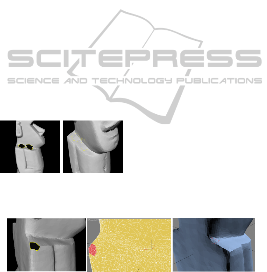
Figure 7: Applied our algorithm: (a) The input moai model
with two holes and concave sharp edges; (b) Hole filling
result obtained in our system with user intervention to pair
the feature points.
We demonstrate how the proposed algorithm can
be used to reconstruct hole regions. Basically, the
test cases are processed in two mesh models, the
moai model and the stripped fandisk model. Many
possible cases of hole are created and filled by our
system to verify its effectiveness.
Figure 7 shows the input moai model with two holes
and concave sharp edges at the neck area. The sharp
features are recovered properly using our method.
The patches stitched to the hole areas are marked
with the yellow boundary. Although we do not
implement mesh refinement and fairing techniques
in our system, the patch is adequate to complete the
model in expected way. Figure 12 shows the result
of filling a fandisk model with a concave corner hole
(Figure 12(a)). The final mesh model after applying
our feature sensitive hole filling algorithm are
displayed in Figure 12(b)(c).
As shown in Figure 9, with the hole at the convex
sharp edge, our system can achieve the proper
results. Figure 9(b) shows the hole filling result
obtained automatically by our system without a user
correcting the detected crest lines. Better result can
be obtained with user interaction to correct the
detected crest lines before interpolating feature lines
passing over the hole as shown in Figure 9(c).
We demonstrate the robustness of our system by
comparing our experiment results with the results
presented in papers (Chen et al., 2005; Zhao et al.,
2006). As shown in Figure 10, there are three holes
in fandisk mesh model, which has one, two and three
ridges passed through them (Figure 10(a)). As
presented in (Zhao et al., 2006), the method in
(Liepa, 2003) can only close the holes (Figure
10(b)), the method in (Zhao et al., 2006) produces
better result but the geometry at the corner hole is
not recovered properly (Figure 10(c)). Figure 11
demonstrates the hole filling results for convex and
concave corner holes obtained after applying the
sharpness dependent filter hole filling method in
(Chen et al., 2005).
(a) (b) (c)
Figure 8: Applied our algorithm: (a) The input moai model with a convex corner hole; (b) Our final hole filling result with
polygonal presentation, the hole patch is colored in red; (c) Flat shaded render of the final result.
USER-GUIDED FEATURE SENSITIVE HOLE FILLING FOR 3D MESHES
55
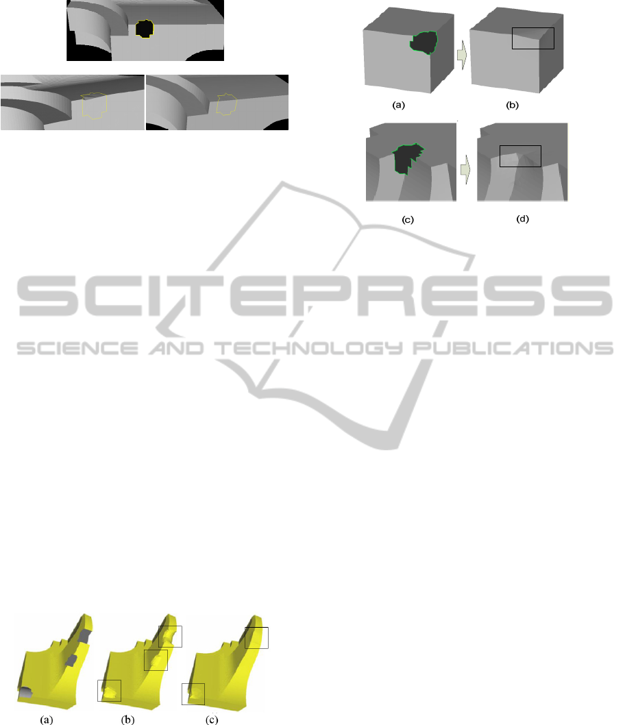
(a)
(b) (c)
Figure 9: Applied our algorithm: (a) The input stripped fan
disk model with a hole on the convex sharp edge; (b) Our
hole filling result without the user intervention to correct
the detected crest points at the hole area; (c) Our hole
filling result where the detected crest points are corrected
at the hole area.
To have a visual comparison with the
aforementioned algorithms, as shown in Figure 13,
we applied our hole filling method to the fandisk
model with holes at the same locations as in the
input mesh model in Figure 10 that reproduced from
(Zhao et al., 2006). Indeed, the modified mesh
model shows three typical kinds of holes that have
sharp features need to be recovered: one hole with
one feature line passing over, one hole with two
feature lines passing over and one hole at the corner.
The results of our hole filling technique are shown in
Figure 13: the sharp edges are recovered
aesthetically; the corner shape is reconstructed
consistently with the original shape. Figure 13(b)
shows the final hole filling result with the hole
highlighted in green. Figure 13(c) shows the hole
filling result obtained by our system, the patches are
stitched to the input mesh as the hole areas to get the
final mesh model. The sharp features at the concave
corner hole in Figure 12 are recovered nicely using
our method comparing to the result shown in Figure
11(b).
Figure 10: Applied the algorithms in (Liepa, 2003) and
(Zhao et al., 2006): (a) The input mesh model with 3
holes; (b) The result obtained by using method in (Liepa,
2003); (c) The result obtained by using method in (Zhao et
al., 2006) (reproduced from (Zhao et al., 2006)).
Figure 11: Applied the hole filling algorithm in (Chen et
al., 2005) to the holes at the corners: (a) A original mesh
model with a convex corner hole; (b) The result after
filling the hole in the model in (a); (c) A original mesh
model with a concave corner hole; (d) The result after
filling the hole in the model in (c) (reproduced from (Chen
et al., 2005)).
The experiments show that our method can
produce excellent results for filling the holes at the
corners. The mesh quality of the patches could be
improved to make them more consistent with the
original mesh quality by applying mesh refinement
techniques.
5 DISCUSSION
Certainly, fully automated methods for hole filling
have several advantages over a method that requires
user intervention. However, from the point of view
of the complexity of the hole, a fully automated
method may not work correctly for holes with
complex geometries. Our research aims to combine
manual and automatic methods to improve current
hole-filling methods, making this process more
versatile, robust and effective.
Most of the feature sensitive hole-filling methods
rely significantly on the normals of the vertices
around the hole areas to decide whether or not there
exist fine features. This makes those methods
sensitive to the mesh quality, e.g. the point density,
the shapes of triangles and the point distribution. In
our algorithm, since the feature curves are
interpolated from the salient information detected in
the mesh model, user intervention allows to correct
the detected crest line information. This enables the
whole algorithm to produce the final results quite
independently from the quality of the input mesh
GRAPP 2011 - International Conference on Computer Graphics Theory and Applications
56
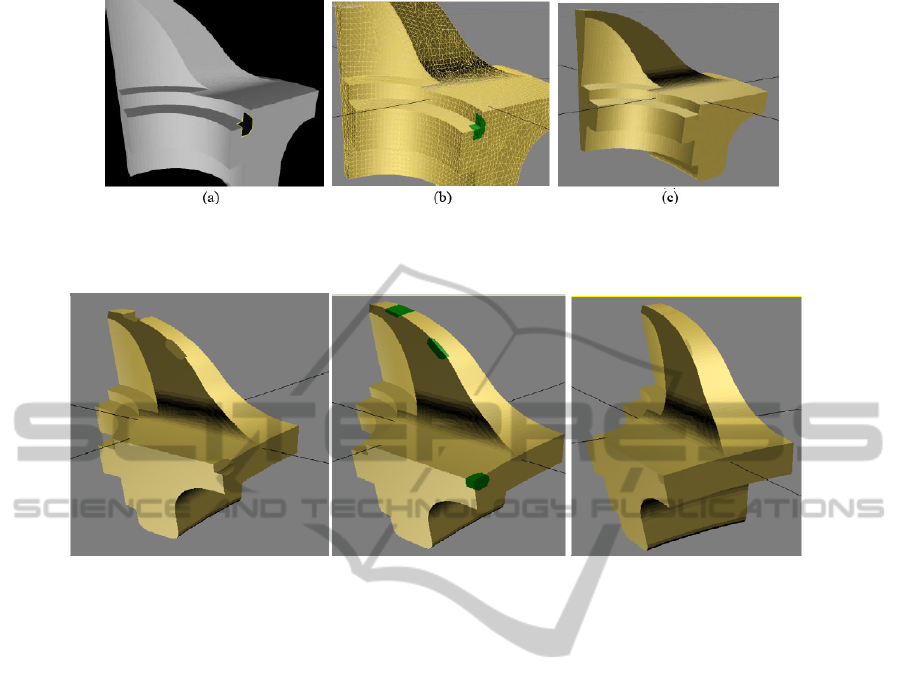
Figure 12: Our algorithm results: (a) The input stripped fandisk model with a concave corner hole; (b) Our final hole filling
result with polygonal presentation, the hole patch is colored in green; (d) Flat shaded render of the final result model.
(a) (b) (c)
Figure 13: Applied our algorithm to a moai model with 3 types of holes: (a) The original mesh model with 3 kinds of holes;
(b) The final result obtained by our system with the highlighted patches; (c) Flat shaded render of the final mesh result.
model.
The core idea of our algorithm using the salient
information to recover the sharp feature is simple
but effective. Among the existing techniques that
have attempted to reconstruct fine features of the
original mesh at the hole areas, our hole filling
techniques is different since the fine features are
taken as the first subjects to reconstruct, which
eventually drive the feature-definite surface filling
process. Our results show the effectiveness of our
method in filling the hole and preserving
aesthetically the sharp edges.
The accuracy of our method depends to a great
extent on the accuracy of the crest line detection
method. We expect that improvements in crest line
detection will produce a higher quality results from a
fully automatic procedure based on our approach. In
our implementation, all of the salient and polygonal-
based information of the input mesh model are
extracted and stored in our designed data structures
in the loading phase then further computation is
limited to areas near holes. This makes the algorithm
efficient to run on large models.
Our system improves the visual quality of the
results with respect to previous approaches and
provides real-time user interaction. On the other
hand, it strongly relies on crest line detection, and
therefore it is very sensitive to changes in this
geometrical feature. Our system is able to recover
efficiently the sharp features, especially when the
feature curves or the profile of the sharp edges are
close to the cubic splines. However, if the profile of
the sharp edges in the input mesh is more complex
than cubic splines, the results may not be necessarily
accurate and may even be far from the real
geometry.
Further mesh refinement and fairing methods
may be used to improve the quality of the generated
patch meshes. By doing this, the point density and
triangle shape in the patch mesh will be consistent
with the input mesh.
6 CONCLUSIONS
We have presented a novel technique for filling
holes in 3D triangulated mesh models which is able
to recover efficiently the sharp features of the
original geometry, producing plausible results which
are consistent with the geometry of the original
mesh models. For each input mesh, our system
identifies its hole and crest line information. Then it
USER-GUIDED FEATURE SENSITIVE HOLE FILLING FOR 3D MESHES
57

uses this information to geometrically segment
complex holes into simple approximately planar
holes, called sub-holes. The patch meshes that are
used to fill those sub-holes are generated by using
planar triangulation algorithm for the point set at the
hole boundaries. Then these patch meshes are
mapped back to the 3D space and stitched to the
original model at the hole areas to achieve the final
result. The user is able to interact with our system
through correcting the crest lines, adjusting the
feature points defined by the crest lines and the hole
boundaries, pairing the feature points or specifying
the corner hole locations. The adjustment of the
location of the crest lines by users results in
modification in the shape of the patch mesh which is
later stitched to the original model, as holes are
filled using different geometric information. To
validate our approach, we have tested our technique
on different mesh models with many possible cases,
and the results show that our methods effectively
reconstruct the sharp features. Most approaches for
hole filling in literature do not reconstruct these fine
details due to the interpolation schemes used. We
overcome this limitation by including additional
information on the object shape in areas of high
curvature and by limited user intervention.
REFERENCES
Attene, M., Falcidieno, B., Rossignac, J., Spagnuolo, M.,
2003. Edge-Sharpener: Recovering Sharp Features in
Triangulations of Non-adaptively Re-meshed
Surfaces. In Proceedings of the First Eurographics
Symposium Geometry Processing (SGP’03), pages 63-
72.
Barequet, G., Kumar, S., 1997. Repairing CAD Models. In
Proceedings of the 8th conference on Visualization
'97, pages 363-371, Phoenix, Arizona, USA.
Barequet, G., Dickerson, M., Eppstein, D., 1998. On
triangulating three-dimensional polygons.
Computational Geometry: Theory and Applications,
10(3) pages 155-170.
Chen, C.-Y., Cheng, K.-Y., 2008. A sharpness-dependent
filter for recovering sharp features in repaired 3D
mesh models. IEEE Transactions on Visualization and
Computer Graphics, volume 14, No. 1,
January/February 2008.
Chen, C.-Y., Cheng, K.-Y., Liao, H. Y. M., 2005. A
Sharpness Dependent Approach to 3D Polygon Mesh
Hole Filling. Eurographics, Short Presentations, 2005.
Chew, P. L., 1989. Guaranteed-Quality Triangular
Meshes. Technical report 89-983, Department of
Computer Science, Cornell University, Ithaca, NY,
April 1989.
Chui, C. K., Lai, M.-J., 2000. Filling Polygonal Holes
Using C
1
Cubic Triangular Spline Patches. Computer
Aided Geometric Design, volume 17(2000), pages
297-307.
Dunlop, R., 2005. Introduction to Catmull-Rom Splines.
Technical articles, Microsoft DirectX MVP. URL:
http://www.mvps.org/directx/articles/catmull/
He, X. J., Chen, Y. H., 2006. A Haptics-guided Hole-
filling System Based on Triangular Mesh. Computer
Aided Design and Application, volume 3(6), pages
711-718.
Jun, Y., 2005. A Piecewise Hole Filling Algorithm in
Reverse Engineering. Computer-Aided Design 37,
pages 263-270.
Kobbelt, L. P., Botsch, M., Schwanecke, U., Seidel, H.-P.,
2001. Feature Sensitive Surface Extraction from
Volume Data. In Proc. of ACM SIGGRAPH 2001,
pages 57–66.
Liepa, P., 2003. Filling holes in Meshes. In Proceedings of
the Eurographics/ACM SIGGRAPH symposium on
Geometry Processing 2003, Eurographics Association,
pages 200-205.
Ohtake, Y., Belyaev, A., Alexa, M., Turk, G., Seidel, H.-
P., 2003. Multi-level Partition of Unity Implicits. ACM
Trans. Graphics, Proc. ACM SIGGRAPH 2003,
volume 22(3), pages 463-470.
Podolak, P., Rusinkiewicz, S.2005. Atomic Volumes for
Mesh Completion. In Proceedings of Eurographics
Symposium on Geometry Processing, Dublin, Ireland,
29 August-2 September 2005, pages 33-41, Blackwell
Press 2005.
Sharf, A., Alexa, M., Cohen-Or, D., 2004. Context-based
Surface Completion. ACM Transactions on Graphics,
SIGGRAPH 04, 23, 3.
Yoshizawa, S., Belyaev, A.G., Seidel, H.-P., 2005. Fast
and Robust Detection of Crest Lines on Meshes. ACM
Symposium on Solid and Physical Modeling, pages
227-232, Technical Sketch, June 13-15, 2005, MIT,
Cambridge, MA.
Yoshizawa, S., Belyaev, A., Yokota, H., Seidel, H.-P.,
2007. Fast and Faithful Geometric Algorithm for
Detecting Crest Lines on Meshes. Pacific Graphics,
pages 231-237, October 29-November 2, 2007, Maui,
Hawaii.
Zhao, W., Gao, S., Lin, H., 2007. A Robust Hole-Filling
Algorithm for Triangular Mesh. Visual Computer 23,
pages 987-997.
Zhao, M., Ma, L., Mao, Z., Li, Z., 2006. Feature Sensitive
Hole Filling with Crest Lines. Lecture notes in
Computer Science. In Proc. of Advances in Natural
Computation. The Second International Conference on
Natural Computation, Xi’an, China.
GRAPP 2011 - International Conference on Computer Graphics Theory and Applications
58
