OUTDOOR ILLUMINATION ESTIMATION IN IMAGE SEQUENCES
FOR AUGMENTED REALITY
Claus B. Madsen and Brajesh B. Lal
Department of Architecture, Design & Media Technology, Aalborg University, Aalborg, Denmark
Keywords:
Illumination, Augmented Reality, Shadows, Stereo, HDR.
Abstract:
The paper presents a technique for estimating the radiance of the sky and sun for outdoor, daylight illumi-
nation conditions. Shadows cast by dynamic objects are detected using color imagery, combined with depth
information from a commercial stereo camera setup. Color information extracted from the detected shadows
is used to estimate the radiance of the sun. The technique does not require special purpose objects in the scene,
nor does it require High Dynamic Range imagery. Results are demonstrated by rendering augmented objects
into real images with shading and shadows which are consistent with the real scene.
1 INTRODUCTION
For photo-realistic Augmented Reality (AR) the goal
is to render virtual objects into real images to create
the visual illusion that the virtual objects are real. A
crucial element in achieving this illusion is to have
a sufficiently correct model of the illumination con-
ditions in the scene to be able to render the virtual
objects with scene consistent shading and to render
correct shadow interaction between real and virtual
geometry.
This paper presents an adaptive illumination es-
timation technique for outdoor daylight scenes. The
technique uses color image sequences, combined with
live stereo data, to estimate the radiance of a sky dome
(hemi-sphere) and the radiance of the sun. Both radi-
ances are estimated in three color channels. The po-
sition of the sun is computed procedurally from GPS
and date/time information. Together, this illumination
environment (sky dome and sun) can be used to render
virtual objects into the scene. As an additional benefit
the stereo information provides 3D scene information
to cast shadows on and to handle occlusion between
real and virtual objects. Figure 1 shows an example
result.
The main contribution in this work lie in the fact
that the illumination is estimated directly from the im-
age sequence with no need for special purpose ob-
jects in the scene, and no need for acquiring omni-
directional High Dynamic Range environment maps
(light probes) prior to augmentation.
The paper is organized as follows. Section 2
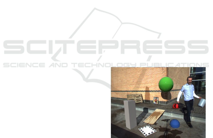
Figure 1: Frame 139 of a 200 frame sequence. The diffuse
grey box and the three glossy spheres are rendered into the
scene with illumination estimated from the shadow cast by
the walking person.
describes related work, and section 3 describes the
assumptions behind the presented work. Section 4
presents the theoretical framework for our approach,
both in terms of detecting shadows and in terms of
estimating scene illumination from detected shadows.
Sections 5 and 6 present the dynamic shadow detec-
tion and the illumination estimation, respectively. Ex-
perimental results are presented in section 7, followed
by discussions and ideas for future research in section
8. Finally, section 9 presents concluding remarks.
129
B. Madsen C. and B. Lal B..
OUTDOOR ILLUMINATION ESTIMATION IN IMAGE SEQUENCES FOR AUGMENTED REALITY.
DOI: 10.5220/0003321301290139
In Proceedings of the International Conference on Computer Graphics Theory and Applications (GRAPP-2011), pages 129-139
ISBN: 978-989-8425-45-4
Copyright
c
2011 SCITEPRESS (Science and Technology Publications, Lda.)

2 RELATED WORK
A survey of real scene illumination modelling for
Augmented Reality is given in (Jacobs and Loscos,
2004). The survey indicates that there is no one pre-
ferred or most popular family of approaches. No
technology has matured to the point of outperform-
ing other types of approaches. In fact, any approach
offers a set of possibilities at the price of a set of as-
sumptions or limitations, leaving the application sce-
nario to define which approach to choose.
There are three main categories of approaches:
1) omni-directional environment maps, 2) placing
known objects/probes in the scene, and 3) manually
or semi-manually model the entire scene, including
the light sources, and perform inverse rendering.
The most widely used approach is to capture the
scene illumination in a High Dynamic Range (HDR),
(Debevec and Malik, 1997), omni-directional envi-
ronment map, also called a light probe. The technique
was pioneered by Debevec in (Debevec, 1998) and
used in various forms by much research since then,
e.g., (Barsi et al., 2005; Debevec, 2002; Gibson et al.,
2003; Madsen and Laursen, 2007). The technique
gives excellent results if the dominant illumination in
the scene can be considered infinitely distant relative
to the size of the augmented objects. The drawbacks
are that it is time-consuming and impractical to ac-
quire the environment map whenever something has
changed in the scene, for example the illumination.
Illumination adaptive techniques based on the envi-
ronment map idea have been demonstrated in (Havran
et al., 2005; Kanbara and Yokoya, 2004) but require a
prototype omni-directional HDR camera, or a reflec-
tive sphere placed in the scene, respectively.
The other popular family of approaches is based
on requiring the presence of a known object in the
scene. Sato et al. analyze the shadows cast by a
known object, (Sato et al., 1999a; Sato et al., 1999b)
onto a homogeneous Lambertian surface, or require
images of the scene with and without the shadow cast-
ing probe object. Hara et al., (Hara et al., 2005) ana-
lyze the shading of a geometrically known object with
homogeneous (uniform albedo) Lambertian object, or
require multiple images with different polarizations,
to estimate the illumination direction of a single point
light source. Multiple light sources can be estimated
from the shading of a known object with homoge-
neous Lambertian reflectance using the technique de-
scribed in (Wang and Samaras, 2008).
The last family of approaches do not estimate il-
lumination per se as they rely on modelling the en-
tire scene in full detail, including modelling the ge-
ometry and the radiances of the light sources. The
modelling process is labor intensive. Given the full
description of the scene and images of it (in HDR if
needed) inverse rendering can be performed to esti-
mate the parameters of applicable reflectance func-
tions of scene surfaces. Subsequently virtual objects
can be rendered into the scene with full global illumi-
nation since all required information is known. Exam-
ples include (Boivin and Gagalowicz, 2001; Boivin
and Gagalowicz, 2002; Loscos et al., 2000; Yu et al.,
1999).
A final piece of related work does not fall into the
above categories, as it is the only representative of this
type of approach. Using manually identified essential
points (top and bottom point of two vertical structures
and their cast shadow in outdoor sunlight scenes) the
light source direction (the direction vector to the sun)
can be determined, (Cao et al., 2005).
In summary existing methods either require pre-
recorded full HDR environment maps, require homo-
geneous Lambertian objects to be present in the scene,
require total modelling of the scene including the il-
lumination, or require manual identification of essen-
tial object and shadow points. None of the mentioned
techniques offer a practical solution to automatically
adapt to the drastically changing illumination condi-
tions of outdoor scenes.
The approach proposed in this paper addresses
all of these assumption and/or constraints: it does
not require HDR environment maps, nor HDR image
data, it does not require objects with homogeneous
reflectance (entire objects with uniform reflectance),
it does not require manual modelling of the illumina-
tion (in fact the illumination is estimated directly) and
there is no manual identification of essential points.
3 ASSUMPTIONS BEHIND
APPROACH
Our approach rests on a few assumptions that are
listed here for easy overview. It is assumed that we
have registered color and depth data on a per pixel
level. High Dynamic Range color imagery is not re-
quired; standard 8 bit per color channel images suffice
if all relevant surfaces in the scene are reasonably ex-
posed. In this paper the image data is acquired using
a commercially available stereo camera, namely the
Bumblebee XB3 from Point Grey, (PointGrey, 2009).
It is also assumed that the response curve of the color
camera is approximately linear. The Bumblebee XB3
camera is by no means a high quality color imaging
camera but has performed well enough. It is also as-
sumed that the scene is dominated by approximately
diffuse surfaces, such as asphalt, concrete, or brick,
GRAPP 2011 - International Conference on Computer Graphics Theory and Applications
130

see figure 1 for an example. There is no homogeneity
assumption, and in section 8 we will briefly describe
ongoing/future work to relax the diffuse surface con-
straint.
To be able to procedurally compute the direction
vector to the sun we need to know the Earth location
in latitude/longitude (acquired from GPS), the date
and time of the image acquisition, and we assume that
the camera is calibrated (extrinsic parameters for po-
sition and orientation) to a scene coordinate system
with xy-plane parallel to a horizontal ground plane
(z-axis parallel to the direction of gravity), and x-axis
pointing North. The checkerboard in figure 1 is used
for camera calibration.
4 ILLUMINATION MODEL
The purpose of this section is to establish the theoret-
ical foundation for both the shadow detection and the
illumination estimation. All expressions in this pa-
per relating to pixel values, radiometric concepts, and
surface reflectance et cetera are color channel depen-
dent expressions and are to be evaluated separately for
each color channels.
If the response curve of the camera is linear the
pixel value in an image is proportional to the outgoing
radiance from the scene surface point imaged to that
pixel, (Dutr
´
e et al., 2003). The constant of proportion-
ality depends on things such as lens geometry, shutter
time, aperture, camera ISO setting, white balancing
settings, etc. If the unknown constant of proportion-
ality is termed c the value P of a pixel corresponding
to a point on a diffuse surface can be formulated as:
P = c · ρ · E
i
·
1
π
(1)
where ρ is the diffuse albedo of the surface point, and
E
i
is the incident irradiance on the point. ρ times E
i
yields the radiosity from the point, division by π gives
the radiance, and c is the camera constant mapping
radiance to pixel value. For a point in sunlight the in-
cident irradiance, E
i
, is the sum of irradiance received
from the sun and from the sky, provided that we can
disregard indirect Global Illumination from other sur-
faces in the scene, (for a discussion on this please re-
fer to section 8).
The irradiance received from the sun can be for-
mulated as:
E
sun
= ~n ·
~
s · E
⊥
s
(2)
where ~n is the unit surface normal at the point,
~
s is
the unit direction vector to the sun (both relative to
the scene coordinate system) and E
⊥
s
is the irradiance
produced by the sun on a point with a normal pointing
straight into the sun. The direction vector to the sun
is computed procedurally from the GPS and date/time
information using the approach described in (Blanco-
Muriel et al., 2001).
The irradiance from the sky can be formulated as:
E
sky
= V
a
· E
⊥
a
(3)
where V
a
is the fraction of the sky dome which is visi-
ble from the surface point, and E
⊥
a
(subscipt a for “at-
mosphere” or “ambient”) is the irradiance produced
by the sky dome on surface point with normal point-
ing straight into the sky dome and receiving light from
the entire dome. In our experiments the visibility frac-
tion V
a
is computed on a per point basis using the
scene geometry provided by the stereo camera, see
section 6.
The illumination model in this work consists of a
hemi-spherical sky dome of uniform radiance, and a
sun disk. The diameter of the sun disk as viewed from
earth is 0.53 degrees, (Dutr
´
e et al., 2003). The tech-
nique for estimating the irradiances (and hence the ra-
diances) of the sky and the sun directly from image
measurements represents the main contribution of this
paper. Our approach is in two steps: 1) detection of
dynamic shadows (cast by moving objects), and 2) us-
ing chromatic information from the detected shadows
to compute the radiance of the sky dome and the sun,
respectively.
Figure 2: Textured 3D scene mesh generated from stereo
disparity information from the image shown in figure 1.
Notice how well the main surfaces in the scene are recon-
structed.
5 SHADOW DETECTION
Existing work on single image shadow detection does
not really handle soft shadows, or requires manual
training. Example work includes (Nielsen and Mad-
sen, 2007; Finlayson et al., 2002; Salvador et al.,
OUTDOOR ILLUMINATION ESTIMATION IN IMAGE SEQUENCES FOR AUGMENTED REALITY
131

2004). Existing work on dynamic shadow detection
from image sequences either rely on a simplistic il-
lumination model (the grey world assumption which
is definitely not valid in outdoor scenes), or require
a high quality trained background model. Example
work includes (Huerta et al., 2009; Horprasert et al.,
1999; Kim et al., 2005; Chalidabhongse et al., 2003),
and a survey can be found in (Prati et al., 2003).
For this work we have developed a dynamic
shadow detection technique which does not rely on a
trained background model and utilizes the available
depth information. Figure 2 shows an example of
the 3D data provided by the Bumblebee camera (and
the accompanying API). In this section we briefly de-
scribe the approach. For more detail and additional
experimental results, please refer to (Madsen et al.,
2009).
The shadow detection technique is based on image
differencing. A delayed frame (from time t − ∆t) is
substracted from the current frame (from time t) both
for color images and for stereo disparity images. If,
for a given pixel, the color image difference is nega-
tive in all three color channels (less light emited from
the point at time t than at time t − ∆t), and the dispar-
ity difference is zero (no change in depth), the pixel is
classified as a shadow candidate. If there is a change
in depth it is not a potential shadow candidate but
rather a pixel belonging to a moving object.
Choosing the length of the frame delay ∆t is not
critical. If set high (long delay) we achieve better abil-
ity to detect the whole shadow since the shadows cast
in the two frames are less likely to overlap. On the
other hand a long frame delay makes the system less
responsive to changes in the illumination conditions.
In the experiments reported here we have used a frame
delay of 0.5 seconds (the Bumblebee camera delivers
color and disparity images at a frame rate of 10 fps in
640x480 pixel resolution).
Figure 3 show the detected shadow candidates
corresponding to the image in figure 1. Here we have
used a ∆t of 10 seconds to give a better visual impres-
sion of detected shadows. Water poured onto surfaces
by the test person (to simulate rain) are also initially
classified as shadow candidates.
Further analysis of the shadow candidates is per-
formed in log chromaticity space. In log chromaticity
space, combining with the general pixel value expres-
sion from eq. (1), we get two chromaticity values per
pixel, r and b (using superscripts r/g/b to indicate
RGB color channel specific value):
r = log(P
r
/P
g
)
= log(P
r
) −log(P
g
)
= log(c
r
) − log(c
g
) + log(ρ
r
) − log(ρ
g
) +
log(E
r
i
) − log(E
g
i
) (4)
Figure 3: Top: shadow candidate pixels in frame 139. Bot-
tom: verified shadow pixels after chromaticity analysis. No-
tice that water splashes are not classified as shadow pixels
demonstrating robustness to rain.
b = log(P
b
/P
g
)
= log(c
b
) − log(c
g
) + log(ρ
b
) − log(ρ
g
) +
log(E
b
i
) − log(E
g
i
) (5)
If a pixel has been marked as shadow candidate it
means we have two versions of the same pixel, one
from time t and one from time t − ∆t. The color
channel values have changed for that pixel, which in
turn means that the pixel’s location in log chromatic-
ity space has moved. Basically two things can have
caused this: 1) sunlight at the surface point corre-
sponding to the pixel was blocked (shadow), or 2)
the surface changed albedo, e.g., became wet. Study-
ing the displacements in chromaticity space forms
the basis for the final classification of shadow pix-
els. This approach is inspired by (Marchand and
Onyango, 2000).
We assume that the camera constants c
r/g/b
did
not change during ∆t. If we hypothesize that the sur-
face albedos ρ
r/g/b
did not change:
∆r = r(t) − r(t − ∆t)
= log
E
r
i
(t)
E
r
i
(t − ∆t)
− log
E
g
i
(t)
E
g
i
(t − ∆t)
(6)
GRAPP 2011 - International Conference on Computer Graphics Theory and Applications
132

Figure 4: Left: per pixel normal map encoded as RGB val-
ues for the image in figure 1. Right: per pixel sky dome
visibility in the range 0 to 1.
∆b = log
E
b
i
(t)
E
b
i
(t − ∆t)
!
− log
E
g
i
(t)
E
g
i
(t − ∆t)
(7)
Thus, log chromaticity displacements of shadow
candidate pixels depend only on the change in inci-
dent irradiances, namely the various E
i
values (which
are of course unknown). This means that all shadow
pixels should exhibit displacements that are parallel
in log chromaticity space. If a pixel does not displace
in the same direction it must be because the albedo
changed (the constant albedo hypothesis is false and
eqs. 6 and 7 do not hold), e.g., the surface point
became wet, or it otherwise changed color. This is
utilized by selecting only the pixels whose displace-
ment orientation (computed as θ = arctan(∆b/∆r)) is
within a certain threshold of +90 degrees (a displace-
ment towards blue). We have used a threshold of 20
degrees. A shift towards blue is what is expected from
a surface point transitioning from being illuminated
by both the sun and sky, to only being illuminated by
the (blueish) sky. Figure 3 shows the shadow pixels
after the chromaticity analysis.
It must be noted that although the described meth-
ods work well on outdoor imagery, we do not need
perfect shadow detection. We just need robust, fast
detection of a population of high confidence shadow
pixels to support the illumination estimation.
6 ILLUMINATION ESTIMATION
As described in section 4 the illumination model in
this work consists of a hemi-spherical sky dome of
uniform radiance, and a sun disk of uniform radiance.
The direction vector,
~
s, is computed procedurally us-
ing the method described in (Blanco-Muriel et al.,
2001).
Every detected shadow pixel provides some infor-
mation about the sun and sky irradiance in the scene.
At time t −∆t the pixel was not in shadow, and at time
t it is. At time t − ∆t, by combining eqs. (1) through
(3):
P(t − ∆t) = c · ρ · E
i
(t − ∆t) ·
1
π
= c · ρ ·
E
sun
(t − ∆t) + E
sky
(t − ∆t)
= c · ρ ·
~n ·
~
s · E
⊥
s
(t − ∆t)+
V
a
(t − ∆t) · E
⊥
a
(t − ∆t)
(8)
Here, sky dome visibility fraction, V
a
, is time de-
pendent since moving geometry in the scene may
change the fraction, especially for points in near prox-
imity of the shadow casting object. At time t the pixel
is in shadow and only the sky contributes to the irra-
diance:
P(t) = c · ρ ·V
a
(t) · E
⊥
a
(t) (9)
Eqs. (8) and (9) are per color channel. If we in-
troduce a quantity C which is the ratio of pixel value
in shadow to pixel value in sunlight, and assume ∆t
to be small enough that the sky and sun irradiances at
time t − ∆t equal those at time t:
C =
P(t)
P(t − ∆t)
=
V
a
(t) · E
⊥
a
(t)
~n ·
~
s · E
⊥
s
(t) +V
a
(t − ∆t) · E
⊥
a
(t)
(10)
Equation (10) is crucial. On the left hand side
the ratio C is based only on image measurements
(pixel values from the two frames), so this quantity
is known. On the right hand side~n is the surface point
normal, known from the stereo data;
~
s is the sun di-
rection vector, known from the GPS and the date and
time information; V
a
at time t and at time t − ∆t is the
sky dome visibility fraction, which can be computed
from the scene geometry data, see section 7 and figure
4. The only unknowns are the sun and sky irradiances.
Re-arranging eq. (10) yields:
E
⊥
s
(t) = E
⊥
a
(t)
V
a
(t) −C ·V
a
(t − ∆t)
~n ·
~
s ·C
(11)
Now the sun’s head-on irradiance is expressed in
terms of the sky irradiance times quantities from the
images and from scene geometry. Next we introduce
a constraint based on the white-balancing of the cam-
era. We assume that the camera is white-balanced.
This means that there must be some point in the scene
where the combined irradiances of the sun and sky is
color balanced, that is, the combined irradiance has
the same value, k, in all three color channels. Let ~n
0
be the normal of such a point and let V
0
a
be its sky
dome visibility fraction. In our experiments we have
used ~n
0
= [ 0 0 1 ] (so horizontal surfaces have
white-balanced illumination), and set V
0
a
to the av-
erage value of V
a
for all horizontal surface points in
OUTDOOR ILLUMINATION ESTIMATION IN IMAGE SEQUENCES FOR AUGMENTED REALITY
133
the scene. This white-balancing constraint says that
the sun and sky combined irradiance must sum to the
same number k in all color channels, expressible as:
k = ~n
0
·
~
s · E
⊥
s
(t) +V
0
a
(t) · E
⊥
a
(t) (12)
Combining eqs. (11) and (12) yields:
E
⊥
a
=
k
V
0
a
(t) + (~n
0
·
~
s/~n ·
~
s)(V
a
(t)/C −V
a
(t − ∆t))
(13)
To sum up, we could now, given the pixel values
at time t and time t − ∆t of only one shadow pixel,
compute the irradiance ratios C
r/g/b
in the three color
channel using eq. (10), insert into eq. (13) to get the
sky irradiance in three channels (up to a scale factor
of k), then insert into eq. (11) to get the sun irra-
diance in three channels (up to a scale factor of k).
To solve this overall scale problem we have chosen
the following approach. The input image is actually
measurements of scene radiances scaled by the cam-
era radiance-to-pixel-value proportionality constants
c
r/g/b
(see eq. (1)). We wish to scale the estimated
irradiances such that the reflected radiance of virtual
surface in the augmented scene is on the same bright-
ness level as the input image. k is the irradiance on
a horizontal surface in the scene. A suitable aver-
age albedo for general surfaces is 0.3 (earth’s aver-
age albedo), so the reflected radiance from such a sur-
face would be L
avg
= ρ
avg
· k · 1/π. Let P
g
avg
be the
average pixel value in the green channel of the input
image. We want the reflected radiance to equal the
average image intensity which means that we should
set k to:
k = πP
g
avg
/ρ (14)
By computing the scale factor this way the
augmented object changes brightness according to
changes to camera illumination sensitivity, e.g., if the
camera aperture is changed the luminance level of the
image changes, and the luminance level of the aug-
ment object changes with the same amount. This al-
lows us to enable the Automatic Gain Control (AGC)
of the camera so the method can be applied to very
long sequences with large variations in illumination.
This completes the theoretical background for the
illumination estimation from shadows. For render-
ing puporses we need the radiances of the sun and
the sky, not the irradiances. The radiance of the sky
is computed as L
a
(t) = E
⊥
a
(t)/π and the radiance of
the sun disk is computed as L
s
(t) = E
⊥
s
(t)/(2π · (1 −
cos(d/2))), where d = 0.53 degrees. The denomina-
tor is the solid angle subtended by a sun disk of 0.53
degree radius.
In the subsequent section we describe how the il-
lumination is estimated robustly from a whole popula-
tion of detected shadow pixels, not just from a single
one.
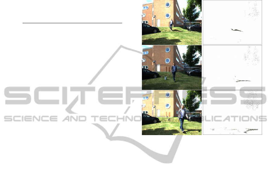
Figure 5: Dynamic shadow detection based on image dif-
ferencing (frames 180, 520, and 1741). These are the raw
detected shadow pixels. The spurious shadow pixels in the
top right of the images are removed with morphological op-
erations.
7 EXPERIMENTAL RESULTS
We have Matlab and C++ versions of the shadow de-
tection, and we have a Matlab implementation of the
illumination estimation.
In the C++ version shadow detection is running
at approx. 8 Hz on an Intel Core Duo 2 2.3 GHz
machine running Windows XP SP2, equipped with 2
GByte RAM. This framerate includes the stereo dis-
parity computations, and the construction of the ge-
ometry mesh from the depth data. Figure 5 illustrates
the shadow detection on some random frames from a
long image sequence with rapidly changing illumina-
tion conditions (partly overcast and very windy).
The expressions for estimating the illumination
conditions involve quantities relating to the geome-
try of the scene, namely the sky dome visibility frac-
tion V
a
and the surface normals. We construct trian-
gle meshes of the scene from the live disparity data
(an example mesh is shown in figure 2). The disparity
data is in 640 × 480 pixel resolution, which is mean
filtered with a kernel size of 5 × 5. A 160 × 120 reg-
ular vertex grid is imposed on the disparity map and
GRAPP 2011 - International Conference on Computer Graphics Theory and Applications
134
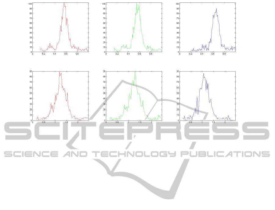
Figure 6: Top row: sky irradiance histograms for R, G, and B color channels. Bottom row: similar for sun irradiance. For
each histogram the horizontal axis shows the irradiance value with a scale factor k of 1, and the vertical axis is number of
pixels voting for that irradiance value. The histogram corresponds to the scene in figure 1.
the xyz position of each vertex is found by converting
the corresponding disparity value to depth and multi-
plying the pixel’s unit ray direction vector with that
depth. Two triangles are formed for every group of
4 vertices, resulting in 2 × 160 × 120 triangles, from
which triangles with normals almost perpendicular to
the viewing direction are discarded (typically trian-
gles that correspond to depth discontinuities). We get
per pixel normals by rendering the scene mesh using
a normal shader. For all renderings in this paper we
have used the RADIANCE rendering package, (Ward,
2009). Per pixel sky dome visibility is computed by
rendering irradiance values of the mesh (with mesh
albedo set to zero to avoid global illumination inter-
reflections) when illuminated with a sky dome of ra-
diance 1/π. Using this approach a normal pointing
straight into the sky and having un-occluded view of
the sky will receive an irradiance of 1, so the V
a
val-
ues will be in the range of 0 to 1 as desired. Figure 4
shows examples.
With per pixel geometry quantities, and with irra-
diance ratios C computed per detected shadow pixels
using eq. (10) we have a whole population of pixels
voting for the irradiances of the sky and the sun. Each
pixel, through eq. (13), contributes three channel val-
ues for the sky irradiance, and through eq. (11) for the
sun irradiance. This is computed for all shadow pixels
and histograms are formed of sky and sun irradiances
for each color channel, see figure 6.
From each of these histograms the most voted for
irradiance value is selected (histogram peak). Fu-
ture work includes either fitting a Gaussian distribu-
tion, employ a mean shift algorithm, or to use Ran-
dom Sample Consencus (RANSAC), to find the mean
more robustly than just taking peak value. In the ex-
ample in figure 6 the elected and finally scaled radi-
ance values are:
Sky radiance =
0.6548 0.6662 0.7446
Sun radiance =
60197 57295 51740
These numbers indicate primarily that the radi-
ance of the sun is 5 orders of magnitude higher than
that of the sky, which is consistent with the fact that
the sun’s subtended solid angle is 5 orders of magni-
tude smaller than a hemi-spherical sky dome, but as a
rule of thumb provides roughly the same irradiance as
the sky dome. Futhermore it can be noticed that the
sky’s color balance clearly is much more blue than
that of the sun. Figure 7 show more examples of ob-
jects rendered into scenes with illumination estimated
using the technique proposed in this paper.
Qualitatively, judging from figures 1 and 7 the
generated results are encouraging and the estimated
illumination conditions visually match the real scene
conditions sufficiently well to be convincing. Sub-
sequently we present some more controlled experi-
ments.
Synthetic Geometry, Synthetic Illumination
To test the technique’s performance on a scene for
which ground truth is available for the illumination
a synthetic scene has been rendered at two time in-
stances with a shadow casting pole moving from one
frame to another, see figure 8.
The ground truth sky radiance for the scene in fig-
ure 8 is [
0.0700 0.1230 0.1740
] and the sun ra-
OUTDOOR ILLUMINATION ESTIMATION IN IMAGE SEQUENCES FOR AUGMENTED REALITY
135
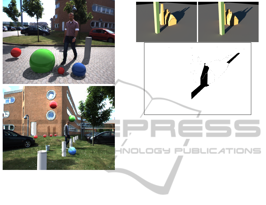
Figure 7: Two examples of scenes with augmentations us-
ing the proposed technique for estimating illumination from
automatically detected shadows.
diance is [
72693 57178 42247
]. The estimated
sky radiance is [
0.0740 0.1297 0.1804
] and the
sun radiance is [
71687 55488 40622
], i.e., esti-
mations are within 5% of ground truth. A large pro-
portion of the deviation between ground truth and es-
timation result is believed to be due to influence from
indirect illumination (light reflecting from one surface
on to others), a phenomenon which is not taken intro
account by the applied two part illumination model
(sun and sky are assumed to be the only illuminants
in the scene).
Real Geometry, Synthetic Illumination
To test the performance under more realistic con-
ditions a pair of images were produced where the
dynamic objects are synthetic, but they are casting
shadow on real mesh geometry obtained from the
stereo camera. Figure 10 illustrates how these images
were generated.
The two frame image sequence thus generated
shows synthetically generated dynamic shadows on
real stereo geometry, using real camera images as
scene albedo, and yet we still have perfect ground
truth for the illumination, since the shadows are ren-
dered into the image.
Figure 8: Top: Two frames of a synthetic scene. Bottom:
detected dynamic shadow pixel population to be used for
illumination estimation.
The ground truth sky radiance for the scene in fig-
ure 10 is [
1.0109 1.1644 1.2085
] and the sun ra-
diance is [
83082 81599 73854
]. The estimated
sky radiance is [
1.0658 1.2212 1.2614
] and the
sun radiance is [
88299 82764 79772
], i.e., esti-
mations are within roughly 5% of ground truth, except
for the red channel of the sun, which shows an error
of around 8%. Figure 11 shows an augmentation into
this semi-synthetic scene with the estimated illumina-
tion.
As in the previous all synthetic data example the
discrepancy is believed to be due to not explicitly
taking indirect illumination into account. For exam-
ple the sun’s red channel is somewhat over-estimated,
since in the shadow a lot of red-toned illumination
from the brick-walled building in the background of
figure 10 vanishes, and the assumed simplified illu-
mination model can only “explain” this by estimating
the sun’s red channel higher than it actually is.
Real Geometry, Real Illumination
As a final example of the performance of the pre-
sented technique we return to the scene from figure
1, this time to another frame in the same sequence,
approximately 6 seconds earlier, see figure 9.
In figure 1 the sky radiance is estimated to
[
0.6548 0.6662 0.7446
] and the sun ra-
diance to [
60197 57295 51740
]. From
the frame in figure 9 the same values are es-
timated at [
0.6106 0.5874 0.6746
] and
[
68927 69784 62741
], respectively.
A significant change in the estimated illumination
is noted on the quantitative level, although visually
the augmentation in the two cases is equally convinc-
GRAPP 2011 - International Conference on Computer Graphics Theory and Applications
136
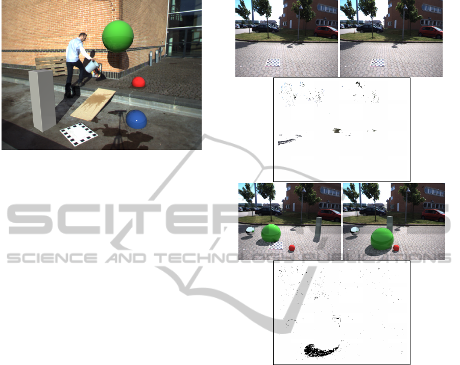
Figure 9: Even with the shadow falling on completely dif-
ferent materials and with completely different geometric
properties the estimation illumination is comparable to that
of figure 1.
ing. The relatively large quantitative differences are,
in addition to the fact that this scene in particular in-
volves substantial indirect illumination contributions,
due to a lot of the pixels for the sunlit brick wall
are saturated in the red channel, i.e., exceed 255 in
pixel value. Naturally, such imperfect image expo-
sure makes it difficult for the technique to estimate
proper results.
8 DISCUSSIONS AND FUTURE
WORK
The work described here is intended for sequences
of limited length (up to minutes). Futhermore it re-
quires the presence of dynamic objects to cast shad-
ows. We are developing additional techniques which
will be bootstrapped by the technique presented here,
but afterwards will be able to handle illumination es-
timation also in the absence of dynamic shadows, and
over very long image sequences.
The described technique is based on an assump-
tions that surfaces in the scene are predominantly
diffuse. While this is a fair assumption for much
outdoor material it is far from satisfactory to have
this constraint. We are presently pursuing analysis
of very long time sequences (full day, several days)
and are developing techniques to classify pixels that
do not agree with the majority on how the illumi-
nation in the scene changes. Those pixels are either
glossy/specular, a leaf has fallen on the surface, or
even snow. Our ambition is to develop techniques that
are robust enough to handle seasonal changes.
In the illumination estimation approach presented
in section 6 the illumination model does not take into
Figure 10: First row: frames 25 and 30 from real stereo im-
age sequence. Second row: detected shadow pixels from
trees moving in the wind. Third row: frame 30 augmented
with moving synthethic objects, using the illumination es-
timated from the shadow pixels in row two. Notice the re-
flection of the sky in the artificial chrome ball to the left.
account the indirect global illumination contribution
from other surfaces in the scene. We are presently
rephrasing this work into a framework that does take
this into account. Moreover, we are investigating how
to employ a more realistic sky model than the uniform
radiance sky dome used here. A more realistic, non-
uniform sky dome could be the Perez model, (Perez
et al., 1993), or the Preetham model, (Preetham et al.,
1999).
The shadow detection is presently running at 8 Hz
including the stereo disparity computation. The illu-
mination estimation process itself poses no real com-
putational load, but the required ambient occlusion
map is not straight forward to obtain as this requires
some form of ray casting. Real-time global illumina-
tion methods are beginning to appear in the litterature,
OUTDOOR ILLUMINATION ESTIMATION IN IMAGE SEQUENCES FOR AUGMENTED REALITY
137

Figure 11: Augmentation into the scene were the illumina-
tion was estimated from the shadows of moving augmenta-
tions, which in turn were rendered into the original scene
with illumination estimated from the shadows of trees mov-
ing in the wind.
and for the use in conjunction with the work in this
paper we only need ambient occlusion factors for the
detected shadow pixels, not for the entire image.
9 CONCLUSIONS
We have presented a technique for adaptively estimat-
ing outdoor daylight conditions directly from video
imagery, and the technique has a potential for real-
time operation. The main scientific contribution is a
theoretically well-founded technique for estimation of
the radiances of sky and sun for a full outdoor illumi-
nation model directly from Low Dynamic Range im-
age sequences. The main contribution from a systems
point of view is a demonstration that automatic detec-
tion of dynamic shadows can feed information to the
illumination estimation.
The presented work an be used for rendering vir-
tual objects in Augmented Reality, but we conjecture
that illumination estimation can also make many clas-
sical computer vision techniques more robust to illu-
mination changes.
ACKNOWLEDGEMENTS
This work is funded by CoSPE project (project num-
ber 26-04-0171) and the BigBrother project (project
number 274-07-0264) under the Danish Research
Agency. This funding is gratefully acknowledged.
REFERENCES
Barsi, L., Szimary-Kalos, L., and Szecsi, L. (2005). Image-
based illumination on the gpu. Machine Graphics and
Graphics, 14(2):159 – 169.
Blanco-Muriel, M., Alarc
´
on-Padilla, D. C., L
´
opez-
Moratalla, T., and Lara-Coira, M. (2001). Computing
the solar vector. Solar Energy, 70(5):431 – 441.
Boivin, S. and Gagalowicz, A. (2001). Image-based ren-
dering of diffuse, specular and glossy surfaces from
a single image. In Proceedings: ACM SIGGRAPH
2001, pages 107–116.
Boivin, S. and Gagalowicz, A. (2002). Inverse rendering
from a single image. In Proceedings: First European
Conference on Color in Graphics, Images and Vision,
Poitiers, France, pages 268–277.
Cao, X., Shen, Y., Shah, M., and Foroosh, H. (2005). Sin-
gle view compositing with shadows. The Visual Com-
puter, pages 639 – 648.
Chalidabhongse, T., Kim, K., Harwood, D., and Davis, L.
(2003). A Perturbation Method for Evaluating Back-
ground Subtraction Algorithms. In Joint IEEE Inter-
national Workshop on Visual Surveillance and Perfor-
mance Evaluation of Tracking and Surveillance, Nice,
France.
Debevec, P. (1998). Rendering synthetic objects into real
scenes: Bridging traditional and image-based graph-
ics with global illumination and high dynamic range
photography. In Proceedings: SIGGRAPH 1998, Or-
lando, Florida, USA.
Debevec, P. (2002). Tutorial: Image-based lighting. IEEE
Computer Graphics and Applications, pages 26 – 34.
Debevec, P. and Malik, J. (1997). Recovering high dynamic
range radiance maps from photographs. In Proceed-
ings: SIGGRAPH 1997, Los Angeles, CA, USA.
Dutr
´
e, P., Bekaert, P., and Bala, K. (2003). Advanced
Global Illumination. A. K. Peters.
Finlayson, G., Hordley, S., and Drew, M. (2002). Remov-
ing shadows from images. In Heyden, A., Sparr, G.,
Nielsen, M., and Johansen, P., editors, Proceedings:
European Conference on Computer Vision, pages 823
– 836.
Gibson, S., Cook, J., Howard, T., and Hubbold, R. (2003).
Rapic shadow generation in real-world lighting envi-
ronments. In Proceedings: EuroGraphics Symposium
on Rendering, Leuwen, Belgium.
Hara, K., Nishino, K., and Ikeuchi, K. (2005). Light source
position and reflectance estimation from a single view
without the distant illumination assumption. IEEE
Trans. Pattern Anal. Mach. Intell., 27(4):493–505.
Havran, V., Smyk, M., Krawczyk, G., Myszkowski, K.,
and Seidel, H.-P. (2005). Importance Sampling for
Video Environment Maps. In Eurographics Sympo-
sium on Rendering 2005, pages 31–42,311, Konstanz,
Germany.
Horprasert, T., Harwood, D., and Davis, L. S. (1999). A sta-
tistical approach for real-time robust background sub-
traction and shadow detection. In Proceedings: IEEE
ICCV’99 FRAME-RATE Workshop, Kerkyra, Greece.
GRAPP 2011 - International Conference on Computer Graphics Theory and Applications
138

Huerta, I., Holte, M., Moeslund, T., and Gonz
`
alez, J.
(2009). Detection and removal of chromatic moving
shadows in surveillance scenarios. In Proceedings:
IEEE ICCV’09, Kyoto, Japan.
Jacobs, K. and Loscos, C. (2004). State of the art report on
classification of illumination methods for mixed real-
ity. In EUROGRAPHICS, Grenoble, France.
Kanbara, M. and Yokoya, N. (2004). Real-time estimation
of light source environment for photorealistic aug-
mented reality. In Proceedings of the 17th ICPR,
Cambridge, United Kingdom, pages 911–914.
Kim, K., Chalidabhongse, T., Harwood, D., and Davis, L.
(2005). Real-time Foreground-Background Segmen-
tation using Codebook Model. Real-time Imaging,
11(3):167–256.
Loscos, C., Drettakis, G., and Robert, L. (2000). Interative
virtual relighting of real scenes. IEEE Transactions
on Visualization and Computer Graphics, 6(4):289 –
305.
Madsen, C. B. and Laursen, R. (2007). A scalable gpu-
based approach to shading and shadowing for photo-
realistic real-time augmented reality. In Proceedings:
International Conference on Graphics Theory and Ap-
plications, Barcelona, Spain, pages 252 – 261.
Madsen, C. B., Moeslund, T. B., Pal, A., and Balasubrama-
nian, S. (2009). Shadow detection in dynamic scenes
using dense stereo information and an outdoor illu-
mination model. In Koch, R. and Kolb, A., editors,
Proceedings: 3rd Workshop on Dynamic 3D Imaging,
in conjunction with Symposium of the German Associ-
ation for Pattern Recognition, Jena, Germany, pages
100 – 125.
Marchand, J. A. and Onyango, C. M. (2000). Shadow-
invariant classification for scenes illuminated by day-
light. Journal of the Optical Society of America,
17(11):1952 – 1961.
Nielsen, M. and Madsen, C. (2007). Graph cut based seg-
mentation of soft shadows for seemless removal and
augmentation. In Proceedings: Scandinavian Con-
ference on Image Analysis, Aalborg, Denmark, pages
918 – 927.
Perez, R., Seals, R., and Michalsky, J. (1993). All-weather
model for sky luminance distribution–preliminary
configuration and validation. Solar Energy, 50(3):235
– 245.
PointGrey (2009). Bumblebee XB3 stereo
camera, Point Grey Research, Inc.
www.ptgrey.com/products/bumblebee/index.html.
Prati, A., Mikic, I., Trivedi, M., and Cucchiara, R. (2003).
Detecting Moving Shadows: Algorithms and Evalua-
tion. IEEE Transactions on Pattern Analysis and Ma-
chine Intelligence, 25:918–923.
Preetham, A. J., Shirley, P., and Smits, B. (1999). A practi-
cal analytic model for daylight. In Proceedings of the
26th annual conference on Computer graphics and in-
teractive techniques, SIGGRAPH ’99, pages 91–100,
New York, NY, USA. ACM Press/Addison-Wesley
Publishing Co.
Salvador, E., Cavalarro, A., and Ebrahimi, T. (2004).
Shadow identification and classification using invari-
ant color models. Computer Vision and Image Under-
standing, 95:238 – 259.
Sato, I., Sato, Y., and Ikeuchi, K. (1999a). Acquiring a radi-
ance distribution to superimpose virtual objects onto
a real scene. IEEE Transactions on Visualization and
Computer Graphics, 5(1):1–12.
Sato, I., Sato, Y., and Ikeuchi, K. (1999b). Illumination dis-
tribution from brightness in shadows: adaptive esti-
mation of illumination distribution with unknown re-
flectance properties in shadow regions. In Proceed-
ings: International Conference on Computer Vision,
pages 875–882.
Wang, Y. and Samaras, D. (2008). Estimation of multiple
directional illuminants from a single image. Image
Vision Computing, 26(9):1179–1195.
Ward, G. (2009). Radiance - Synthetic Imaging System. rad-
site.lbl.gov/radiance/.
Yu, Y., Debevec, P., Malik, J., and Hawkins, T. (1999).
Inverse global illumination: Recovering reflectance
models of real scenes from photographs. In Pro-
ceedings: SIGGRAPH 1999, Los Angeles, California,
USA, pages 215 – 224.
OUTDOOR ILLUMINATION ESTIMATION IN IMAGE SEQUENCES FOR AUGMENTED REALITY
139
