
MULTI-RESOLUTION VIRTUAL PLANE BASED 3D
R
ECONSTRUCTION USING INERTIAL-VISUAL DATA FUSION
Hadi Aliakbarpour and Jorge Dias
Institute of Systems and Robotics, DEEC, University of Coimbra, Coimbra, Portugal
Keywords:
Computer vision, Sensor fusion, IMU, 3D Reconstruction, Homography, Sensor network, Virtual camera,
Virtual plane, Quadtree.
Abstract:
In this paper a novel 3D volumetric reconstruction method, based on the fusion of inertial and visual infor-
mation and applying a quadtree-based compression algorithm, has been proposed. A network of cameras is
used to observe the scene. Then beside of each camera, a fusion-based virtual camera is defined. The trans-
formations among the cameras have been estimated. Then a set of horizontal virtual planes have been passed
through the volumetric scenes. The intersections of these virtual planes and the object within the scene, or
in other words the virtual registration layers, have been obtained by using the concept of homography. Then
quadtree-based decomposition has been applied to the registration layers and consequently the obtained layers
(2D) are stacked to produce the 3D reconstruction of the object. The proposed method has the ability of ad-
justing the compactness or the resolution of the result which can be defined with respect to the application or
the storage resources, specially when the intention is to keep the sequence of 3D models in a dynamic scene.
1 INTRODUCTION
Building 3D volumetric models of the objects is one
of the major research topics in the computer vision
area. There have been many works in the area of
3D reconstruction. Khan in (Khan et al., 2007) pro-
posed a homographic framework for the fusion of
multi-view silhouettes. A marker-less 3D human mo-
tion capturing approach is introduced in (Michoud
et al., 2007) using multiple views. Zhang in (Zhang
et al., 2003) introduced an algorithm for 3D projec-
tive reconstruction based on infinite homography. Lai
and Yilmaz in (Lai and Yilmaz, 2008) used images
from uncalibrated cameras for performing projective
reconstruction of buildings based on Shape From Sil-
houette (SFS) approach where buildings structure is
used to compute vanishing points. Aliakbarpour and
Dias in (Aliakbarpour and Dias, 2010a) proposed a
method to SFS-based 3D reconstruction by fusion of
inertial and visual information. 3D reconstruction of
a dynamic scene is investigated in (Calbi et al., 2006)
by Calibi. Franco in (Franco and Boyer, 2005) used
a Bayesian occupancy grid to represent the silhouette
cues of objects.
The use of IMU sensors to accompany compute
vision applications is recently attracting attentions of
the researchers. Dias in (Dias et al., 2002) inves-
Figure 1: Fusion-based virtual camera.
t
igated the cooperation between visual and inertial
information. Lobo and Dias(Lobo and Dias, 2007)
proposed an efficient method to estimate the relative
pose of a camera and an IMU. Mirisola in (Mirisola
and Dias, 2007) used a rotation-compensated imagery
for the aim of trajectory by aiding inertial data. Fu-
sion of image and inertial data is also investigated
by Bleser (Bleser et al., 2006) for the sake of track-
ing in the mobile augmented reality. In our recent
work(Aliakbarpour and Dias, 2010b), the problem of
3D reconstruction using inertial and visual informa-
tion has been investigated. Tree-based data structures
are appropriate to store spatial data. Most often they
are used to partition a 2D space (quadtrees) or 3D
space (octrees). An octree-based method to construct
the 3D model of an object using SFS method is pre-
sented in (Kampel et al., 2002) by Kampel. An image
registration approach based on reconstructed 3D oc-
trees is proposed in (Ruwwe et al., 2008) by Ruwwe.
Liu and Cooper in (Liu and Cooper, 2010) an ap-
proach to multi-view image-based 3D reconstruction
112
Aliakbarpour H. and Dias J..
MULTI-RESOLUTION VIRTUAL PLANE BASED 3D RECONSTRUCTION USING INERTIAL-VISUAL DATA FUSION.
DOI: 10.5220/0003317901120118
In Proceedings of the International Conference on Computer Vision Theory and Applications (VISAPP-2011), pages 112-118
ISBN: 978-989-8425-47-8
Copyright
c
2011 SCITEPRESS (Science and Technology Publications, Lda.)
in which using octree to enhance the process speed
is proposed. Moon et. al. in (Moon and Pan, 2010)
proposed a human identification method for the intel-
ligent video surveillance system by applying octree-
based color quantization technique. A method to re-
duce 3D point clouds which are acquired by laser
range finder is proposed in (Song et al., 2009) where
octree is used to compress the data. Quadtree-based
decomposition of image data is used in (Colleu et al.,
2009) by Colleu et. al. for the sake of 3D video repre-
sentation. Semi-automatically objects labeling using
quadtree-based partitioning is proposed by Wu and
Yang in (Wu and Yang, 2009).
This paper presents an approach for volumetric 3D
reconstruction of an object within a scene. The scene
is observed by a network of cameras. The cameras
are coupled with an IMU. Fusion of inertial and vi-
sual information in each couple made it possible to
consider a network of downward-looking virtual cam-
eras whose images planes are horizontal. Moreover, a
set of horizontal virtual planes which pass through the
3D space of the scene is considered, by using the iner-
tial data. Then the intersection of each 3D world plane
with the object volume has been obtained by using the
concept of homography. In order to reduce the stor-
age resource’s usage and moreover enhance further
processing speed(Liu and Cooper, 2010), a quadtree-
based compression method has been applied. An al-
gorithm has been introduced in order to perform the
proposed compact 3D reconstruction method which
produces a set of quadtree data structure as the re-
sult. This paper is organized as following: camera
model is introduced in Sec. 2. An image registration
method by fusion of inertial and visual information is
proposed in Sec. 3. In Sec. 4 the compact 3D re-
construction algorithm by using quadtree method is
described. Experimental results are demonstrated and
discussed in Sec. 5 and eventually the conclusion is
provided in Sec. 6.
2 CAMERA MODEL
In a pinhole camera model, a 3D point X =
[
X Y Z 1
]
T
in the scene and its corresponding
projection x =[
x y 1
]
T
are related via the fol-
lowing equation (Hartley and Zisserman, 2003):
x = K [R|t] X (1)
where K is the camera calibration matrix, R and t are
rotation matrix and translation vector between world
and camera coordinate systems, respectively. The
camera matrix K, which is also called intrinsic pa-
rameter matrix, is defined by (Hartley and Zisserman,
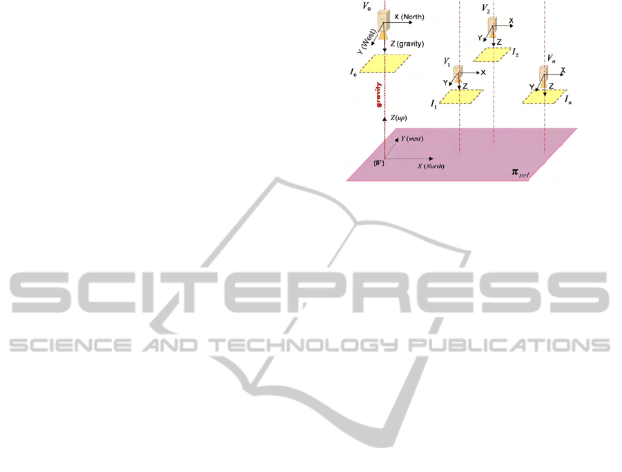
Figure 2: A network of virtual cameras: The coordinate
frames of all virtual cameras are aligned to the world refer-
ence frame.
2003):
K =
f
x
0 u
0
0 f
y
v
0
0 0 1
(2)
in which f
x
and f
y
represent the focal length of the
camera in the directions of x and y. The u
0
and v
0
are
the elements of the principal point vector, p .
3 FUSION-BASED IMAGE
REGISTRATION
The idea is to use a network of cameras to observe the
scene. Each camera within the network is rigidly cou-
pled with an IMU. Using fusion of inertial and visual
information it becomes possible to consider a virtual
camera instead of each couple. Such a virtual cam-
era has a horizontal image plane and its optical axis is
parallel to the gravity and is downward-looking. As
a result, the image plane is aligned to the earth fixed
reference frame. Fig. 2 shows a network of such vir-
tual cameras. In order to obtain image plane of virtual
camera, a homography-based approach described in
(Aliakbarpour and Dias, 2010a) has been used which
fuses inertial data from IMU and image plane of real
camera to produce the corresponding virtual camera’s
image plane. As described in (Aliakbarpour and Dias,
2010a), the homography matrix which transforms the
real camera image plane to its corresponding virtual
camera image plane can be expressed as following:
V
H
C
= K
V
R
C
K
−1
(3)
where
V
R
C
is the rotation matrix among the real and
virtual cameras(Aliakbarpour and Dias, 2010a). The
way of obtaining
V
R
C
is explained in (Aliakbarpour
and Dias, 2010a).
By taking the advantage of inertial data, a hori-
zontal word plane π
ref
, which is supposed to be com-
MULTI-RESOLUTION VIRTUAL PLANE BASED 3D RECONSTRUCTION USING INERTIAL-VISUAL DATA
FUSION
113
mon between all virtual cameras, has been defined in
the world reference frame{W} (see Fig. 2). As men-
tioned, the idea is to register virtual image data on
the reference plane π
ref
. The reference 3D plane
π
ref
is defined such a way that it spans the X and
Y axis of {W} and it has a normal parallel to the Z.
In this proposed method the idea is to not using any
real 3D plane inside the scene for estimating homog-
raphy. Hence we assume there is no a real 3D plane
available in the scene so our {W} becomes a virtual
reference frame and consequently π
ref
is a horizon-
tal virtual plane on the fly. Although {W} is a virtual
reference frame however it needs to be somehow de-
fined and fixed in the 3D space. Therefore here we
start to define {W} and as a result π
ref
. With no loss
of generality we place O
W
, the center of {W}, in the
3D space such a way that O
W
has a height d w.r.t the
first virtual camera, V
0
. Again with no loss of gen-
erality we specify its orientation as same as the earth
fixed reference. Then as a result we can describe the
reference frame of a virtual camera {V} w.r.t {W} via
the following homogeneous transformation matrix
W
T
V
=
W
R
V
t
0
1×3
1
(4)
where
W
R
V
is a rotation matrix defined as (see Fig.
2):
W
R
V
=
1 0 0
0 −1 0
0 0 −1
(5)
and t is a translation vector of the V ’s center w.r.t
{W}. Obviously using the preceding definitions and
conventions, for the first virtual camera we have t =
[
0 0 d
]
T
.
After obtaining the virtual camera’s image plane
(from now on we call it virtual image plane) it is
desired to find a homography matrix
π
H
V
that trans-
forms points from the virtual image plane I
′
to the
common world 3D plane π
ref
(recalling that these two
planes are defined to be parallel). Here we continue to
formally define such a homography matrix using the
rotation and translation between these two planes (I
′
and π
ref
). A 3D point X = [
X Y Z 1
]
T
lying on
π
ref
can be projected onto virtual image plane as
x =
π
ref
H
v
X (6)
where
π
ref
H
v
is a homography matrix which maps the
π
ref
to the virtual image plane and is defined by
π
ref
H
v
= K[
r1 r2 t
] (7)
in which r1, r2 and r3 are the columns of the 3× 3
rotation matrix and t is the translation vector between
the π
ref
and camera center (Hartley and Zisserman,
2003). We recall that all virtual cameras have the
same rotation w.r.t world reference frame {W}. In
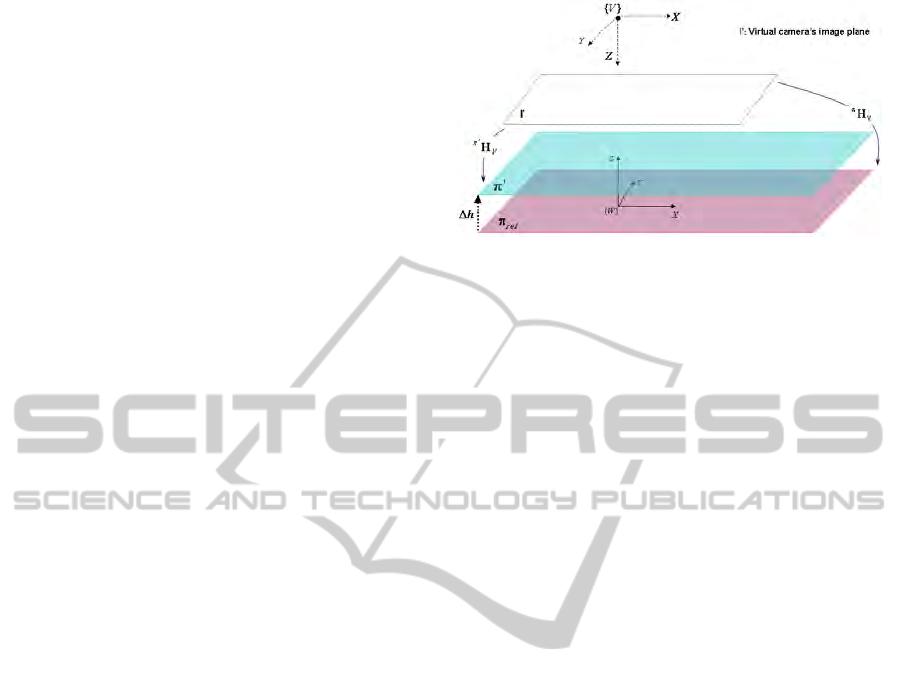
Figure 3: Extending homography for planes parallel to π
ref
.
other words it can be thought there is no rotation
among the virtual cameras.
W
R
V
or the rotation ma-
trix between a virtual camera and {W} was described
through Eq. (5). Considering
W
R
V
from Eq. (5), π
ref
as the interesting world plane and t = [
t
1
t
2
t
3
]
T
as the translation vector (among I
′
and π
ref
) and even-
tually K as camera calibration matrix (K is defined in
Eq. 2), the Eq. (7) can be rewritten as :
π
H
−1
V
=
f
x
0 f
x
t
1
+ u
0
t
3
0 − f
y
f
y
t
2
+ v
0
t
3
0 0 t
3
(8)
In order to estimate t an approach described in (Ali-
akbarpour and Dias, 2010a) will be used.
The homography matrix from virtual image plane
to the world 3D plane π
ref
has been already obtained
as
π
H
V
( Eq. (8)). For the sake of multi-layer recon-
struction, it is desired to also obtain the homography
matrix from a virtual image to another world 3D plane
parallel to π
ref
once we already have
π
H
V
(see Fig.
3). Lets consider π
′
as a 3D plane which is parallel to
π
ref
and has a height ∆h w.r.t it. Then by substituting
t
3
in the equation (8) with t
3
+ ∆h and expressing it
via
π
H
V
(the available homography between the vir-
tual camera image plane and π
ref
) we have:
π
′
H
−1
V
=
π
H
V
+ ∆h
0
2×2
P
0 1
(9)
where P = [
u
0
v
0
]
T
is the principal point of the
virtual camera V.
4 COMPACT 3D
RECONSTRUCTION
The method for registering image data onto a set of
virtual horizontal planes based on the concept of ho-
mography was introduced in Sec. 3. Indeed in our
case the homography transformation can be basically
interpreted as shadow on each virtual horizontal 3D
VISAPP 2011 - International Conference on Computer Vision Theory and Applications
114

Figure 4: Quadtree decomposition: left) A binary image.
right) The binary array corresponding to the (a).
Figure 5: Quadtree decomposition: left) Quadtree-based
block decomposition of the region. right) Quadtree repre-
sentation of the decomposed blocks in (a).
plane created by a light source located at the cam-
era position. Considering several cameras (remem-
bering light sources) which are observing the object
then different shadows will be created on the virtual
horizontal 3D planes. Then the intersection between
each of these planes and the observed object can be
computed by using the intersections of all shadows.
The result of the intersection is a plane and from now
will be referred as the registration plane. Here, the
idea is to use the concept of quadtree in order to keep
or store the registration planes. The main advantage
of using quadtree is to use less memory. Moreover
it will increase the speed of further processing. We
continue to briefly introduce the concept of quadtree-
based image representation. Beforehand we assume
to have a 2
n
× 2
n
binary image. The quadtree-based
image representation is based on the successive sub-
division of the image into four equal-size quadrants
(Samet, 1981). If the image does not consist entirely
of 1’s or entirely 0’s, then it will be subdivided into
four quadrants. Then for each quadrant we repeat the
checking of the mentioned consistency until we get
square blocks (might be even a single pixel) that con-
tain homogeneous values (entirely 1’s or entirely 0.s).
Fig. 4-left shows a binary image as a sample. Its cor-
responding binary array can be seen in Fig. 4-right.
Based on the described algorithm, the binary array is
decomposed in blocks which is represented in Fig. 5-
left. The quadtree form of the decomposition block is
demonstrated in Fig. 5-right.
In order to perform the proposed 3D reconstruc-
tion method, an algorithm (Alg. 1) is provided which
expresses the steps to do it. Here {camera} and
{virtual camera} are respectively the sets of all cam-
eras and virtual cameras , I indicates the image plane
Figure 6: Left: Cat statue, Middle: Couple of camera-IMU
sensor, Right: A snapshot of the scene.
of a real camera, I
′
indicates the image plane of a vir-
tual camera and I
”
indicates a virtual 3D plane. The
functions height() and width() get an image and re-
turn its height and width, respectively. The function
card() is used to return the cardinality of the given
set. The function Quadtree(R,blocks
size
) receives the
R, as a registration plane and blocks
size
as the size of
the blocks to be used for the decomposition (it can be
thought as the compactness resolution). Eventually,
the algorithm returns Q as a collection of compact 2D
registration planes. The number of elements in this
collection is h
max
+ 1 and the the distance among the
planes is ∆h . Indeed ∆h can be though as the hori-
zontal resolution in the 3D reconstruction.
Algorithm 1: Multi-resolution virtual Plane based 3D re-
construction using inertial-visual data fusion. The resolu-
tion of the result depends to the △h and blocks
size
param-
eters. △h indicates the vertical distance (intervals) among
the world virtual planes (see Fig. 3) and blocks
size
stands
for the size of blocks to be used for quadtree-based decom-
position.
for each v involved in {virtual camera} begin
obtain I
′
v
as the corresponding virtual image plane
end
Initialize Q as a collection of quadtrees
for h = 0 to h
max
step ∆h begin
for each v involved in {virtual camera} begin
obtain projection I
”v
from v to π
h
end
for each i ∈ {1..height(I
”v
)} begin
for each j ∈ {1..width(I
”v
)} begin
n
c
= card({virtualcamera}) //cardinality
R(i, j) =
∏
n
c
v=1
I
”v
(i, j)
end
end
Q(h)=Quadtree(R,blocks
size
)
end
return Q // as volumetric 3D reconstruction of the object
5 EXPERIMENTS
Experimental results of the proposed method are de-
scribed here. The idea is to perform the 3D re-
construction of a cat statue. Fig. 6 shows a cat
statue, a couple of Camera-IMU and a snapshot of
MULTI-RESOLUTION VIRTUAL PLANE BASED 3D RECONSTRUCTION USING INERTIAL-VISUAL DATA
FUSION
115
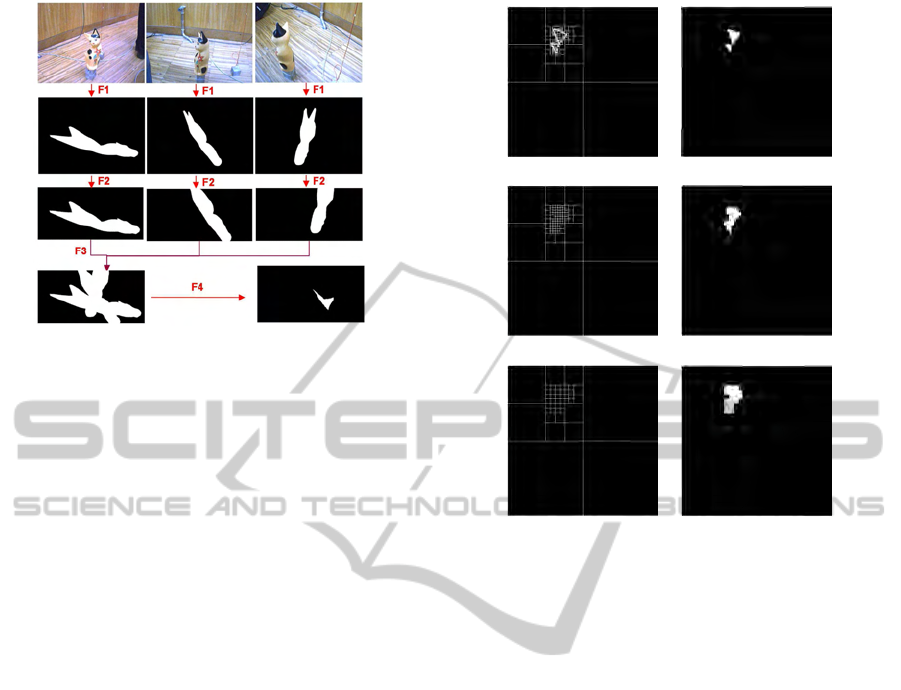
Figure 7: Steps to reach one 2D layer among 47 used lay-
ers for 3D reconstruction (in this example the layer height
is 380mm). F1: Reproject black and white images to
virtual camera image plane. ( after background subtrac-
tion and binarization) F2: Reprojection of virtual image
plane onto a 2D world virtual plane (registration plane) at a
height=380mm. F3: Putting the three world virtual planes
(merging). F4: Keeping just the intersected points.
the setup, from left to right respectively. The used
camera is a simple FireWire Unibrain camera and
a MTi-Xsens containing gyroscopes, accelerometers
and magnetometers is used as the IMU. Firstly the
intrinsic parameters of the camera camera is esti-
mated using Bouguet Camera Calibration Toolbox
(Bouguet, ) and then Camera Inertial Calibration
Toolbox (Lobo and Dias, 2007) is used for the sake of
extrinsic calibration between the camera and IMU (to
estimate
C
R
IMU
). The IMU-Camera couple is placed
in some different positions. A simple and thin string
is hanged near to the object. Two points of the string
are marked. Then the relative heights between these
two marked points and the first camera (indeed here
the IMU-camera couple in the first position) are mea-
sured manually. The relative heights can also be mea-
sured using some appropriate devices such as altime-
ters. Note that these two points are not needed to
necessarily be on a vertical line, but since we did
not have altimeter available, then we used two points
from a vertically hanged string in order to minimize
the measuring error. Afterwards, in each position a
pair of imagery-inertial data is grabbed. Fig. 7-top
row shows three exemplary images taken from three
different views. Then corresponding virtual images
are obtained. Fig. 7, 2
th
row shows the mentioned
virtual image planes. Using the mentioned 2-points-
heights method, which is described in (Aliakbarpour
and Dias, 2010a), the translations between cameras
in three position are estimated. By now we have
the images from views of virtual cameras. The next
step is to consider a set of registration planes (world
(a) (b)
(c) (d)
(e) (f)
Figure 8: Lefts: quadtree-based decomposition blocks, cor-
responding to an exemplary results. Right: result images
after applying the quadtree-based decomposition blocks.
Block sizes (resolutions): 1, 8 and 16 pixels corresponding
to the first, second and last raws, respectively.
virtual planes) and then reproject the three virtual
camera images onto these registration planes. Here
47 registration planes are used. The height of low-
est one is 480mm w.r.t first camera and the highest
one is 250mm. The distance between the virtual 3D
planes is considered as 5mm. As an example, the
3
th
row of Fig. 7 indicates the reprojection of the
three virtual camera images onto a registration plane
with height=380mm. The merging of these views are
shown in Fig. 7-bottom-left. Then the intersection
of them is presented in Fig. 7-bottom-right (as the
final registration plane, of course before compress-
ing). After having such a registration virtual plane,
the described quadtree algorithm has been applied on
them. Fig. 8 demonstrate different levels (resolution)
of quadtree-based decompositions applied on an ex-
emplary registration plane. Its left column indicates
some proposed decomposition blocks and the right
column shows the related image after using such de-
composition blocks (each row correspondsto a partic-
ular resolution). As can be seen in these images, for
such a registration plane in which just a small part is
occupied, it would be adequate to apply the quadtree
compression method in order to store as less as pos-
sible memory for keeping the registration layer. It is
VISAPP 2011 - International Conference on Computer Vision Theory and Applications
116
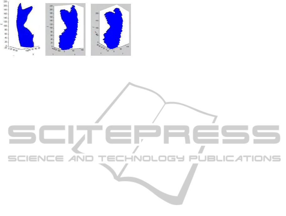
(a) (b) (c)
Figure 9: Results of quadtree virtual planes-based recon-
struction. They are after assembling the quadtree-based de-
composed registration layers (here, 47 layers). (a) maxi-
mum resolution (the decomposition block’s size is 1). For
(b) and (c) the size of the decomposition blocks are 8 and
16, respectively.
seen in this example, three quarters and two octants
are completely empty and just two octants are par-
tially occupied.
After repeating the operations for all 47 virtual
registration planes and assembling them together, the
result become the 3D reconstruction of the object.
Fig. 9 demonstrates the result of the 3D reconstruc-
tion. Fig. 9-a is the result when the maximum reso-
lution, or in other words blocks with the size equal to
one, has been used for each registration layer. Fig. 9-
b and Fig. 9-c are the results when the decomposition
blocks with the size of 8 and 16 have been used, re-
spectively. Depend to the application and the volume-
size of the scene, the resolution for the decomposi-
tion blocks and moreover, the horizontal resolution
(the distance between registration planes which is in-
dicated as △ h in the Algorithm 1), can be adjusted.
6 CONCLUSIONS
A multi-resolution 3D reconstruction using inertial-
visual data fusion has been proposed in this paper.
The proposed approach is based on obtaining the ho-
mography matrices among a set of virtual planes and
the image plane. An algorithm has been introduced
in order to perform the proposed 3D reconstruction
method and produces a set of quadtree data structure.
Depend to the application and the volume-size of the
scene, the resolution for the decomposition blocks can
be adjusted. Moreoverfor the same reason the vertical
distance among the virtual registration layers can be
increased or decreased in order to adjust the interest-
ing resolution. Finally, experimental results demon-
strate the efficacy of using the proposed method for
the sake of 3D volumetric reconstruction.
REFERENCES
Aliakbarpour, H. and Dias, J. (2010a). Human silhouette
volume reconstruction using a gravity-based virtual
camera network. In Proceedings of the 13th Interna-
tional Conference on Information Fusion, 26-29 July
2010 EICC Edinburgh, UK.
Aliakbarpour, H. and Dias, J. (2010b). Imu-aided 3d re-
construction based on multiple virtual planes. In
DICTA’10 (the Australian Pattern Recognition and
Computer Vision Society Conference), IEEE Com-
puter Society Press, 1-3 December 2010, Sydney, Aus-
tralia.
Bleser, Wohlleber, Becker, and Stricker. (2006). Fast and
stable tracking for ar fusing video and inertial sen-
sor data. pages 109–115. Short Papers Proceedings.
Plzen: University of West Bohemia.
Bouguet, J.-Y. Camera calibration toolbox for matlab. In
www.vision.caltech.edu/bouguetj.
Calbi, A., Regazzoni, C. S., and Marcenaro, L. (2006).
Dynamic scene reconstruction for efficient remote
surveillance. In IEEE International Conference
on Advanced Video and Signal Based Surveillance
(AVSS’06).
Colleu, T., Morin, L., Labit, C., Pateux, S., and Balter, R.
(2009). Compact quad-based representation for 3d
video. In 3DTV Conference: The True Vision - Cap-
ture, Transmission and Display of 3D Video, 2009,
pages 1 –4.
Dias, J., Lobo, J., and Almeida, L. A. (2002). Cooperation
between visual and inertial information for 3d vision.
In Proceedings of the 10th Mediterranean Conference
on Control and Automation - MED2002 Lisbon, Por-
tugal, July 9-12, 2002.
Franco, J.-S. and Boyer, E. (2005). Fusion of multi-view
silhouette cues using a space occupancy grid. In Pro-
ceedings of the Tenth IEEE International Conference
on Computer Vision (ICCV05).
Hartley, R. and Zisserman, A. (2003). Multiple View Geom-
etry in Computer Vision. CAMBRIDGE UNIVER-
SITY PRESS.
Kampel, M., Tosovic, S., and Sablatnig, R. (2002). Octree-
based fusion of shape from silhouette and shape from
structured light. In 3D Data Processing Visualization
and Transmission, 2002. Proceedings. First Interna-
tional Symposium on, IEEE.
Khan, S. M., Yan, P., and Shah, M. (2007). A homographic
framework for the fusion of multi-view silhouettes. In
Computer Vision, 2007. ICCV 2007. IEEE 11th Inter-
national Conference on.
Lai, P.-L. and Yilmaz, A. (2008). Projective reconstruc-
tion of building shape from silhouette images acquired
from uncalibrated cameras. In ISPRS Congress Bei-
jing 2008, Proceedings of Commission III.
Liu, S. and Cooper, D. (2010). Ray markov random fields
for image-based 3d modeling: Model and efficient in-
ference. In Computer Vision and Pattern Recogni-
tion (CVPR), 2010 IEEE Conference on, pages 1530
–1537.
MULTI-RESOLUTION VIRTUAL PLANE BASED 3D RECONSTRUCTION USING INERTIAL-VISUAL DATA
FUSION
117

Lobo, J. and Dias, J. (2007). Relative pose calibration be-
tween visual and inertial sensors. International Jour-
nal of Robotics Research, Special Issue 2nd Workshop
on Integration of Vision and Inertial Sensors, 26:561–
575.
Michoud, B., Guillou, E., and Bouakaz, S. (2007).
Real-time and markerless 3d human motion cap-
ture using multiple views. Human Motion-
Understanding, Modeling, Capture and Animation,
Springer Berlin/Heidelberg., 4814/2007:88–103.
Mirisola, L. G. B. and Dias, J. M. M. (2007). Exploiting
inertial sensing in mosaicing and visual navigation. In
In 6th IFAC Symposium on Inteligent Autonomous Ve-
hicles (IAV07), Toulouse, France, Sep. 2007.
Moon, H.-M. and Pan, S. B. (2010). A new human identi-
fication method for intelligent video surveillance sys-
tem. In Computer Communications and Networks (IC-
CCN), 2010 Proceedings of 19th International Con-
ference on., pages 1 –6.
Ruwwe, C., Keck, B., Rusch, O., Zolzer, U., and Loison,
X. (2008). Image registration by means of 3d octree
correlation. In Multimedia Signal Processing, 2008
IEEE 10th Workshop on, pages 515 –519.
Samet, H. (1981). Connected component labeling using
quadtrees. J. ACM, 28(3):487–501.
Song, W., Cai, S., Yang, B., Cui, W., and Wang, Y. (2009).
A reduction method of three-dimensional point cloud.
In Biomedical Engineering and Informatics, 2009.
BMEI ’09. 2nd International Conference on, pages 1
–4.
Wu, W. and Yang, J. (2009). Semi-automatically labeling
objects in images. Image Processing, IEEE Transac-
tions on, 18(6):1340 –1349.
Zhang, Q.-B., Wang, H.-X., and Wei, S. (2003). A new al-
gorithm for 3d projective reconstruction based on in-
finite homography. In Machine Learning and Cyber-
netics, 2003 International Conference on, IEEE.
VISAPP 2011 - International Conference on Computer Vision Theory and Applications
118
