
MODULATION-MODE ASSIGNMENT FOR SVD-ASSISTED
M
ULTIUSER MIMO SYSTEMS WITH CORRELATION
C´esar Benavente-Peces, Francisco Cano-Broncano
Universidad Polit´ecnica de Madrid, Ctra. Valencia. km. 7, 28031 Madrid, Spain
Sebastian Aust, Andreas Ahrens
Hochschule Wismar, University of Technology, Business and Design
Philipp-M¨uller-Straße 14, 23966 Wismar, Germany
Keywords:
Multiple-Input Multiple-Output System, Singular-Value Decomposition, Bit Allocation, Power Allocation,
Wireless Transmission, Multiuser Transmission.
Abstract:
Multiuser multiple-input multiple-output (MIMO) downlink (DL) transmission schemes experience both mul-
tiuser interference as well as inter-antenna interference. The singular value decomposition provides an appro-
priate mean to process channel information and allows us to take the individual user’s channel characteristics
into account rather than treating all users channels jointly as in zero-forcing (ZF) multiuser transmission tech-
niques. However, uncorrelated MIMO channels has attracted a lot of attention and reached a state of maturity.
By contrast, the performance analysis in the presence of antenna fading correlation, which decreases the chan-
nel capacity, requires substantial further research. The joint optimization of the number of activated MIMO
layers and the number of bits per symbol along with the appropriate allocation of the transmit power shows
that not necessarily all user-specific MIMO layers has to be activated in order to minimize the overall BER
under the constraint of a given fixed data throughput.
1 INTRODUCTION
Adaptive modulation is a promising technique to in-
crease the spectral efficiency of wireless communica-
tion systems by adapting the signal parameters, such
as modulation constellation or transmit power, dy-
namically to changing channel conditions. However,
in order to comply with the demand on increasing
available data rates in particular in wireless technolo-
gies, systems with multiple transmit and receive an-
tennas, also called MIMO systems, have become in-
dispensable and can be considered as an essential
part of increasing both the achievable capacity and
integrity of future generations of wireless systems
(K¨uhn, 2006). Besides, single-user MIMO transmis-
sion schemes for both non-frequency and frequency
selective MIMO channels have attracted a lot of at-
tention and reached a state of maturity (K¨uhn, 2006;
Ahrens and Lange, 2008). By contrast, MIMO-aided
multiple-user systems require substantial further re-
search where both multiuser as well as multi-antenna
interferences have to be taken into account.
Considering the entirety of the antennas of all mo-
bile terminals at one end and the antennas of the base
station at the other end of the communication link,
state of the art interference cancellation is based on
a central signal processing unit, e.g. a central unit
at the base station, where joint detection can be ap-
plied in the uplink (UL) and joint transmission in
the downlink (DL), respectively (Meurer et al., 2000;
Choi and Murch, 2004; Joham et al., 2005). Widely
used linear preprocessing techniques such as Mini-
mum Mean Square Error or Zero Forcing (ZF) have
attracted a lot of research and have reached a state
of maturity too (Choi and Murch, 2003). Therefore,
in this work SVD-assisted downlink (DL) multiuser
multiple-input multiple-output (MIMO) systems are
considered, which take the individual user’s channel
characteristics into account (Ahrens and Benavente-
Peces, 2010; Liu et al., 2008) rather than treating all
users channels jointly as in ZF multiuser transmission
techniques. Treating all user independently, adap-
tive modulation is a promising technique to increase
the spectral efficiency of wireless transmission sys-
tems by adapting the signal parameters, such as mod-
ulation constellation or transmit power, dynamically
333
Benavente-Peces C., Cano-Broncano F., Aust S. and Ahrens A..
MODULATION-MODE ASSIGNMENT FOR SVD-ASSISTED MULTIUSER MIMO SYSTEMS WITH CORRELATION.
DOI: 10.5220/0003314503330338
In Proceedings of the 1st International Conference on Pervasive and Embedded Computing and Communication Systems (PECCS-2011), pages
333-338
ISBN: 978-989-8425-48-5
Copyright
c
2011 SCITEPRESS (Science and Technology Publications, Lda.)

to individually changing channel conditions, where
the most beneficial choice of the number of activated
user-specific MIMO layers together with the number
of bits per symbol and the appropriate allocation of
the available transmit power offer a certain degree of
design freedom, which substantially affects the per-
formance of MIMO systems.
Against this background, in this paper a SVD-
assisted multiuser MIMO scheme is investigated,
where both multiuser interferences as well as multi-
antenna interferences are perfectly eliminated. The
novelcontributionof this paper is that we demonstrate
the benefits of amalgamating a suitable choice of ac-
tivated MIMO layers and number of bits per sym-
bol along with the appropriate allocation of the trans-
mit power under the constraint of a given fixed data
throughput. Besides the signal processing needed to
perfectly separate the users within a multiuser system,
multiple antenna systems are affected by signal corre-
lation among antennas, which produces a degradation
of the link performance, depending on the physical
relative position of the antennas and the mobility of
the front-ends and has to be taken into consideration.
The remaining part of this paper is organized as
follows: Section 2 introduces the multiuser system
model, whilethe considered quality criteria are briefly
reviewed in section 3. The associated performance
results are presented and interpreted in section 4. Fi-
nally, section 5 provides some concluding remarks.
2 MULTIUSER SYSTEM MODEL
The system model considered in this work consists of
a single base station (BS) supporting K mobile sta-
tions (MSs). The BS is equipped with n
T
transmit an-
tennas, while the kth (with k = 1,. .. ,K) MS has n
Rk
receive antennas, i. e. the total number of receive an-
tennas including all K MSs is given by n
R
=
∑
K
k=1
n
Rk
.
The (n
Rk
×1) user specific symbol vector c
k
to be
transmitted by the BS is given by
c
k
=
c
k,1
,c
k,2
,. .. ,c
k,n
Rk
T
. (1)
The vector c
k
is preprocessed before its transmission
by multiplying it with the (n
T
×n
Rk
) DL preprocess-
ing matrix R
k
and results in the (n
T
×1) user-specific
transmit vector
s
k
= R
k
c
k
. (2)
After DL transmitter preprocessing, the n
T
-
component signal s transmitted by the BS to the
K MSs results in
s =
K
∑
k=1
s
k
= Rc , (3)
with the (n
T
×n
R
) preprocessing matrix
R = (R
1
,R
2
,. .. ,R
K
) . (4)
In (3), the overall (n
R
×1) transmitted DL data vector
c combines all K DL transmit vectors c
k
(with k =
1,2,. .. ,K) and is given by
c =
c
T
1
,c
T
2
.. .,c
T
K
T
. (5)
At the receiver side, the (n
Rk
×1) vector u
k
of the kth
MS is given by
u
k
= H
k
s+ n
k
= H
k
Rc+ n
k
. (6)
and can be expressed by
u
k
= H
k
R
k
c
k
+
K
∑
i=1,i6=k
H
k
R
i
c
i
+ n
k
, (7)
where the MSs received signals experience both
multi-user and multi-antenna interferences. In (6), the
(n
Rk
×n
T
) channel matrix H
k
connects the n
T
BS spe-
cific transmit antennas with the n
Rk
receive antennas
of the kth MS.
It is quite common to assume that the coefficients
of the (n
Rk
×n
T
) channel matrix H
k
are independent
and Rayleigh distributed with equal variance. How-
ever, in many cases correlations between the trans-
mit antennas as well as between the receive anten-
nas can’t be neglected. There are several methods
to model and characterize antenna signal correlation
into a MIMO channel model for Rayleigh flat-fading
channels. In this work it is assumed that the corre-
lation among receive antennas is independent of the
correlation between transmit antennas. The way to
include the antenna signal correlation into the MIMO
channel model for Rayleigh flat-fading like channels
is given by (Durgin and Rappaport, 1999; Zelst and
Hammerschmidt, 2002) and results in
H
k
= H
1/2
Rx
·G·H
1/2
Tx
, (8)
where G is a (n
Rk
×n
T
) uncorrelated channel ma-
trix with independent, identically distributed com-
plex Gaussian zero-mean unit variance elements and
where (·)
1/2
stands for the square root of a matrix.
The (n
Rk
×n
Rk
) matrix H
Rx
is used to model the cor-
relation between the kth MS receive antennas. More-
over, the (n
T
×n
T
) transmit correlation matrix H
Tx
models the correlation between the transmit antennas.
The interference, which is introduced by the chan-
nel matrix H
k
, requires appropriate signal processing
strategies. A popular technique is based on the SVD
of the system matrix H
k
as described in (Ahrens and
Benavente-Peces, 2010). Therein, after pre- and post-
processing of the transmitted and received signal vec-
tors, the user-specific decision variables result in
y
k
= V
ku
P
k
c
k
+ w
k
, (9)
PECCS 2011 - International Conference on Pervasive and Embedded Computing and Communication Systems
334

c
(m)
k,ℓ
y
(m)
k,ℓ
w
(m)
k,ℓ
q
ξ
(m)
k,ℓ
q
p
(m)
k,ℓ
Figure 1: Resulting kth user-specific system model per
MIMO layer ℓ (with ℓ = 1,2, . .., n
Rk
) and per transmitted
symbol block m.
where interferences between the different antenna
data streams as well as MUI (multi-user interference)
imposed by the other users are avoided as shown
in (Ahrens and Benavente-Peces, 2010). In (9), the
(n
Rk
×n
Rk
) diagonal matrix V
ku
contains the non-
zero square roots of the eigenvalues of H
H
k
H
k
, e.g.,
V
ku
=
p
ξ
k,1
0 ··· 0
0
p
ξ
k,2
.
.
.
.
.
.
.
.
.
.
.
.
.
.
.
.
.
.
0 0 ···
p
ξ
k,n
Rk
, (10)
and the user-specific (n
Rk
×n
Rk
) diagonal power al-
location matrix is given by
P
k
=
√
p
k,1
0 ··· 0
0
√
p
k,2
.
.
.
.
.
.
.
.
.
.
.
.
.
.
.
.
.
.
0 0 ···
√
p
k,n
Rk
(11)
and simplifies to P
k
=
p
βI
n
Rk
×n
Rk
with the parame-
ter
p
β taking the transmit-power constraint into ac-
count as highlighted in (Ahrens and Benavente-Peces,
2010). Finally the additive, white Gaussian noise
(AWGN) vector is given by w
k
. The resulting system
model is depicted in Fig. 1
3 PERFORMANCE ANALYSIS
In general, the user-specific quality of data transmis-
sion can be informally assessed by using the signal-
to-noise ratio (SNR) at the detector’s input defined by
the half vertical eye opening and the noise power per
quadrature component according to
ρ =
(Half vertical eye opening)
2
Noise Power
=
(U
A
)
2
(U
R
)
2
, (12)
which is often used as a quality parameter (Ahrens
and Lange, 2008). The relationship between the
signal-to-noise ratio ρ = U
2
A
/U
2
R
and the bit-error
probability evaluated for AWGN channels and M-ary
Quadrature Amplitude Modulation (QAM) is given
by (Proakis, 2000)
P
BER
=
2
log
2
(M)
1−
1
√
M
erfc
r
ρ
2
. (13)
When applying the proposed system structure for
the kth user, the applied signal processing leads to dif-
ferent eye openings per activated MIMO layer ℓ (with
ℓ = 1,2, .. ., L and L ≤ n
Rk
describing the number of
activated user-specific MIMO layers) and per trans-
mitted symbol block m according to
U
(ℓ,m)
Ak
=
q
p
(m)
k,ℓ
·
q
ξ
(m)
k,ℓ
·U
(ℓ)
sk
, (14)
where U
(ℓ)
sk
denotes the half-level transmit amplitude
assuming M
ℓ
-ary QAM,
q
ξ
(m)
k,ℓ
represents the corre-
sponding positive square roots of the eigenvalues of
the matrix H
H
k
H
k
and
q
p
(m)
k,ℓ
represents the corre-
sponding power allocation weighting parameters. To-
gether with the noise power per quadrature compo-
nent, introduced by the additive, white Gaussian noise
(AWGN) vector w
k
in (9), the kth user-specific SNR
per MIMO layer ℓ at the time m becomes
ρ
(ℓ,m)
k
=
U
(ℓ,m)
Ak
2
U
2
R
. (15)
Using the parallel transmission over L ≤ n
Rk
MIMO
layers, the overall mean transmit power becomes
P
sk
=
∑
L
ℓ=1
P
(ℓ)
sk
. Considering QAM constellations,
the average transmit power P
(ℓ)
sk
per MIMO layer ℓ
may be expressed as (Proakis, 2000)
P
(ℓ)
sk
=
2
3
U
(ℓ)
sk
2
(M
kℓ
−1) . (16)
Combining (15) and (16) together with (14), the layer-
specific SNR at the time m results in
ρ
(ℓ,m)
k
= p
(m)
k,ℓ
ξ
(m)
k,ℓ
3
2(M
kℓ
−1)
P
(ℓ)
sk
U
2
R
. (17)
Assuming that the transmit power is uniformly dis-
tributed over the number of activated MIMO layers,
i. e., P
(ℓ)
sk
= P
sk
/L, the layer-specific signal-to-noise
ratio at the time m, defined in (17), results with the ra-
tio of symbol energy to noise power spectral density
E
s
/N
0
= P
sk
/(2U
2
R
) in
ρ
(ℓ,m)
k
= p
(m)
k,ℓ
ξ
(m)
k,ℓ
3
L(M
kℓ
−1)
E
s
N
0
. (18)
In order to transmit at a fixed data rate while main-
taining the best possible integrity, i.e., bit-error rate,
an appropriate number of user-specific MIMO layers
MODULATION-MODE ASSIGNMENT FOR SVD-ASSISTED MULTIUSER MIMO SYSTEMS WITH
CORRELATION
335

Table 1: Investigated user-specific QAM transmission
modes.
throughput layer 1 layer 2 layer 3 layer 4
8 bit/s/Hz 256 0 0 0
8 bit/s/Hz 64 4 0 0
8 bit/s/Hz 16 16 0 0
8 bit/s/Hz 16 4 4 0
8 bit/s/Hz 4 4 4 4
has to be used, which depends on the specific trans-
mission mode, as detailed in Table 1 for the exemplar-
ily investigated two-user multiuser system (n
Rk
= 4
(with k = 1,2),K = 2,n
R
= n
T
= 8). In order to avoid
any signalling overhead,fixed transmission modes are
used in this contribution regardless of the channel
quality (Ahrens and Lange, 2008).
However, the user-specific BER of the uncoded
MIMO system is dominated by the specific layers
having the lowest SNR’s. As a remedy, a MIMO-
layer transmit PA scheme is required for minimiz-
ing the overall BER under the constraint of a lim-
ited total MIMO transmit power. The proposed PA
scheme scales the half-level transmit amplitude U
(ℓ)
sk
of the ℓth MIMO layer by the factor
q
˜p
(m)
k,ℓ
. This re-
sults in a MIMO layer-specific transmit amplitude of
U
(ℓ)
sk
q
˜p
(m)
k,ℓ
for the QAM symbol of the transmit data
vector transmitted at the time m over the MIMO layer
ℓ. Together with the DL preprocessing design, the
layer-specific power allocation parameter at the time
m results in:
q
p
(m)
k,ℓ
=
q
β
(m)
q
˜p
(m)
k,ℓ
. (19)
A natural choice is to opt for a PA scheme, which
results in an identical signal-to-noise ratio
ρ
(ℓ,m)
PAk
=
U
(ℓ,m)
PAk
2
U
2
R
= ˜p
(m)
k,ℓ
3ξ
(m)
k,ℓ
β
(m)
L(M
kℓ
−1)
E
s
N
0
(20)
for all activated MIMO layers at the time m, i. e., in
ρ
(ℓ,m)
PAk
= constant ℓ = 1,2,··· ,L . (21)
The power to be allocated to each activated MIMO
layer at the time m can be shown to be calculated as
follows (Ahrens and Lange, 2008):
˜p
(m)
k,ℓ
=
(M
kℓ
−1)
ξ
(m)
k,ℓ
·
L
L
∑
ν=1
(M
kν
−1)
ξ
(m)
k,ν
. (22)
12 14 16 18 20 22 24
10
−8
10
−6
10
−4
10
−2
10 ·log
10
(E
s
/N
0
) (indB) →
bit-error rate →
(256,0,0, 0) QAM
(64,4,0,0) QAM
(16,16,0, 0) QAM
(16,4,4,0) QAM
(4,4,4,4) QAM
Figure 2: BER with PA (dotted line) and without PA (solid
line) when using the transmission modes introduced in
Tab. 1 and transmitting 8 bit/s/Hz over uncorrelated fre-
quency non-selective channels.
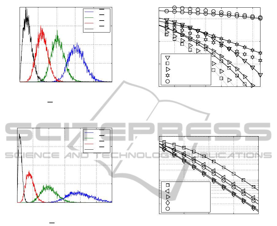
4 RESULTS
In this contribution fixed transmission modes are
used regardless of the channel quality. Assum-
ing predefined transmission modes, a fixed data rate
can be guaranteed. Considering a frequency non-
selective SDM (spatial division multiplexing) single-
user MIMO link (K = 1) composed of n
T
= 4 transmit
and n
R
= 4 receive antennas, the obtained BER curves
are depicted in Fig. 2 for the different QAM con-
stellation sizes and MIMO configurations of Tab. 1,
when transmitting at a bandwidth efficiency of 8
bit/s/Hz. Assuming a uniform distribution of the
transmit power over the number of activated MIMO
layers, it turns out that not all MIMO layers have to
be activated in order to achieve the best BERs.
PA can be used to balance the bit-error probabili-
ties in the differentnumber of activated MIMO layers.
As shown in Fig. 2, unequal PA is only effective in
conjunction with the optimum number of MIMO lay-
ers and at high SNR. Using all MIMO layers, our PA
scheme would assign much of the total transmit power
to the specific symbol positions per data block having
the smallest singular values and hence the overall per-
formance would deteriorate.
Analyzing an uncorrelated (4 ×4) MIMO chan-
nel, the corresponding distribution of the singular-
values is depicted in Fig. 3. Besides, assuming a
transmit antenna separation of 10-wavelength and a
receive antenna separation of 4-wavelength at a car-
rier frequency of 2.4 GHz, the resulting distribution
of the singular-values within the correlated MIMO
system is depicted in Fig. 4. Comparing the dis-
tribution of the singular-values depicted in Fig. 3 and
4, the correlation shifts the pdf (probability density
PECCS 2011 - International Conference on Pervasive and Embedded Computing and Communication Systems
336
0 1 2 3 4 5
0
0.005
0.01
0.015
0.02
p
ξ
1
p
ξ
2
p
ξ
3
p
ξ
4
pdf →
singular value →
Figure 3: PDF (probability density function) of the layer-
specific amplitudes
p
ξ
ℓ
for uncorrelated frequency non-
selective MIMO channels.
0 1 2 3 4 5 6
0
0.01
0.02
0.03
0.04
p
ξ
1
p
ξ
2
p
ξ
3
p
ξ
4
pdf →
singular value →
Figure 4: PDF (probability density function) of the layer-
specific amplitudes
p
ξ
ℓ
for correlated frequency non-
selective MIMO channels.
function) of the largest singular-value to higher val-
ues at the cost of the remaining layers. Thus, taking
the correlated MIMO channel instead of the uncorre-
lated one into consideration, we observe that the in-
fluence of the layer with the largest weighting factor
increases. Since the performance of a MIMO trans-
mission is strongly affected by the smallest singular
values of the channel matrix, the statistical distribu-
tion of the smallest singular values is of great impor-
tance for the characterization of a MIMO transmis-
sion scheme. In consequence, as the ratio between
the largest and smaller singular-value increases as the
correlation between antennas increases, it is expected
that the resulting BER increases with respect to the
uncorrelated case. Thus, since the pdf dispersion of
the singular values changes, the best uncoded solution
for the uncorrelated MIMO channel doesn’t necessar-
ily lead to the best solution for the correlated one. The
obtained BER curvesare depicted in Fig. 5 for the dif-
ferent QAM constellation sizes and MIMO configura-
12 14 16 18 20 22 24
10
−8
10
−6
10
−4
10
−2
10 ·log
10
(E
s
/N
0
) (indB) →
bit-error rate →
(256,0,0, 0) QAM
(64,4,0,0) QAM
(16,16,0, 0) QAM
(16,4,4,0) QAM
(4,4,4,4) QAM
Figure 5: BER with PA (dotted line) and without PA (solid
line) when using the transmission modes introduced in
Tab. 1 and transmitting 8 bit/s/Hz over correlated frequency
non-selective channels.
10 15 20 25 30
10
−3
10
−2
10
−1
10 ·log
10
(E
s
/N
0
) (indB) →
bit-error rate →
(256,0,0, 0) QAM
(64,4,0,0) QAM
(16,16,0, 0) QAM
(16,4,4,0) QAM
(4,4,4,4) QAM
Figure 6: SVD-based user-specific BERs without PA when
using the transmission modes introduced in Table 1 and
transmitting 8 bit/s/Hz over uncorrelated frequency non-
selective channels.
tions of Tab. 1, when transmitting at a bandwidth ef-
ficiency of 8 bit/s/Hz. Here, the joint optimization of
the number of activated MIMO layers along with the
appropriate allocation of the transmit power allows us
to minimize the overall BER under the constraint of a
given fixed data throughput efficiently.
The parameters of the exemplarily studied two-
users MIMO system are chosen as follows: P
sk
=
1V
2
, n
Rk
= 4 (with k = 1,2), K = 2,n
R
= n
T
=
8. In this contribution a power with the dimension
(voltage)
2
(in V
2
) is used. At a real, constant resis-
tor this value is proportional to the physical power (in
W). The obtained user-specific BER curves are de-
picted in Fig. 6 for the different QAM constellation
sizes and MIMO configurations of Tab. 1 and con-
firm the obtained results within the single-user sys-
tem (K = 1). Assuming a uniform distribution of the
MODULATION-MODE ASSIGNMENT FOR SVD-ASSISTED MULTIUSER MIMO SYSTEMS WITH
CORRELATION
337
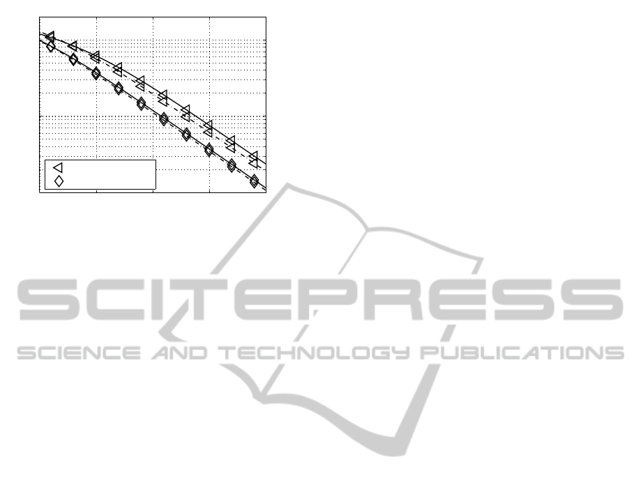
10 15 20 25 30
10
−3
10
−2
10
−1
10 ·log
10
(E
s
/N
0
) (indB) →
bit-error rate →
(64,4,0,0) QAM
(16,4,4,0) QAM
Figure 7: User-specific BERs with PA (dashed line) and
without PA (solid line) when using the transmission modes
introduced in Table 1 and transmitting 8 bit/s/Hz over un-
correlated frequency non-selective channels.
transmit power over the number of activated MIMO
layers, it still turns out that not all MIMO layers have
to be activated in order to achieve the best BERs. PA
can be used to balance the bit-error probabilities in the
activated MIMO layers. The obtained BER curves are
depicted in Fig. 7 and show, based on the chosen DL
preprocessing design, only minor improvements by
using adaptive PA within the investigated multiuser
MIMO transmission scheme. Here, an equal power
distribution seems to be a good choice.
5 CONCLUSIONS
Single- and multiuser MIMO systems in conjunc-
tion with SVD-assisted signal processing were inves-
tigated in this work. It turned out, that the choice of
the number of bits per symbol as well as the num-
ber of activated MIMO layers substantially affects
the performance of a MIMO system, suggesting that
not all MIMO layers have to be activated in order to
achieve the best BERs. The main goal was to find
that specific combination of the QAM mode and the
number of MIMO layers, which gives the best possi-
ble BER performance at a given fixed bit/s/Hz band-
width efficiency. The E
s
/N
0
value required by each
scheme at BER 10
−2
was extracted from computer
simulations and the best systems are shown in bold in
Table 1. Moreover, it has been shown that the antenna
correlation strongly affects the system performance.
Here, the performed joint optimization of the number
of activated MIMO layers along with the appropriate
allocation of the transmit power allows us efficiently
to minimize the overall BER under the constraint of a
given fixed data throughput.
REFERENCES
Ahrens, A. and Benavente-Peces, C. (2010). Modulation-
Mode and Power Assignment for SVD-assisted and
Iteratively Detected Downlink Multiuser MIMO Sys-
tems. In International Conference on Wireless Infor-
mation Networks and Systems (WINSYS), pages 107–
114, Athens (Greece).
Ahrens, A. and Lange, C. (2008). Modulation-Mode and
Power Assignment in SVD-equalized MIMO Sys-
tems. Facta Universitatis (Series Electronics and En-
ergetics), 21(2):167–181.
Choi, R. L. and Murch, R. D. (2003). New Transmit
Schemes and Simplified Receivers for MIMO Wire-
less Communication Systems. IEEE Transactions on
Wireless Communications, 2(6):1217–1230.
Choi, R. L. and Murch, R. D. (2004). A Transmit Prepro-
cessing Technique for Multiuser MIMO Systems us-
ing a Decomposition Approach. IEEE Transactions
on Wireless Communications, 3(1):20–24.
Durgin, G. D. and Rappaport, T. S. (1999). Effects of Multi-
path Angular Spread on the Spatial Cross-Correlation
of Received Voltage Envelopes. In IEEE Vehicu-
lar Technology Conference (VTC), pages 996–1000,
Houston, Texas, USA.
Joham, M., Utschick, W., and Nossek, J. A. (2005). Lin-
ear Transmit Processing in MIMO Communications
Systems. IEEE Transactions on Signal Processing,
53(8):2700–2712.
K¨uhn, V. (2006). Wireless Communications over MIMO
Channels – Applications to CDMA and Multiple An-
tenna Systems. Wiley, Chichester.
Liu, W., Yang, L. L., and Hanzo, L. (2008). SVD Assisted
Joint Transmitter and Receiver Design for the Down-
link of MIMO Systems. In IEEE 68th Vehicular Tech-
nology Conference (VTC), pages 1–5, Calgary.
Meurer, M., Baier, P. W., Weber, T., Lu, Y., and Papathanas-
siou, A. (2000). Joint Transmission: An Advanta-
geous Downlink Concept for CDMA Mobile Radio
Systems using Time Division Duplexing. Electronics
Letters, 36(10):900–901.
Proakis, J. G. (2000). Digital Communications. McGraw-
Hill, Boston.
Zelst, A. v. and Hammerschmidt, J. S. (2002). A Single Co-
efficient Spatial Correlation Model for Multiple-Input
Multiple-Output (MIMO) Radio Channels. In 27th
General Assembly of the International Union of Ra-
dio Science, Maastricht.
PECCS 2011 - International Conference on Pervasive and Embedded Computing and Communication Systems
338
