PROTECTION OF 3D OBJECTS AGAINST ILLEGAL
PHOTOGRAPHY USING OPTICAL WATERMARKING
TECHNIQUE WITH SPATIALLY MODULATED
ILLUMINATION
Yasunori Ishikawa, Kazutake Uehira and Kazuhisa Yanaka
Kanagawa Institute of Technology, Atsugi-shi, Japan
Keywords: Watermarking, 3D objects, Spatially modulated illumination.
Abstract: We present a new technique that protects the copyrights or portrait rights of 3D objects such as sculptures,
merchandise, and even human bodies, with optical watermarking, which is produced by spatially modulated
illumination. Although the previous study revealed that the optical watermarking technique could prevent
objects from being illegally photographed without protection, the technique could only be applied to 2D
objects. The largest problem to be solved in extending this technique to the case of 3D objects is to
compensate for geometrical distortion. We solved this problem by introducing rectangular mesh fitting and
a technique of "bi-linear interpolation" based on the four nearest points. We conducted experiments in
which we projected optical watermarking onto the surface of a globe and a model of the human face, and
evaluated the accuracy of extracted data. The results were almost 100% in both cases when a Discrete
Cosine Transform (DCT) and a Walsh-Hadamard Transform (WHT) were used as methods of embedding
watermarks.
1 INTRODUCTION
Techniques of digital watermarking have been
widely recognized in recent years as methods of
protecting the copyrights of digital image content.
For example, digital watermarking is embedded in
digital data before it is printed to protect paper
images. This is the same as for other types of digital
media. However, this method cannot prevent
photographs of valuable paintings at museums and
galleries from being illegally taken with digital
cameras.
We have proposed a novel technology that can
prevent the illegal use of images of objects that do
not have watermarking, using illumination with
invisible watermarking. We carried out experiments
and revealed that watermarking data were read out
with almost 100% accuracy. In this paper we
propose the optical watermarking technology
applying to real 3D objects like sculptures in
museums, merchandise in stores, or even human
bodies on stages.
Figure 1: Basic concept underlying proposed technology.
49
Ishikawa Y., Uehira K. and Yanaka K..
PROTECTION OF 3D OBJECTS AGAINST ILLEGAL PHOTOGRAPHY USING OPTICAL WATERMARKING TECHNIQUE WITH SPATIALLY
MODULATED ILLUMINATION.
DOI: 10.5220/0003314400490052
In Proceedings of the International Conference on Imaging Theory and Applications and International Conference on Information Visualization Theory
and Applications (IMAGAPP-2011), pages 49-52
ISBN: 978-989-8425-46-1
Copyright
c
2011 SCITEPRESS (Science and Technology Publications, Lda.)
2 WATERMARKING
TECHNIQUE APPLYING
TO BASIC 2D OBJECTS
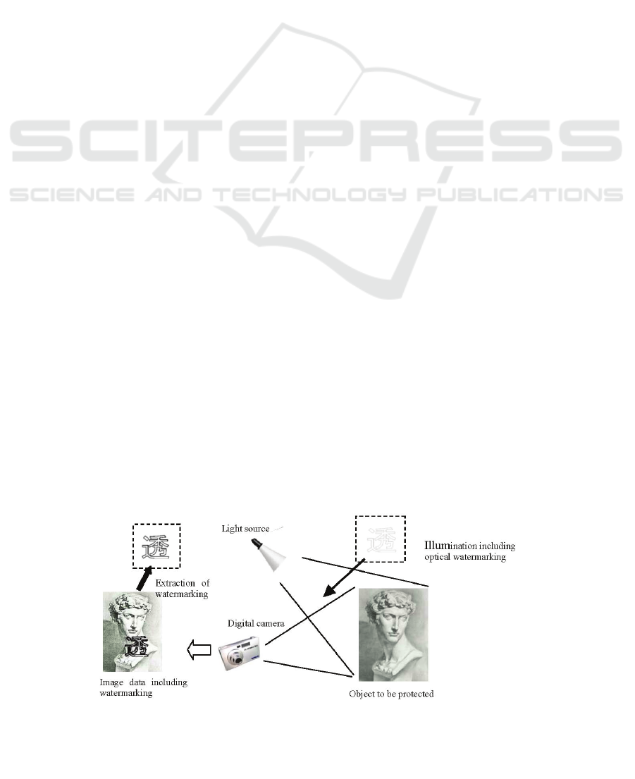
Fig. 1 outlines the basic concept underlying the
optical watermarking technology. A projector is
possibly used as the light source that contains the
watermarking information and illuminates an object.
The brightness of the object's surface is proportional
to the product of the reflectance of the surface and
the illumination by the light source.
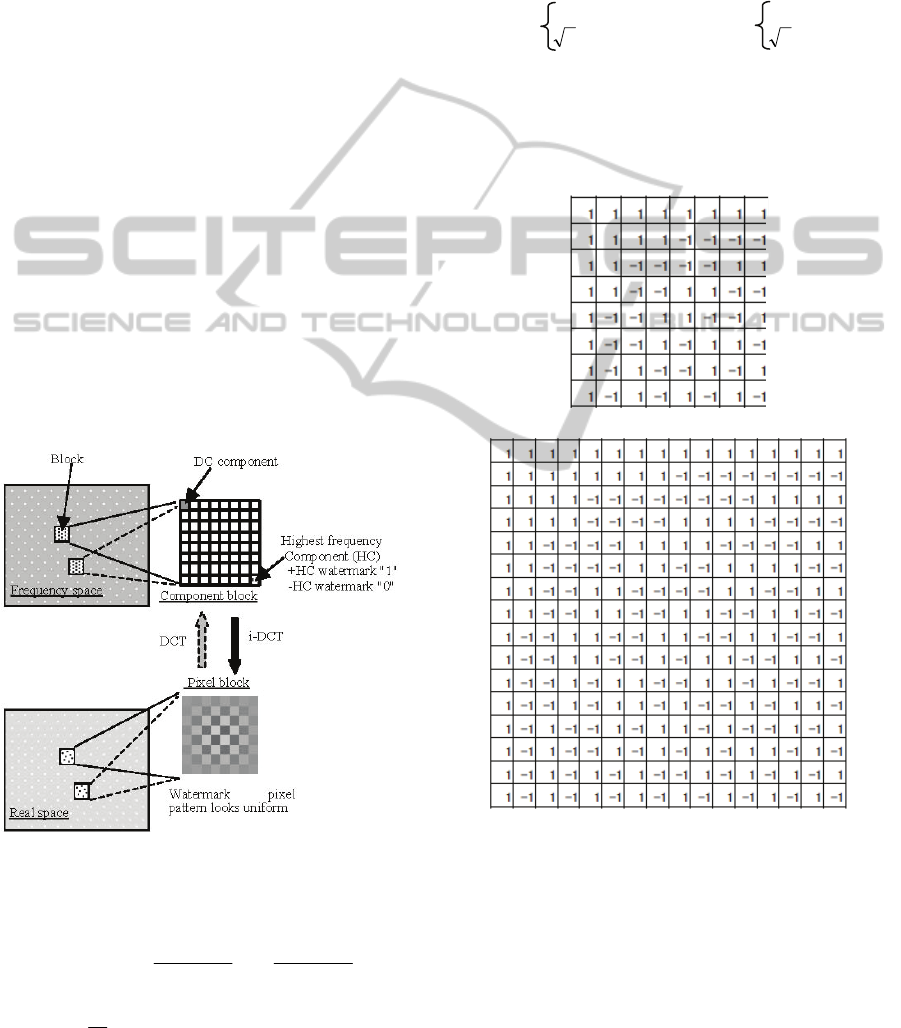
Fig. 2 illustrates the procedure for watermarking
using orthogonal transforms. The watermarking area
is divided into units of 16×16 or 8×8 pixel blocks,
and each block has a DC component that gives an
average brightness for the entire watermarking area,
i.e., the brightness of illumination. Every block also
has the highest frequency component (HC) in both
the
x
- and
y
- directions to express the 1-bit binary
information for watermarking. The phase of HC was
used to express binary data i.e., "0" or "1". Other
components than DC or HC were set to "0". DCT
and WHT were used as orthogonal transforms to
produce the watermarking images. The equations of
i-DCT and i-WHT are expressed with Eq. (1) and Eq.
(2) respectively.
Figure 2: Producing watermarks.
1
,
1
,
),()()(),(
N
u
ji
N
v
ji
vuFvCuCyxf
(1)
}
2
)12(
cos{}
2
)12(
cos{
N
vy
N
ux
11
,,
1
(, ) (,) (,) (, )
NN
ij ij
uv
f
xy F uvwhxuwhvy
N
(2)
where
),(
,
yxf
ji
are the watermarking image data for
pixel
),( yx
of block
),( ji
in real space,
),(
,
vuF
ji
are
the data for component
),( vu
of block
),( ji
in
frequency space, and
N
is the number of pixels in
the block in the
x
- and
y
-directions. Here,
)(uC
and
)(vC
are given as
)0(2
)0(1
)(
u
u
uC
,
)0(2
)0(1
)(
v
v
vC
,
and
),( jiwh
denotes a component of the Walsh-
Hadamard matrix in Table 1.
Table 1: Walsh-Hadamard Matrix.
(a) 8×8 Matrix
(b) 16×16 Matrix
3 APPLYING TO 3D OBJECT
First, the grid pattern image that divides the region
of the optical watermarking equally into 8 × 8 is
irradiated onto the object image and captured with a
digital camera to apply optical watermarking
technique to 3D objects. The coordinates of the
corner points of the segmented areas are measured
IMAGAPP 2011 - International Conference on Imaging Theory and Applications
50

respectively on the captured image data. Then, the
image data irradiated with optical watermarking are
captured, and these are corrected by using the
coordinates of the corner points of the segmented
area as each segmented region may become a precise
square.
The transformation from an undistorted coordinate
system
),( yx
to a geometrically distorted system
)','( yx
is generally expressed by following
equations.
),('
1
yxhx
,
),('
2
yxhy
(3)
If the distortion is perspective, the transformation is
expressed by the following linear equations.
cbyaxx '
,
feydxy
'
(4)
Using these equations the value of pixels in the
distorted quadrangle can be transformed to the value
of pixels in the undistorted rectangle. However,
because the coordinates of transformed pixels do not
generally become integers, an interpolation
technique is utilized to determine the density value
of the nearest pixel. Linear transformation using the
four nearest neighboring pixels was used in the
experiments, which is so called "bi-linear
interpolation".
4 EXPERIMENTS
Watermarking images had 128 × 128 pixels that
consisted of 16 × 16 blocks of 8 × 8 pixels in the
experiments. A Digital Light Processing (DLP)
projector that had a resolution of 800 × 600 pixels
was used as a light source. A white hemisphere, a
globe, and a model of a human face were used as
real 3D objects. Fig. 3. (a) shows the image of a
globe irradiated with the grid pattern, and Fig. 3. (b)
and (c) have the photographs of the human-face
model onto which the watermarking or grid pattern
was projected.
Using the measured coordinates of the grid
points, each 8 × 8 divided segments were identified
and were corrected to a precise rectangle as
described in the previous section. The restored
rectangular area had about 650 × 650 pixels using a
digital camera with a resolution of 4288 × 2848
pixels. It was transformed to 256 × 256 pixels and
divided into 16 × 16 blocks. We carried out DCT on
all blocks using Eq. (5).
11
,,
),(
)()(
),(
M
x
M
y
jiji
yxf
MM
vCuC
vuF
}
2
)12(
cos{}
2
)12(
cos{
M
vy
M
ux
(5)
We also utilized Eq. (6) for WHT, using the values
in Table 1(b) as the components of matrix
),( jiwh
and
16
M
.
11
,,
1
(,) (, ) (,) (,)
MM
ij ij
xy
F
uv f xywhuxwhyv
M
(6)
The accuracy of reading out the embedded data was
evaluated by checking the sign of the
)7,7(
, ji
F
components for all blocks. Two methods of
embedding data were used. The "1-block method"
involved embedding 1-bit data into one block and
embedding 256 1-bit binary data into 16 × 16 blocks.
The "majority method" involved embedding the
same 1-bit data into three blocks sufficiently
separated from one another, and the readout data
were determined by the majority decision. The
distance between the blocks was set to five and 75 1-
bit binary data were embedded in 16 × 16 blocks in
the experiments.
(a) Grid pattern on a globe (b) Human-face model (c) Magnified image of the grid
pattern on a human-face model
Figure 3: Photographs of a globe and a human-face model on which image was projected.
PROTECTION OF 3D OBJECTS AGAINST ILLEGAL PHOTOGRAPHY USING OPTICAL WATERMARKING
TECHNIQUE WITH SPATIALLY MODULATED ILLUMINATION
51

Table 2: Experimental results: Accuracy with which embedded data were read out.
HC →
5 7 10 15 20 25 5 7 10 15 20 25
white-ball 111111111111
globe-1 0.964 0.964 0.964 0.966 0.982 0.996 110.987 111
globe-2 0.996 0.996 1111111111
face-1 1 0.996 0.991 111111111
face-2 111111111111
white-ball 111111111111
globe-1 0.969 0.987 0.991 0.982 0.996 1111111
globe-2 111111111111
face-1 111111111111
face-2 111111111111
WHT
1-block method Majority method
DCT
5 RESULTS AND DISCUSSION
Table 2 lists the overall results of experiments. In the
table "white-ball" means that a white hemisphere
was used as 3D object. In the same way, "globe-1"
means European-African hemisphere of a globe was
used, "globe-2" means Pacific-Ocean hemisphere of
a globe was used, "face-1" means cheek of a human-
face model was used and "face-2" means forehead of
a human-face model was used. The results of
evaluating accuracy for the white hemisphere had
100% under all conditions with DCT and WHT.
However, 100% accuracy was not achieved in
evaluating accuracy with the globe, especially in the
European-African hemisphere, where the 1-bit block
method was used with DCT and WHT. The decision
by using the majority method achieved an accuracy
of 100% excluding the HC=10 of DCT. The
European-African hemisphere has numerous black
lines and characters and these could disturb the
accuracy of reading out embedded data.
An accuracy of 100% for the evaluation of the
human-face model was obtained under all conditions
in the decision by the majority method. The 1- block
method achieved an accuracy of 100% excluding
part of the DCT. The surface of the human-face
model was painted white in this experiment, and the
reflectivity of the surface may have been
proportional to the brightness of the irradiated
optical watermarking.
6 CONCLUSIONS
We proposed the application of optical watermarking
to 3D objects, which can prevent real objects like
sculptures in museums from being illegally
photographed. We used methods of correcting
distortions in captured images caused by projecting
optical watermarking image onto the curved surface
of objects. We found that the embedded data were
read out with almost 100% accuracy when DCT and
WHT were used for embedding watermarking, after
distortions in the captured images had been
corrected. In this paper we used a projected grid
pattern to indicate the correct pixel block, prior to
the images for embedding watermarking being
captured. However, if the marker that appropriately
identifies pixel blocks is simultaneously embedded
into optical watermarking images, it can easily be
extracted with image processing. Therefore, we
demonstrated the feasibility of using optical
watermarking technique to protect real 3D objects
from being illegally captured which has been
difficult to accomplish with conventional
watermarking technology.
REFERENCES
Mizumoto, T. and Matsui, K. 2002. Robustness
investigation of DCT digital watermark for printing
and scanning. Trans. IEICE (A), J85-A(4), 451-459.
Uehira, K. and Suzuki, K. 2008. Digital watermarking
technique using brightness-modulated light. Proc.
ICME2008, 257-260.
Ishikawa, Y., Uehira, K. and Yanaka, K. 2009.
Illumination watermarking technique using orthogonal
transforms. Proc. IAS2009, 257-260.
Kishk, S. and Javidi, B. 2003. 3D object watermarking by
a 3D hidden object. OPTICS EXPRESS, 11(8), 874-
888.
Bennour, J. and Dugelay, J. L. 2006. Protection of 3D
object through silhouette watermarking. Proc. ICASSP
2006.
Rosenfeld, A. and Kak, A. C. 1979. Digital Picture
Processing (pp. 175-179). New York: Academic Press.
IMAGAPP 2011 - International Conference on Imaging Theory and Applications
52
