
TOOL PATH PLANNING IN FLANK MILLING BASED ON DUAL
SPHERICAL SPLINE
Yayun Zhou
Siemens AG, CT T DE TC3/GTF MSO, Otto-Hahn-Ring 6, 81739 Munich, Germany
J
¨
org Schulze
Universit
¨
at Stuttgart, Pfaffenwaldring 47, 70569 Stuttgart, Germany
Stefan Sch
¨
affler
Universit
¨
at der Bundeswehr M
¨
unchen, Werner-Heisenberg-Weg 39, 85577 Neubiberg, Germany
Keywords:
Ruled surface, Blade design, Flank milling, Dual spherical spline.
Abstract:
The flank milling (side milling) method, which uses the manufacturing tool side to remove material, is widely
used in industry to manufacture ruled surfaces. Ruled surfaces are often used in blade design considering the
aerodynamics requirements and the manufacture cost. A common way to derive a flank millable blade surface
is to adopt a certain ruled surface approximation algorithm before the surface is delivered to the manufacturer.
In this paper, a new tool path planning approach is proposed based on the offset theory and the kinematic ruled
surface approximation. The novelty of this approach is to denote the drive surface as a dual spherical spline,
which is a new ruled surface representation. This drive surface is derived by kinematically approximating the
offset surface of the original design as a ruled surface. Therefore, the designed blade surface is represented as
a flank milling tool path with a cylindrical cutter in CNC machining. This approach delivers more accuracy
compared with convectional tool position optimization methods. By integrating the manufacture requirements
into the design phase, this approach also reduces the developing cycle time and the manufacturing cost.
1 INTRODUCTION
Considering the aerodynamics requirements and the
manufacturing cost, blade surfaces are usually de-
signed as ruled surfaces, which are a special type of
surfaces that can be generated by moving a line in
space. In industry, the flank milling method is of-
ten used to machine ruled surfaces. Different from
the face milling (point milling) method, flank milling
(side milling) uses the side of the manufacturing tool
instead of the tip of the manufacturing tool to touch
the surface and remove the stock in front of the cut-
ter. Since the whole length of the cutter is involved
in the cutting process, this method has high mate-
rial removal rate and high machining efficiency. Be-
sides, no scallops are left behind in single pass flank
milling, less surface finishing work is required. Espe-
cially for the manufacturing of a turbocharger com-
pressor/impeller, it is necessary to use 5-axis flank
milling, because the tunnel between two adjacent
blades is too small with respect to the size of blades.
Hence, designing a flank millable blade is appealing
in many fields.
A common way to derive a flank millable blade
surface is to adopt a certain ruled surface approxi-
mation algorithm before the surface is delivered to
the manufacturer. Theoretically, if the manufactur-
ing tool is considered as a line, a ruled surface can be
accurately produced by moving this line. However,
the machine tool usually has certain size and shape
(i.e., cylindrical cutter or conical cutter), so the ideal
position for the cutting tool is to offset the ruling in
the direction of a surface normal at a distance equal
to the radius of the cutting tool. Because the surface
normals rotate along the ruling, at some point the cut-
ting tool will begin to deviate from the desired sur-
face. Generally, the machined surface is not a ruled
surface, but a curved surface. At each tool position,
the effective contact between the cutting tool and the
swept surface is a curve (grazing curve), not a straight
line.
Researchers developed a variety of cutter location
5
Zhou Y., Schulze J. and Schäffler S..
TOOL PATH PLANNING IN FLANK MILLING BASED ON DUAL SPHERICAL SPLINE.
DOI: 10.5220/0003274600050012
In Proceedings of the International Conference on Computer Graphics Theory and Applications (GRAPP-2011), pages 5-12
ISBN: 978-989-8425-45-4
Copyright
c
2011 SCITEPRESS (Science and Technology Publications, Lda.)
(CL) data optimization methods to minimize the man-
ufacturing error. The simplest way is to locate a cylin-
drical cutting tool tangentially to the given surface at
one point on the ruling and make the tool axis parallel
to the ruling. Alternatively, the tool can also be posi-
tioned to touch two points on the ruling. Both ideas
belong to the direct tool position method (Liu, 1995).
An improvement of the direct tool position method
is to locate the tool step by step (Choi et al., 1993)
(Menzel et al., 2004). In those approaches, the initial
position of the cutting tool is determined by one of
the direct tool position methods, afterwards the tool
is lifted and twisted in order to reduce the manufac-
turing error. The computation time of the step by step
method is usually long. The third type of tool posi-
tioning method combines the techniques used in the
two classes above. The tool contacts three points on
the given surface (two on the guiding curves and one
on the ruling). Those three points are obtained by
solving seven transcendental equations based on cer-
tain geometrical conditions (Redonnet et al., 1998).
However, those methods all focus on the local er-
ror reduction corresponding to each tool location. The
kinematic error between successive CL points can
still be large. In order to get a global optimal tool path,
a new type of approach is developed (Gong et al.,
2005) (Chu and Chen, 2006) (Senatore et al., 2008)
(Zhou et al., 2009). The authors propose a global op-
timization method to generate the tool axis trajectory
surface which is also a ruled surface. The cutting tool
is positioned so that the maximum deviation between
the tool axis trajectory surface and the offset surface
is minimized. The trajectory surface of the tool axis
(drive surface) is often represented as a tensor prod-
uct B-spline surface, therefore each tool position is
determined.
In this paper, we propose a new strategy to repre-
sent the drive surface as a dual spherical spline (Zhou
et al., 2010), in which every ruling of the ruled surface
is written as a dual vector. It indicates the orientation
of the tool axis with respect to a specific point on the
workpiece and has the same mathematical represen-
tation of screws (Dimentberg, 1965). Using the dual
vector calculation rules, the tool axis position is eas-
ily converted to the tool motion. Compared with the
conventional tensor product B-spline surface repre-
sentation, it is more effective to specify a 5-axis CNC
machining tool path by relating both the position and
orientation to a single parameter. Based on this repre-
sentation, it is possible to check whether the desired
path is within the workspace of the machine tool by
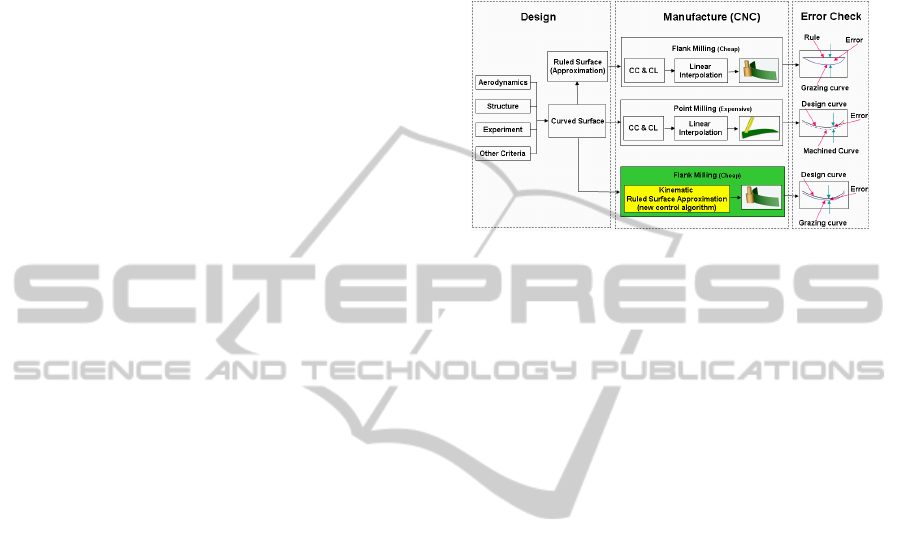
applying the kinematics and robotics analysis. Fig. 1
compares this new approach with the conventional de-
sign and manufacturing methods. The new approach
not only inherits the advantages of global path opti-
mization methods which ensure low manufacturing
cost and avoid introducing double errors, but also pro-
vides a novel representation which is closely linked to
the tool movement.
Figure 1: A comparison of different design and manufac-
turing diagram.
The organization of this paper is as follows. Sec-
tion 2 lays the theoretical basis of this approach, in-
cluding the offset theory and ruled surface represen-
tations. Then the definition of dual spherical spline is
briefly introduced and its advantages in motion con-
version are shown in Section 3. In Section 4, the drive
surface is derived from the offset surface of original
design based on a kinematic ruled surface approxi-
mation algorithm. This algorithm can be modified to
embrace more manufacture constrains corresponding
to difference CNC machines. This approach is tested
with some given turbocharger blade surfaces. The
simulation results are presented in Section 5. Finally,
a conclusion is drawn in Section 6.
2 THEORETICAL BASIS
The approach proposed in this paper mainly contains
two key steps: first deriving an offset surface from the
original design, then generating a drive surface from
the offset data. The drive surface is a ruled surface,
which is denoted as a dual spherical spline. In this
section, the offset theory and representations of ruled
surface are introduced.
2.1 Offset Theory
If R(u) = R(u
1
, u
2
) represents a surface, its offset
surface R
o
(u) is defined by the equation (Marciniak,
1991):
R
o
(u) = R(u) + d ·n(u), (1)
where n is a normal vector in R(u) and d is the dis-
tance between the surfaces. This is the classical offset
GRAPP 2011 - International Conference on Computer Graphics Theory and Applications
6

surface definition. It is also referred to as parallel off-
set. In (Pottmann et al., 1996), Pottmann and L
¨
u study
the “circular offset” of ruled surfaces, which arises
when a cylindrical or conical cutter with a circular
edge is used in flank milling. The authors proved that
the circular offsets of a rational ruled surface are ra-
tional in general except the developable surfaces and
conoidal ruled surfaces with generators orthogonal to
the tool-axis. The offset of a ruled surface is in gen-
eral not a ruled surface. In fact, the offset curve of a
nontorsal generator with respect to a ruled surface is
a rational quadric (Pottmann et al., 1996).
For ruled surfaces, we often meet the concept
Bertrand offset. It is a generalization of the theory
of Bertrand curves based on line geometry. A pair of
curves are Bertrand mates if there exists a one-to-one
correspondence between their points such that both
curves share a common principal normal at their cor-
responding points (Ravani and Ku, 1991). Consid-
ering the ruled surface in the context of line geome-
try, the ruled surface is represented as a one-parameter
family of lines. Simply speaking, we have the follow-
ing definition (Ravani and Ku, 1991):
Definition 2.1. Two ruled surfaces are said to be
Bertrand offsets of one another if there exists a one-to-
one correspondence between their rulings such that
both surfaces have a common principal normal at the
striction points of their corresponding rulings.
For the Bertrand offsets, we have an important
theorem (Ravani and Ku, 1991):
Theorem 2.1. Two ruled surfaces which are Bertrand
offsets of each other as defined in Definition 2.1 are
constant offsets of one another.
Inspired by this theorem, if the given surface is
a ruled surface, the drive surface can be derived by
constructing the Bertrand offset of the given surface.
Consequently, the given surface is also a Bertrand off-
set surface of the drive surface. This relationship pro-
vides the initial inspiration of our approach. Gener-
ally, the original designed surface is not a ruled sur-
face. In our algorithm, we calculate the “circular off-
set” of the given surface instead.
2.2 Ruled Surface Representations
In Euclidean space R
3
, a ruled surface Φ possesses a
parametric representation (Edge, 1931):
x(u, v) = a(u) + vr(u), u ∈ I, v ∈ R, (2)
where a(u) is called the directrix curve and r(u)
is a direction vector of generator. Alternatively, a
ruled surface Φ can be parameterized by two direc-
trix curves p(u) and q(u):
x(u, v) = (1 −v)p(u) + vq(u). (3)
The straight line denoted as x(u
0
, v) = (1 −v)p(u
0
)+
vq(u
0
) is called a ruling.
By applying the Klein mapping and the Study
mapping, a ruled surface can be written in a more
compact way using dual numbers. The dual numbers
were first introduced by Clifford (Clifford, 1873). A
dual number can be written in the form ˆa = a + εa
◦
,
where a, a
◦
∈ R and ε is the dual element with:
ε 6= 0,
0ε = ε0 = 0,
1ε = ε1 = ε,
ε
2
= 0.
(4)
Extending the dual numbers to the vector space,
the space D
3
is defined as a set of all pairs of vectors:
ˆ
a = a + εa
◦
where a, a
◦
∈ R
3
. (5)
In line geometry, a line in Euclidean space can
be represented as a unit vector in D
3
(Pottmann and
Wallner, 2001). Those unit vectors constitute a sphere
called Dual Unit Sphere (DUS). In this form, a ruled
surface defined by Eq. (2) is written as a curve on the
DUS :
ˆ
L(u) = l(u) + εl
◦
(u) =
r(u)
kr(u)k
+ ε
a(u) ×r(u)
kr(u)k
. (6)
A dual vector representation of ruled surface can
be converted to a point representation:
x(u, v) = l(u) ×l(u)
◦
+ vl(u). (7)
Now, a mapping between a ruled surface represen-
tation in Euclidean space and a curve representation
on the DUS is set up. Instead of solving a surface ap-
proximation problem in the Euclidean space, we solve
a curve approximation problem on the DUS.
3 DEFINITION OF DUAL
SPHERICAL SPLINE
The dual vector representation of ruled surface
links the path and the physical motion of the tool
(Sprott and Ravani, 1997) (Sprott and Ravani, 2001).
K. Sprott proposed an algorithm to generate a free-
form curve on the DUS (Sprott, 2000), but defining
a spline strictly lying on the DUS is not trivial. Due
to the non-linearity of the space, conventional spline
definitions as a linear combination of basis functions
are not working on the DUS.
3.1 Dual Spherical Spline
The definition of dual spherical spline is inspired by
(Buss and Fillmore, 2001), in which a spline on a real
TOOL PATH PLANNING IN FLANK MILLING BASED ON DUAL SPHERICAL SPLINE
7

sphere is defined based on a least squares minimiza-
tion. Based on the transfer principle, which simply
states that for any operation defined for a real vector
space, there is a dual version with similar interpreta-
tion, we can derive a similar definition of a spline on
the DUS:
Definition 3.1. Let
ˆ
p
1
, . . . ,
ˆ
p
n
be control points on the
Dual Unit Sphere
ˆ
S
2
in D
3
: a spline on the DUS is
defined as a result of a least squares minimization. In
other words, it contains the points
ˆ
s(t) on
ˆ
S
2
which
minimizes the value:
ˆ
f (
ˆ
s(t)) =
1
2
∑
i
ω
i
·dist
S
(
ˆ
s(t),
ˆ
p
i
)
2
, (8)
where dist
S
(
ˆ
s(t),
ˆ
p
i
) is the dual spherical distance be-
tween
ˆ
s(t) and
ˆ
p
i
. This spline on the DUS is denoted
as a dual spherical spline:
ˆ
s(t) =
f
∑
n
i=1
f
i
(t)
ˆ
p
i
. (9)
The distance between two points on the DUS is
defined by a dual angle between two lines. It has the
form
ˆ
θ = θ + εd, where θ is the angle between the
lines and d is the minimum distance along the com-
mon perpendicular. For two points
ˆ
x and
ˆ
y on the
DUS, we have the following equation:
ˆ
x ·
ˆ
y = cos
ˆ
θ. (10)
The dual arc cosine function is defined as:
ˆ
θ = cos
−1
(x + εx
◦
) = cos
−1
(x) −ε
x
◦
√
1 −x
2
. (11)
The basis functions of a dual spherical spline must
always satisfy the property:
n
∑
i=1
f
i
(t) = 1, f
i
(t) ≥ 0 ∀i, (12)
for t in the interval [a, b].
Since Bernstein polynomials and B-spline basis
functions both satisfy the requirement Eq. (12), the
dual spherical B
´
ezier curve or B-spline curve
ˆ
s(t) can
be defined in the form of Eq. (9).
It is proven that there is a neighborhood of
ˆ
p
1
, . . . ,
ˆ
p
n
, in which the
ˆ
s(t) is a C
∞
-function of
ˆ
p
1
, . . . ,
ˆ
p
n
. Hence the regularity of the dual spheri-
cal spline is determined by the basis functions. The
proof of uniqueness and continuity property follows
the similar strategy as (Buss and Fillmore, 2001), the
details can be found in (Zhou, 2010).
3.2 Advantages in Motion Conversion
Now the drive surface, which is a ruled surface, is rep-
resented as a continuous, differentiable dual spherical
spline
ˆ
x(u). Following this definition, a local coordi-
nate frame can be set up consisting of three concurrent
lines – {
ˆ
x,
ˆ
n,
ˆ
t}. This frame is called generator trihe-
dron, where
ˆ
x represents a ruling and the other two
lines are defined by the following equations:
ˆ
t =
d
ˆ
x(u)
du
k
d
ˆ
x(u)
du
k
,
ˆ
n =
ˆ
x ×
ˆ
t.
(13)
The line
ˆ
t is called the central tangent, which is tan-
gent to the surface at the striction point. The line
ˆ
n
called central normal is the normal of the surface at
the striction point. It can be proven that these three
lines are orthogonal to each other and the intersection
point of the three lines is the striction point of the rul-
ing
ˆ
x. This point is the point of minimum distance
between neighboring rulings. The locus of striction
points is called the striction curve (Sprott and Ravani,
2007). The generator trihedron can be rewritten as
dual vectors:
ˆ
x = x + ε(a ×x),
ˆ
n = n + ε(a ×n),
ˆ
t = t + ε(a ×t),
(14)
where a is the striction point, x is a vector directing
along the ruling, the vector t is perpendicular to x and
tangent to the surface at the striction curve, the vector
n is perpendicular to x and t. Fig. 2 shows this frame
on a ruled surface. The center line of the cylindrical
cutter (a ruling of the drive surface) undergoes a screw
motion about the axis
ˆ
t. According to the screw the-
ory, the distance between successive rulings is defined
as a dual angle between two screws. The successive
rulings are denoted as
ˆ
x
1
=
ˆ
x(u
1
) =
f
∑
n
i=0
B
i, p
(u
1
)
ˆ
p
i
and
ˆ
x
2
=
ˆ
x(u
2
) =
f
∑
n
i=0
B
i, p
(u
2
)
ˆ
p
i
. The dual angle is
calculated by the following equations:
ˆ
x
1
·
ˆ
x
2
= cos
ˆ
ω = x + εx
◦
, (15a)
ˆ
ω = φ + εd
= cos
−1
( ˆx)
= cos
−1
(x + εx
◦
)
= cos
−1
(x) −ε
x
◦
√
1−x
2
.
(15b)
This means the cutter tool translates the distance
d and rotates the angle φ along the axis
ˆ
t in order to
move from position
ˆ
x
1
to position
ˆ
x
2
. The ratio be-
tween d and φ is called distribution parameter (Sprott,
2000):
p =
d
φ
. (16)
The distribution parameter indicates the amount of
twisting associated with the ruled surface. A cone
or tangent developable surface has a zero valued dis-
tribution parameter, while the distribution parameter
GRAPP 2011 - International Conference on Computer Graphics Theory and Applications
8
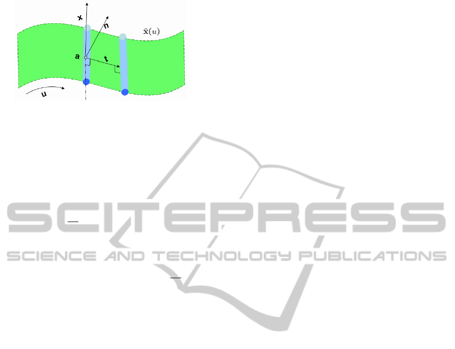
Figure 2: Generator trihedron on ruled surface.
of parallel rulings remains undefined. Generally, a
twisted ruled surface has a non-zero distribution pa-
rameter. If adopting time t as the parameter of the
dual spherical spline, it is quite easy to convert the
tool path to the motion code. The velocity of the line
is given by the expression:
d
ˆ
x
dt
=
˙
ˆ
x =
ˆ
ω ×
ˆ
x, (17)
where the angular velocity vector
ˆ
ω = ω + εv denotes
the rotation and translation along the screw axis
ˆ
t. In
this local coordinate frame, an arbitrary point P along
the ruling is written as P = sr, where r =
x
kxk
and s
is the distance from the striction point a. The velocity
of this point will have a term perpendicular to r due to
the rotation about the line
ˆ
t and a term in the direction
of
ˆ
t due to the translation along the line. The velocity
of the point can be written as (Sprott, 2000):
v
p
= ωt ×sr + vt
= −ωsn + vt.
(18)
4 TOOL PATH PLANNING
APPROACH
Based on the definition of dual spherical spline, a
kinematic approximation algorithm is developed to
construct a ruled surface from an offset surface. This
ruled surface is the drive surface. In this paper,
we propose a tool path planning approach for flank
milling with cylindrical tools. The framework of the
tool path planning approach contains four parts:
1. Generate an offset surface from the original de-
sign surface according to the tool radius
2. Extract the CL data from the offset surface and
write the coordinates as dual vectors
3. Apply the kinematic ruled surface approximation
algorithm
4. Evaluate the dual spherical B-spline with the dual
spherical weighted average algorithm and convert
it to tool motion
In this section, we briefly introduce the key steps of
this approach.
4.1 Offset Surface Generation and CL
Data Extraction
Initially, the blade surface is designed as a free-form
surface. In order to derive the cutter location (CL)
data, the original design is taken as an input and the
offset surface is derived according to Eq. 1. The dis-
tance d between the offset surface and the original de-
sign equals to the radius of the cylindrical tool. The
cutter locations are determined by a ruling search pro-
cess. It is to find a discrete system of line segments
close to the given surface. In order to fit the manu-
facture procedure, the search process starts from the
leading edge of the blade surface and marches to-
wards the trailing edge. The lines are chosen using
the least squares minimization method. The march
distance is constrained by the velocity of the milling
machine and most importantly, the intersection of the
line segments must be avoided. Other constrains of
manufacture machines can also influence the search
process. In the end of this step, a sequence of line
segments l
0
, . . . , l
N
are obtained which are close to the
given surface. The details of this step can be found in
(Chen and Pottmann, 1999).
4.2 Kinematic ruled Surface
Approximation
After the rulings are extracted and represented as dual
vectors, a kinematic ruled surface approximation al-
gorithm is applied to approximate the line sequences
as a ruled surface. The manufacture machine con-
strains should be included in the objective functional.
Due to the variety of manufacture systems, the main
task for this paper is to minimize the difference be-
tween the offset surface and drive surface. Its essence
is a dual spherical spline interpolation algorithm on
the DUS. In this paper, we take the dual cubic B-
spline interpolation algorithm as an example. It can
be easily extended to higher order B-splines.
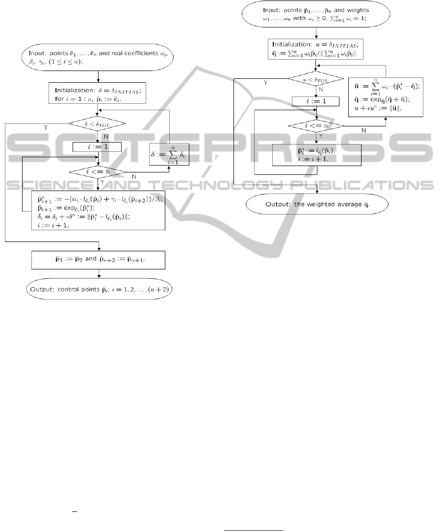
The key idea of this algorithm is to use the loga-
rithmic map which maps all points
ˆ
p
i
on the DUS to
the tangent hyperplane at
ˆ
q, then interpolate the points
in the hyperplane and maps the result back to the DUS
by the exponential map. As long as the given points
satisfy the uniqueness condition, the algorithm con-
verges. Fig. 3 shows the flowchart of the dual spher-
ical cubic B-spline interpolation algorithm, in which
the logarithmic map l
ˆ
q
(·) maps the point
ˆ
p
i
to the tan-
gent hyperplane at
ˆ
q and the exponential map exp
ˆ
q
(·)
maps the result back to the DUS. α
i
, β
i
, γ
i
denote the
TOOL PATH PLANNING IN FLANK MILLING BASED ON DUAL SPHERICAL SPLINE
9
non-zero elements in the basis matrix:
1 0 0 . . . 0 0
α
2
β
2
γ
2
0 . . . 0
0 α
3
β
3
γ
3
0
.
.
.
.
.
.
.
.
.
.
.
.
.
.
.
0
0 . . . 0 α
n−1
β
n−1
γ
n−1
0 0 . . . 0 0 1
. (19)
Figure 3: Flowchart of the dual spherical cubic B-spline
interpolation algorithm.
4.3 Dual Spherical Spline Evaluation on
the DUS
After the control points are derived, the dual spherical
B-spline is evaluated as weighted averages of control
points. The weighted average on the DUS is defined
similarly:
Definition 4.1. Let
ˆ
p
1
, . . . ,
ˆ
p
n
be points on the Dual
Unit Sphere
ˆ
S
2
in D
3
: a weighted average of these n
points using real weight values ω
1
, . . . , ω
n
such that
each ω
i
≥ 0 and
∑
ω
i
= 1 is defined as a result of a
least squares minimization. In other words, it is the
point
ˆ
C on
ˆ
S
2
which minimizes the value:
ˆ
f (
ˆ
C) =
1
2
∑
i
ω
i
·dist
S
(
ˆ
C,
ˆ
p
i
)
2
, (20)
where dist
S
(
ˆ
C,
ˆ
p
i
) is the dual spherical distance be-
tween
ˆ
C and
ˆ
p
i
. The weighted average on the DUS is
denoted as:
ˆ
C =
f
∑
n
i=0
ω
i
ˆ
p
i
. (21)
The flowchart of the algorithm calculating the
weighted average on the DUS is shown in Fig. 4.
Figure 4: Flowchart of the algorithm calculating the
weighted average on the DUS.
5 SIMULATION RESULT
We test this approach with different blade surfaces
and simulate the manufacturing process of a blade
with a cylindrical cutter. A blade consists of two
sides: pressure surface and suction surface. The tool
path planning strategies for both sides are similar.
Here, we only take one example to explain the pro-
cedure.
To achieve large material removal rate, the radius
of the cylinder should be large, but it must be less
than the distance between two blades. Therefore, for
different blades, the tool sizes are varied. For this test
case, the radius of the cylinder is chosen as R = 2 mm.
The input file is a “blade.ibl” file generated by a
software “Bladegen”. It contains discrete points on
blade surfaces. We first extract the data for the pres-
sure side of the blade. The offset surface is derived
based on Eq. (1) and d = R.
1
The simulation results of this approach are shown
in Fig. 5. Fig. 5(a) shows the given surface and its
offset surface. Fig. 5(b) shows the discrete cutter lo-
cations which are extracted from the offset surface.
1
An affine map is applied to the data due to confidential
requirements.
GRAPP 2011 - International Conference on Computer Graphics Theory and Applications
10

(a) (b)
(c) (d)
Figure 5: Design a flank millable turbocharger blade: (a)
Given blade surface (colored) and offset surface (red); (b)
CL data; (c) Movement of the cutter and the produced sur-
face; (d) Comparison between the given surface (colored)
and the produced surface (red).
Then the kinematic ruled surface approximation algo-
rithm is applied to the offset surface to get the drive
surface as a ruled surface. Fig. 5(c) shows the move-
ment of the cylindrical cutter. Consequently, a sur-
face is produced due to the movement of the cylindri-
cal cutter. Fig. 5(d) compares the produced surface
with the original design surface. We evaluate the er-
ror between two surfaces as the distance along z direc-
tion. The average error for these two surface is only
0.0027mm, which is much smaller compared with
the convectional tool position optimization methods.
Since the blade is designed as a tool path, this blade
can be manufactured accurately.
Based on the approach described above, we get a
flowchart of a turbocharger blade design and manu-
facture. In Fig. 6, the design and manufacture phases
are combined together. This new approach avoids in-
troducing the approximation error twice and reduces
the developing time.
Figure 6: A novel design and manufacturing procedure for
turbocharger blades.
6 CONCLUSIONS AND FUTURE
WORK
In this paper, we propose a novel way to plan a tool
path for the blade manufacture with the flank milling
method. It combines the kinematic ruled surface ap-
proximation algorithm with the offset theory. Inte-
grating the constrains of different CNC machines, it
can be used as a control program to guide the move-
ment of the manufacturing tool in flank milling pro-
cess. A tool path of a cylindrical cutter is given in the
form of a dual spherical spline, which describes the
movement of the cylindrical cutter axis. This repre-
sentation of tool path provides a convenient conver-
sion to the tool motion, which leads naturally to the
post-process. Adopting this new approach to design
blade surfaces embraces the manufacturing require-
ments, which ensures low manufacture cost in the de-
sign phase. This approach can also be adapted to gen-
erate tool path for face milling, because the movement
of the tool axis constitutes a ruled surface. For that ap-
plication, the objective is to generate a tool path that
is related to the normals of the surface. Besides, the
manufacturing tool is not only limited to a cylinder.
It can be a cone or other general shapes. Considering
the different geometry of the manufacturing tools, this
algorithm has many other applications. There is still
a lot of work that can be accomplished in this area.
REFERENCES
Buss, S. R. and Fillmore, J. P. (2001). Spherical averages
and applications to spherical splines and interpolation.
ACM Transactions on Graphics, 20(2):95–126.
Chen, H. and Pottmann, H. (1999). Approximation by ruled
surfaces. J. Comput. Appl. Math., 102(1):143–156.
Choi, B. K., Park, J. W., and Jun, C. S. (1993). Cutter-
location data optimization in 5-axis surface machin-
ing. Computer Aided Design, 25(6):377–386.
Chu, C. H. and Chen, J. T. (2006). Tool path planning for
five-axis flank milling with developable surface ap-
proximation. The International Journal of Advanced
Manufacturing Technology, 29(7-8):707–713.
Clifford, W. K. (1873). Preliminary sketch of biquaternions.
In Tucker, R., editor, Mathematical Papers. Macmil-
lan.
Dimentberg, F. M. (1965). The screw calculus and its appli-
cation in mechanics. Clearinghouse for Federal Scien-
tific and Technical Information, Springfield, Virginia.
English Translation: AD680993.
Edge, W. (1931). Thoery of ruled surface. Cambridge Univ.
Press.
Gong, H., Cao, L. X., and Liu, J. (2005). Improved po-
sitioning of cylindrical cutter for flank milling ruled
surfaces. Computer Aided Design, 37:1205–1213.
TOOL PATH PLANNING IN FLANK MILLING BASED ON DUAL SPHERICAL SPLINE
11

Liu, X. (1995). Five-axis NC cylindrical milling of sculp-
tured surfaces. Computer Aided Design, 27(12):887–
894.
Marciniak, K. (1991). Geometric modeling for numerically
controlled machining. Oxford University Press, New
York, USA.
Menzel, C., Bedi, S., and Mann, S. (2004). Triple tangent
flank milling of ruled surface. Computer Aided De-
sign, 36(3):289–296(8).
Pottmann, H., L
¨
u, W., and Ravani, B. (1996). Rational ruled
surface and their offsets. Graphical Models and Image
Processing, 58:544–552.
Pottmann, H. and Wallner, J. (2001). Computational line
geometry. Mathematics and Visualization. Springer,
Berlin.
Ravani, B. and Ku, T. S. (1991). Bertrand offsets of ruled
and developable surfaces. Computer Aided Design,
23(2):145–152.
Redonnet, J. M., Rubio, W., and Dessein, G. (1998). Side
milling of ruled surfaces: optimum positioning of the
milling cutter and calculation of interference. Ad-
vanced Manufacturing Technology, 14:459–463.
Senatore, J., Monies, F., Landon, Y., and Rubio, W. (2008).
Optimising positioning of the axis of a milling cutter
on an offset surface by geometric error minimization.
The International Journal of Advanced Manufactur-
ing Technology, 37(9-10):861–871.
Sprott, K. and Ravani, B. (1997). Ruled surfaces, Lie
groups and mesh generation. In 1997 ASME Design
Engineering Technical Conferences, Sacramento, Cal-
ifornia, USA.
Sprott, K. and Ravani, B. (2001). Kinematic generation of
ruled surface. Advances in Computational Mathemat-
ics, 17:115–133.
Sprott, K. and Ravani, B. (2007). Cylindrical milling of
ruled surface. The International Journal of Advanced
Manufacturing, 38(7-82):649–656.
Sprott, K. S. (2000). Kinematically generated ruled sur-
faces with applications in NC maching. PhD thesis,
University of California, Davis.
Zhou, Y. (2010). Optimization with Ruled Surface. PhD
thesis, Universit
¨
at der Bundeswehr M
¨
unchen.
Zhou, Y., Schulze, J., and Sch
¨
affler, S. (2009). Flank mill-
able blade design for centrifugal compressor. In Pro-
ceedings of the Mediterranean Conference on Control
and Automation, pages 646–650, Los Alamito, CA,
USA. IEEE Computer Society.
Zhou, Y., Schulze, J., and Sch
¨
affler, S. (2010). Blade ge-
ometry design with kinematic ruled surface approx-
imation. In SAC ’10: Proceedings of the 2010 ACM
Symposium on Applied Computing, pages 1266–1267,
New York, NY, USA. ACM.
GRAPP 2011 - International Conference on Computer Graphics Theory and Applications
12
