
A NOVEL WAVELET MEASUREMENT SCHEME
BASED ON OVERSAMPLING
Albert Gilg, Utz Wever and Yayun Zhou
Siemens AG, CT T DE TC3/GTF MSO, Otto-Hahn-Ring 6, 81739 Munich, Germany
Keywords:
Wavelet, Oversampling, Sensor, Measurement.
Abstract:
In this paper, a novel wavelet image measurement scheme is developed inspired by the Haar wavelet oversam-
pling. It is equivalent to the dyadic Haar wavelet decomposition, but has a simpler hardware implementation
architecture. It contains three basis patterns and one fixed selection template, which enables parallel computa-
tions. The measurement scheme is verified by simulation results and a hardware implementation is proposed.
This measurement scheme records the difference of neighboring pixels, which is independent of illumination
conditions.
1 INTRODUCTION
Starting with Haar’s work (Haar, 1910) at early 20th
century, wavelet becomes a more and more popu-
lar tool in signal processing. Its ability to localize
both time and frequency and provide multi-resolution
representation of image enables its wide applications
in many fields of signal and image analysis, such
as speech recognition, image compression, image
segmentation, image denoising/enhancing, and etc.
Most of the researches focus on the software-based
wavelet transform (Antonini et al., 1992) (Lewis and
Knowles, 1992) (Porwik and Lisowska, 2004) (Ravi-
raj and Sanavullah, 2007), though the transform re-
quires extensive computational resources for the real-
time implementation. Later a number of techniques
for realizing the wavelet transform in hardware sys-
tems are developed. The use of Digital Signal Pro-
cessors (DSPs) provides a quick and flexible way to
compute the wavelet transform (Haapala et al., 2000).
However, it requires significant area and power re-
sources. Besides, an analog-to-digital converter to
quantize the analog input is required for such digital
processors.
In recent years, some researchers try to integrate
the wavelet transform in image sensors, where the
transform is implemented in the analog domain di-
rectly on the focal plane (Luo and Harris, 2002) (Mos-
queron et al., 2006) (Shoushun et al., 2006). Analog
circuits perform area-efficient and low-power com-
putation directly on the focal plane, eliminating the
need for an external processor (Olyaei and Genov,
2007). The wavelet embedded image sensor com-
bines image acquisition, signal processing and quan-
tization in a compact architecture, yielding high com-
putational throughput. Their performance is often be-
yond that of modern digital processors, allowing to
perform complex image processing operations in real
time. Those wavelet sensors are mostly developed
based on the Haar wavelet transform, because Haar
wavelet transform requires only shift and addition op-
erations, which are suitable for the hardware imple-
mentation.
The fixed circuit design of the standard wavelet
transform has limited scalability due to the prior de-
termined level of the wavelet decomposition. High
decomposition levels are usually too complicated to
be realized in the digital circuit design. In this pa-
per, we propose a novel wavelet image measurement
scheme developed based on the Haar wavelet over-
sampling. It is equivalent to the dyadic Haar wavelet
decomposition, but has a simpler structure for the
hardware implementation. This measurement scheme
records the difference of neighboring pixels, which is
independent of illumination conditions. It truly cap-
tures the ratio between the various features of an ob-
ject. Besides, the difference is generally much smaller
than the absolute pixel value, hence less bits are
required after quantization, reducing the throughout
significantly. Furthermore, the parallelism of imaging
architecture guarantees the real-time processing prop-
erty.
The organization of this paper is as follows. Com-
bined with the conventional 1D Haar wavelet trans-
27
Gilg A., Wever U. and Zhou Y..
A NOVEL WAVELET MEASUREMENT SCHEME BASED ON OVERSAMPLING.
DOI: 10.5220/0003274500270032
In Proceedings of the International Conference on Imaging Theory and Applications and International Conference on Information Visualization Theory
and Applications (IMAGAPP-2011), pages 27-32
ISBN: 978-989-8425-46-1
Copyright
c
2011 SCITEPRESS (Science and Technology Publications, Lda.)
formation, the concept of oversampling is introduced
in Section 2. In 2D space, the dyadic Haar wavelet
transform is introduced. Based on this transform, we
propose a novel image measurement scheme, whose
results can be transformed to dyadic Haar wavelet
coefficients easily. This equivalence is verified both
by the mathematical proof and simulation results. In
Section 4, the simulation results are presented and a
schematic hardware implementation is proposed. Fi-
nally, a conclusion is drawn based on the discussion
above.
2 WAVELET MEASUREMENT IN
1D SPACE
Wavelet transform converts a 1D-signal into a se-
ries of wavelet coefficients using basis functions that
are bounded in frequency as well as in space do-
mains. There exists a variety of wavelet transforms,
which range from the oldest Haar wavelet, the gen-
eral Daubechies wavelets to the more complicated
biorthogonal wavelets. Among all the wavelet trans-
forms, the discrete wavelet transform using Haar
wavelet functions is one of the most promising tech-
nique in image coding and sensor design due to its
simplicity and small computation costs.
However, the classical Haar wavelet transform has
several limitations, for instance, the lack of transla-
tional shift invariance. If the input data is updated
with new samples, the majority of the coefficients
changes and needs to be recalculated. Aiming at
the incremental update, Z. Struzik proposes an ex-
tended formulation of the Haar wavelet decomposi-
tion (Struzik, 2001). It oversamples the decompo-
sition by calculating coefficients on a shift invari-
ant grid. Oversampling on the position axis can be
done to the highest resolution required or any required
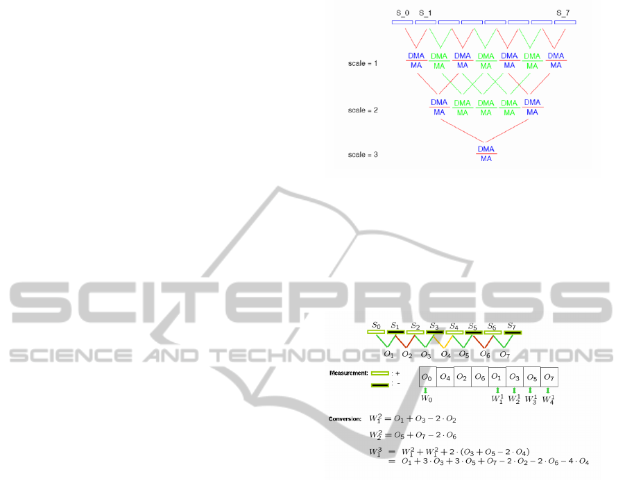
lower resolution. Fig. 1 shows an oversampled grid
for an 8-point signal, in which the highest available
resolution is used. In the figure, MA denotes the
the moving average filtering operation and DMA de-
notes the convolution of the derivative operator and
the moving average filter. The oversampling scheme
provides a representation with shift invariant coeffi-
cients and incremental update on new samples. It also
provides a possibility to extend the Haar representa-
tion over higher order (Struzik, 2001).
Inspired by this oversampling scheme, we develop
a new measurement scheme. It eliminates the redun-
dancy in the oversampled representation, while still
records all the information needed for restoring the
Haar wavelet coefficients as well as the oversampled
representation. Fig. 2 shows the measurement scheme
Figure 1: Oversampled scheme of Haar wavelet transform.
with a 1D sensor array. This measurement scheme is
suitable for hardware implementation and records the
difference of adjacent input signals. Obviously, the
Haar wavelet coefficients can be obtained by a simple
recursive calculation. In this sense, this measurement
is equivalent to the Haar wavelet coefficients.
Figure 2: Measurement scheme with 1D sensor array.
3 WAVELET MEASUREMENT IN
2D SPACE
The standard 2D Haar wavelet decomposition is ob-
tained by computing a 1D Haar transform on each
row, followed by a 1D Haar transform on each column
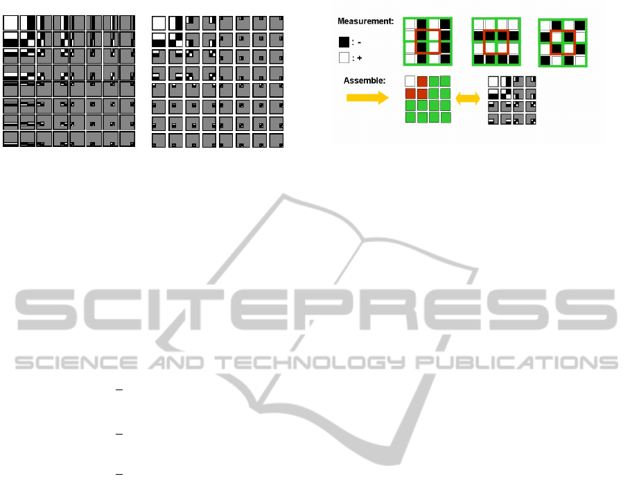
(or conversely). Fig. 3(a) shows the basis functions
of the standard 2D Haar wavelet transform. Pixel
values are added where the white color appears and
subtracted where the black color appears. From the
figure, we conclude that the standard Haar transform
generates different spectral coefficients on different
decomposition levels. A naive extension of the pre-
vious 1D measurement is not working in 2D case. We
have to turn to some alternative wavelet decomposi-
tion method.
3.1 Dyadic Wavelet Transform
It is well known that the dyadic wavelet transform is
a more efficient representation for the entropy cod-
IMAGAPP 2011 - International Conference on Imaging Theory and Applications
28
(a) (b)
Figure 3: Haar wavelet transform in 2D space (a): Basis
functions of the standard Haar wavelet transform; (b): Basis
functions of the dyadic Haar wavelet transform.
ding in image compression. It is a slightly modified
2D Haar wavelet transform, whose basis functions are
shown in Fig. 3(b). The alternation between rows
and columns are applied within each decomposition
steps, leading to a multi-scale version of three inde-
pendent basis patterns. The wavelet basis functions
can be interpreted as three independent forms in dif-
ferent scales:
Ψ
H
=
1
4
+1 −1
+1 −1
(1a)
Ψ
V
=
1
4
+1 +1
−1 −1
(1b)
Ψ
D
=
1
4
+1 −1
−1 +1
(1c)
This structure avoids the sequential operation along
rows and columns in the standard Haar wavelet trans-
form, providing a possibility to implement a parallel
measurement.
3.2 2D Oversampling-based
Measurement
Inheriting the spirit of the oversampling scheme, we
propose a novel measurement scheme in 2D space.
It contains three different basis patterns. Those pat-
terns are independent of each other, which leads
to a parallel architecture in hardware implementa-
tion. As we know, the oversampling scheme has
severe redundancy. In this measurement, only the
dyadic wavelet coefficient related measurements are
reserved. The selection principle is a matter of art,
which induces a delicate symmetric template. Com-
bining the three patterns with a selection template, the
2D oversampling-based measurement is determined.
Fig. 4 shows the measurement scheme for a 4×4 sen-
sor array.
The chessboard-like patterns represent the differ-
ent manners interpreting the sample value from each
Figure 4: Measurement scheme for 2D sensor array.
sensor. White color means counting the sample value
as positive, while the black color means counting it as
a negative sample value. For 4 × 4 sensor array, the
selection pattern has two levels. The green blocks are
the first level and the red blocks are the second level.
Each block contains four pixels, whose signed sum-
mations constitute the measurements. The acquired
measurements can be reassembled in a similar form
as dyadic wavelet coefficients. Obviously, the first
level measurements are consistent with the first level
dyadic wavelet coefficients. The second level dyadic
wavelet coefficients can be derived by a linear combi-
nation of the derived measurements. The relationship
is shown in Fig. 5.
Similarly, in the 8 × 8 and 16 × 16 cases, the
dyadic wavelet coefficients in higher levels can be
computed recursively. The three different patterns re-
main the same for larger sensor arrays. They are con-
structed by repeating the basis functions defined in
Eq. 1 respectively. The selection template distribution
obeys strict rules and is highly symmetric. This ar-
chitecture benefits the hardware implementation. The
independence of three patterns provides a parallel ar-
chitecture shown in Fig. 6. Compared with the tra-
ditional dyadic wavelet transform, this measurement
has a simpler structure, which avoids complicated
switch operations in hardware design. The pattern
number and the rule for selection template construc-
tion remain unchanged when the size of sensor array
increases, which simplifies the circuit design process.
All the computation can be carried out simultane-
ously, leading to less process time. Besides, only the
difference of adjacent pixels is recorded, which cap-
tures the true features of an object and eliminates the
affect of the illumination condition. Since the vari-
ance of the difference value is generally smaller than
the variance of absolute value, the throughout can be
reduced after the quantization step.
A NOVEL WAVELET MEASUREMENT SCHEME BASED ON OVERSAMPLING
29
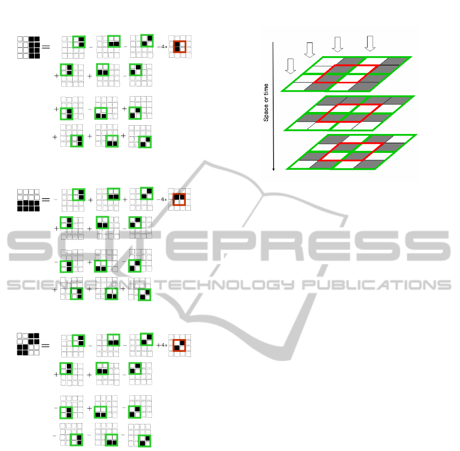
(a)
(b)
(c)
Figure 5: Second level dyadic wavelet functions.
4 SIMULATION AND
HARDWARE DESIGN
This measurement scheme is equivalent to the dyadic
Haar wavelet decomposition. In this section, we sim-
ulate the measuring process and compare the results
with the coefficients of the dyadic Haar wavelet trans-
form. The measurements can be converted to dyadic
Haar wavelet coefficients in any level, which guaran-
tees the flexibility of postprocess. Furthermore, we
propose a design guideline for a CMOS sensor de-
sign.
Figure 6: Parallel architecture.
4.1 Simulation Results
The measurement process is simulated with a given
matrix, and a test image in order to verify its accuracy.
We start with a given 4 × 4 matrix:
A =
64 2 3 61
9 55 54 12
17 47 49 20
40 26 27 37
(2)
The oversampling-based measurement is given as:
M =
32.6875 0.2500 4.0000 −4.0000
−3.2500 0.7500 −4.0000 4.7500
0.5000 −0.5000 27.0000 −25.0000
−0.5000 1.2500 −11.0000 9.7500
(3)
In order to verify the equivalent of the measure-
ments and the dyadic Haar wavelet decomposition,
we convert the measurements based on the relation-
ship given in Fig. 5. The derived matrix is the same
as the results applying the dyadic wavelet transform
directly.
W =
32.6875 −0.1875 4.0000 −4.0000
−0.1875 0.1875 −4.0000 4.7500
0.5000 −0.5000 27.0000 −25.0000
−0.5000 1.2500 −11.0000 9.7500
(4)
Fig. 7 shows a simulation example with an image
input. The value of the novel measurement scheme
is compatible to the dyadic Haar wavelet transform
with the highest level. Through recursive computa-
tions, the measurement matrix can be converted to the
dyadic Haar wavelet coefficients. The equivalence is
verified. Then an inverse dyadic Haar wavelet trans-
form is applied to the coefficients, the reconstructed
image is shown in Fig. 7(d).
IMAGAPP 2011 - International Conference on Imaging Theory and Applications
30
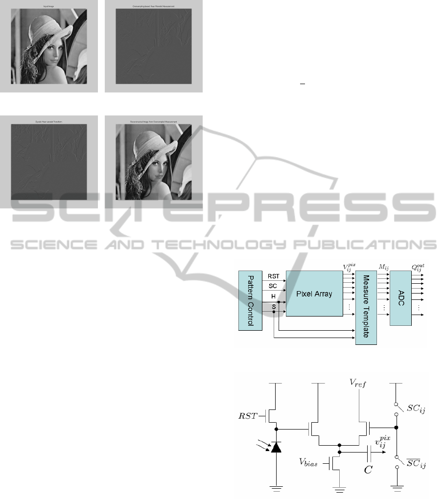
(a) (b)
(c) (d)
Figure 7: 2D measurement simulation (a): Test image;
(b): Oversampling-based measurement; (c): Converted to
dyadic wavelet coefficients; (d): Reconstructed image.
4.2 Hardware Design
This measurement scheme can be applied in dif-
ferent sensor systems together with certain postpro-
cessing blocks, such as noise removal, image cod-
ing/compression and etc. Its fixed template simplifies
the complexity of hardware implementation.
Here, we propose a schematic of hardware imple-
mentation in a CMOS sensor array in Fig. 8. It con-
tains four main parts: pattern control unit, sensor ar-
ray, measurement template and AD converter.
The pattern control unit generates the control sig-
nal with respect to three patterns, such as sample/hold
signal and sign control signal. The sign control signal
is generated by logic circuits for each basis pattern.
A modified S/H circuit is described in Fig. 9.
It is set up based on the conventional APS design
(Chi et al., 2009) with a sign control function, which
counts the accumulated photons as a positive or nega-
tive output voltage. Clocks S/H are non-overlapping.
If SC (stands for sign control) is low during the sam-
ple phase S and goes high during the hold phase H, the
amount of charge transferred is C(V
int
i j
−V
re f
), where
V
int
i j
is the voltage collected in the sample phase. V
re f
is defined as the pixel voltage when there is no light.
Conversely, if SC is high during the sample phase S
and goes low during the hold phase H, the amount of
charge transferred is C(V
re f
−V
int
i j
).
The main computation unit is the measurement
template unit. It contains basic measurement el-
ements arranged as the selection template defined
above. A basic measurement element is shown in
Fig. 10, which computes the weighted sum of adja-
cent pixel in an image. The capacitor is set to 4C in
order to get a normalized measurement. The output
of the amplifier is given as:
M
i j
=
1
4
∑
i, j
(V
int
i, j
−V
re f
) · SC
i j
. (5)
where SC
i j
is either +1 or −1. In the end, the mea-
sured differences are quantized through a AD con-
verter. This hardware design is only an example of
this measurement realization, in which the measure-
ment process is done consecutively. It contains a
switch circuits transferring one basis pattern to an-
other. The measurement scheme can also be carried
out simultaneously, which means implementing the
measurement template concerning each pattern layer-
by-layer. It avoids the switch operation between the
three patterns, hence it is faster, but the manufacture
cost for the chip is also higher. With different applica-
tions, certain circuits should be changed accordingly.
Figure 8: Hardware architecture.
Figure 9: S/H circuit with sign control.
5 CONCLUSIONS
In this paper, we propose an oversampling-based
wavelet measurement scheme. It records only the dif-
ference of adjacent pixels, capturing the true charac-
ter of an object. It eliminates the redundancy which
A NOVEL WAVELET MEASUREMENT SCHEME BASED ON OVERSAMPLING
31
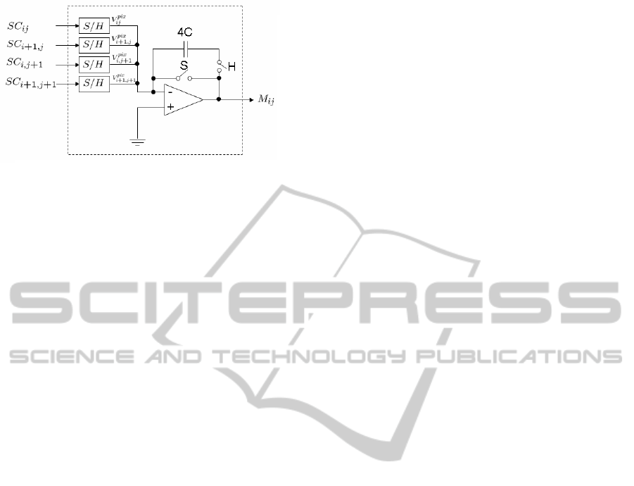
Figure 10: Basic measurement element.
occurs commonly in the oversampling system and re-
stores only the measurements equivalent to the dyadic
wavelet decomposition. The measurement scheme
can be carried out by combining three independent
chess-board like patterns with one fixed selection
template. The hardware architecture is much simpler
than the traditional wavelet transform. The indepen-
dent pattern structure provides a possibility of paral-
lel computations. Combined with certain postprocess
units, it can be used in different applications, espe-
cially the occasions requiring real-time image acqui-
sition and processing.
REFERENCES
Antonini, M., Barlaud, M., and Daubechies, I. (1992). Im-
age coding using wavelet transform. IEEE transac-
tions on image processing, pages 205–220.
Chi, Y. M., Abbas, A., Chakrabartty, S., and Cauwenberghs,
G. (2009). An active pixel CMOS separable transform
image sensor. In Proc. IEEE Int. Symp. Circuits and
Systems, Taibei, Taiwan.
Haapala, K., Kolinummi, P., Hamalainen, T., and Saarinen;,
J. (2000). Parallel DSP implementation of wavelet
transform in image compression. In The Proc. IEEE
International Symposium on Circuits and Systems,
pages 89 – 92, Geneva , Switzerland.
Haar, A. (1910). Zur theorie der orthogonalen funktionen-
systeme. Math. Annal., pages 331–371.
Lewis, A. S. and Knowles, G. (1992). Image compression
using the 2-D wavelet transform. IEEE transactions
on image processing, pages 244–250.
Luo, Q. and Harris, J. (2002). A novel integration of on-
sensor wavelet compression for a CMOS imager. Cir-
cuits and System, 3:III 325–III 328.
Mosqueron, R., Dubois, J., and Paindavoine, M. (2006).
Embedded image processing/compression for high-
speed CMOS sensor. In European Signal Processing
Conference, Florence.
Olyaei, A. and Genov, R. (2007). CMOS focal-plane
spatially-oversampling computational image sensor.
Circuits and System I, pages 26–34.
Porwik, P. and Lisowska, A. (2004). The Haar-wavelet
transform in digital image processing: its status and
achievements. Machine graphics & vision, 13:79–98.
Raviraj, P. and Sanavullah, M. Y. (2007). The modified 2D-
Haar wavelet transformation in image compression.
Middle-East Journal of Scientific Research, 2(2):73–
78.
Shoushun, C., Bermak, A., Yang, W., and Martinez, D.
(2006). A CMOS image sensor with combined
adaptive-quantization and QTD-based on-chip com-
pression processor. In Custom Integrated Circuits
Conference, pages 329–332, San Jose, CA.
Struzik, Z. R. (2001). Oversampling the Haar wavelet trans-
form. Technical report, Information Systems in CWI.
IMAGAPP 2011 - International Conference on Imaging Theory and Applications
32
