
A NOVEL SPATIAL MICROCHANNEL FLUIDIC JOINT
Benjamin Chang, Allison Chew and Carlo Menon
MENRVA group, Simon Fraser University, Burnaby, BC, Canada
Keywords: Fluidic, Polymer, Biomedical, Joint, Actuation.
Abstract: This paper presents and discusses a flexible, polymer-based, novel microchannel fluidic joint (MFJ) that is
driven by a pressurized working fluid. The MFJ has been designed for being used in biomedical
applications in the future. The MFJ actuating system has two degrees of freedom and implements a unique
3-channel design. In this paper, a prototype of the proposed MFJ is presented along with its manufacturing
procedure. Measurements related to the MFJ displacements are presented and a simplified fitting
exponential equation is proposed to describe the relationship between MFJ deformation and the working
fluid pressure. Performance of the proposed device and its potential future applications are discussed.
1 INTRODUCTION
Fluidic actuators are relatively simple systems that
can be beneficial for a diverse range of devices.
Whereas many actuators require an electric voltage,
a magnetic field, or temperature changes to operate,
fluidic actuators require only a hydraulic pressure to
bend and/or deform.
The earliest design of a fluidic actuator consists
of a soft, cylindrical rubber tube containing three
chambers that extend parallel to the tube’s axis.
When a hydraulic pressure is forced through any of
the three chambers, the actuator is able to bend in
three primary directions (Suzumori, et al., 1991).
This design offers a multi-dimensional movement, a
property that is not found in all fluidic actuators.
However, it requires a number of different
components and its long chambers do not allow for
an even distribution of force throughout the actuator.
An example of a simple, easy-to-manufacture
actuator consists of a pneumatically controlled
balloon attached to a flexible material; when the
balloon expands, the actuator bends in on direction
(Kawai, et al., 2001). The trade-off is simplicity of
design for a limited range of motion. A final
example of a fluidic actuator is a hydraulic suction
actuator. This design consists of a metal-reinforced
silicon-rubber tube whose bending angle is
controlled by hydraulic suction (Muvari, et al.,
2003). The metal reinforcements are dispersed
evenly along the tube, and the actuator can produce a
large bending angle (Muvari, et al., 2003). The
complexity of the design and numerous materials
assumes a complex manufacturing process.
Additionally, the metallic components may not be
desirable in all environments, such as the human
body.
In this paper, we discuss the design of a spatial
MFJ. It is a novel fluidic-powered device that is
composed of one single polymer, is easy to
manufacture, and can move in 2 dimensions. We
first present the structure and desired function of our
design and explain the manufacturing process of a
spatial MFJ. In order to justify our design
conjecture, we perform a series of practical tests and
provide experimental verification to our design
hypotheses. Finally, we propose several applications
in which our device can be integrated.
2 PROPOSED CONCEPT
We present a MFJ that can be implemented as an
active catheter or catheter guide. With this design,
the user will be able to control the bendable catheter
while it is inside the patient. This will facilitate the
intubation process by allowing the user to navigate
the catheter around obstacles and access the
intubation destination more easily.
Active catheters are not a novel concept. One
example of an active catheter design incorporates
shape memory alloy (SMA) actuators embedded in a
mechanism made of silicon, glass, aluminium, and
an integrated circuit (Lim, et al., 1996). Other
238
Chang B., Chew A. and Menon C..
A NOVEL SPATIAL MICROCHANNEL FLUIDIC JOINT.
DOI: 10.5220/0003168102380243
In Proceedings of the International Conference on Biomedical Electronics and Devices (BIODEVICES-2011), pages 238-243
ISBN: 978-989-8425-37-9
Copyright
c
2011 SCITEPRESS (Science and Technology Publications, Lda.)
designs also consist of SMA actuators and other
metallic components (Haga & Esashi, 1998).
Although these devices ease the intubation process,
their designs are complex and require electronic
components and power. The proposed MFJ would
provide a simpler and effective alternative to
intubation processes.
3 MFJ DESIGN
The special MFJ is bendable and driven by hydraulic
(or pneumatic) pressure. The MFJ is made from a
deformable polymer embedded with a sub-
millimeter-scale channel. The channels, illustrated in
Figure
1, have rounded edges and uniform turns that
will help to evenly distribute the force throughout
the MFJ.
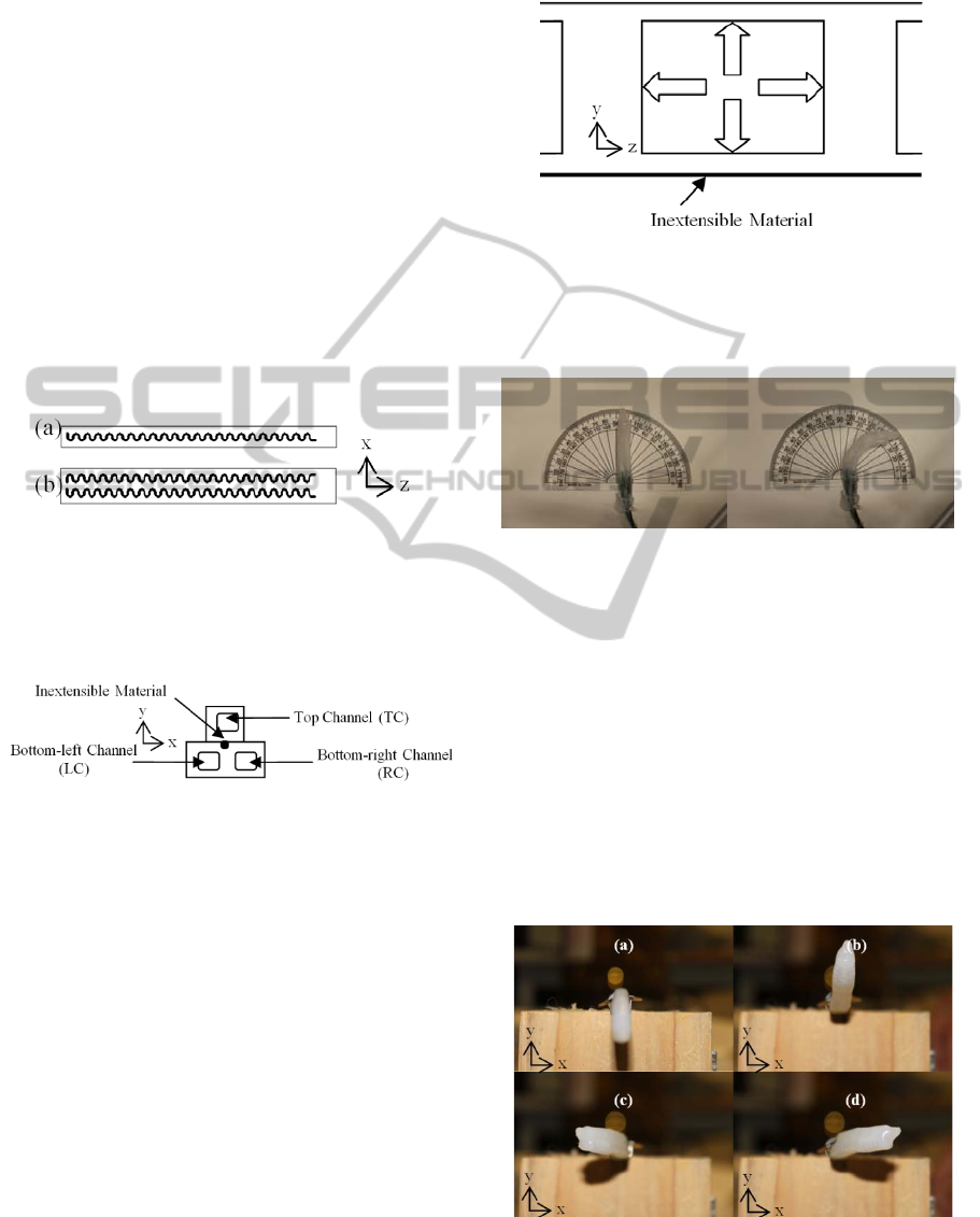
Figure 1: CAD drawing of two designs (a) Single-channel.
(b) Double-channel.
The two components shown in Figure 1(a) and (b)
are bonded together in the configuration shown in
Figure 2.
Figure 2: Arrangement of single-channel (top) and double-
channel (bottom) components.
In order for the MFJ to bend in the x-y plane, a
relatively inextensible material must be placed in the
centre of the MFJ. This material should have a much
higher Young’s Modulus than the deformable
polymer. The black circle in Figure 2 represents the
inextensible material, placed along the z-axis in
between the channels of the double-channel
component. When a hydraulic pressure is introduced
to a channel, it will exert force on all four walls of
the channel. This idea is illustrated in Figure 3,
which shows a cross-sectional view of an MFJ
channel. When a fluid exerts force in the z-axis, the
difference in elasticity between the two materials
will cause the MFJ to bend toward the inextensible
material. The force exerted in the y-axis will cause
the top and bottom walls of the channel to swell
slightly; this may cause the MFJ to break if
thehydraulic pressure is too high.
Figure 3: Force exerted on the walls of a channel.
Figure 4 shows an example of a MFJ bending up
to 40 degrees when subjected to an internal pressure
of less than 20 psi.
Figure 4: Deformation of a 40mm long MFJ, larger than
40 degrees.
The channel configuration of the spatial MFJ
enables movement in 2 dimensions. Activation of
the top channel causes the MFJ to bend downwards,
activation of the bottom-right channel causes the
MFJ to bend to the left, simultaneous activation of
the bottom-left and top channels causes the MFJ to
bend to the right, and activation of both bottom
channels causes the MFJ to bend upward. The
motions described above are illustrated in Figure 5.
Note that the MFJ can also bend diagonally in all
directions by activating different combinations of
channels.
Figure 5: Bending of a special MFJ prototype. (a)
Activation of the top channel. (b) Activation of both
A NOVEL SPATIAL MICROCHANNEL FLUIDIC JOINT
239
bottom channels. (c) Activation of the bottom-right
channel. (d). Simultaneous activation of the bottom-left
and top channels.
4 MANUFACTURING
Firstly, two different molds with specific shapes and
channel designs are required to make a spatial MFJ.
Figure 1(a) is a sketch of the single-channel mold,
consisting of a single meandering channel and an
outer rectangular frame. Figure
1(b) is a sketch of
the double-channel mold, which is twice the width
of the first and consists of 2 meandering channels
and an outer rectangular frame.
The molds are sketched on AutoCAD and are 40
millimeters (mm) long, 3 or 6mm wide, and have a
0.3mm channel width. The sketches serve as
templates that are etched onto a piece of Poly(methyl
methacrylate) (PMMA) with a CO
2
, 50-Watt, X-660
Universal laser engraver at 80% power and 15%
speed. To facilitate mass production, multiple molds
can be etched onto one piece of PMMA, as seen in
Figure 6. PMMA was chosen as a suitable material
mainly because the polymer does not adhere to it.
Therefore, after the polymer has been poured onto
the mold and cured, it can easily be removed. It was
also chosen over other materials because of its cheap
cost and its high glass transition temperature, which
prevents the material from excessive warping. The
MFJ molds shown in Figure 6 have the same
channel dimensions as stated previously. Notice how
there is a single piece of thread running between the
channels of the double-channel mold. This thread
serves as the inextensible material of the spatial
MFJ. out of TC-5005 polymer (manufactured by
BJB Enterprises, Inc.).
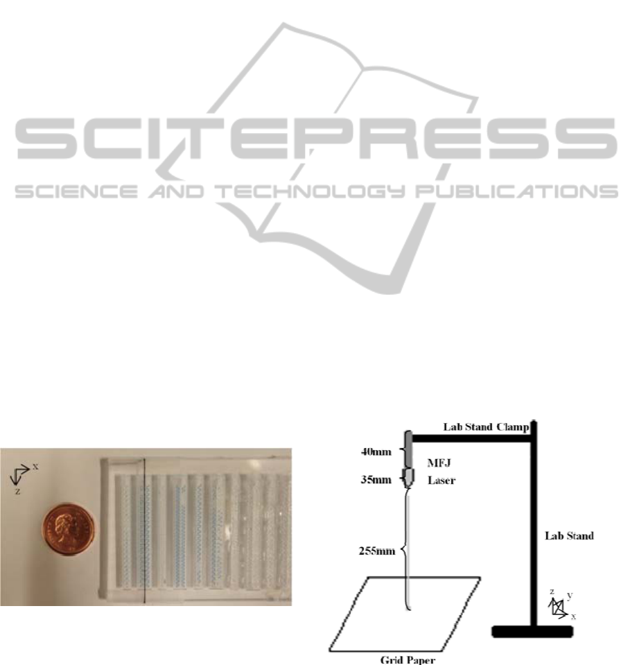
Figure 6: Spatial MFJ Molds.
The polymer is prepared by mixing 10 parts A
with 1 part B in a beaker and placing it in an
ultrasonic cleaner for 3 minutes to ensure a thorough
and even mixture. This process will cause bubbles to
form within the mixture. In order to remove these
bubbles, the polymer is poured onto a mold and
placed in a vacuum chamber for approximately 60
minutes to de-gas. It is important to place the
polymer on the mold before de-gassing it because
TC-5005 has a work-life of only 45 minutes. The
polymer is set aside to cure for at least 18 hours.
Once the polymer has cured, it is removed from
the molds, resulting in a single-channel component
and a double-channel component. The back of each
component is sealed with a thin layer of TC-5005 so
that there is no leakage when fluid is introduced to
the system. Once the components are sealed, they
are glued together in the formation shown in Figure
2.
The resulting system consists of 1 single-channel
and 1 double-channel component. 3 pieces of wire
skin are inserted into each of the 3 channels to
facilitate the injection of fluid into the channels.
Wire skin is chosen because TC-5005 adheres to this
material, creating a good seal and preventing
leakage. To finalize the design, the system is dipped
in TC-5005 polymer, resulting in a single spatial
MFJ with rounded edges.
5 MFJ TESTING
To analyze and characterize the MFJ, a test to
correlate the driving pressure and actuation
displacement is designed. The tip of a MFJ is
attached to a laser and then hung from the root with
the laser pointing down towards a grid paper. A
graphical illustration of the experimental setup is
shown in Figure 7.
Figure 7: Illustration of Experimental Setup.
BIODEVICES 2011 - International Conference on Biomedical Electronics and Devices
240
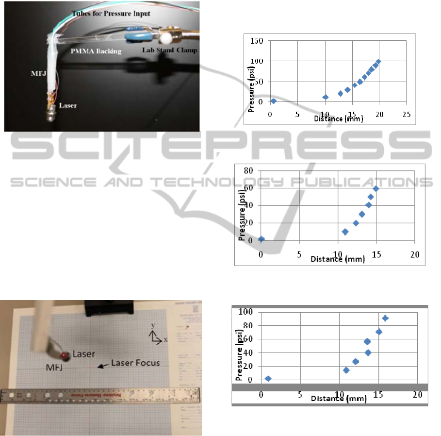
Figure 8 illustrates how a MFJ is attached to a
laser pointer at the tip and attached to a PMMA
backing at the root then secured to a lab stand. Note
that the mass of the laser head is 1.96g while the
mass of the MFJ itself is 2.26g.
Figure 8: MFJ Attached to a Laser Pointer and Secured
onto a Lab Stand Clamp.
Figure 9 illustrates how the laser is projected onto a
millimeter resolution grid paper for determining the
actuation displacement of the MFJ. The reference
and orientation of the MFJ in Figure 9 corresponds
to the reference frame shown in Figure 2. The origin
of the measurement reference frame is defined as the
point indicated by the laser projection while all
channels are not pressurized. The top channel (TC),
bottom-left channel (LC) and bottom-right channel
(RC), shown in Figure 2, were independently and
simultaneously pressured during the tests.
Figure 9: Laser Focused on a Millimeter Resolution Grid
Paper.
To measure the driving pressure to the MFJ, two
pressure gauges are used in the experiment: a WIKA
standard bourdon tube series -30 to +30 psig
pressure gauge and an Omega PX209 pressure
gauge. During the experiment, only one or two of
the channels RC, LC and TC are pressurized and
monitored with a pressure gauge. The pressure is
manually induced with Becton-Dickinson 10mL
plastic disposable syringes. At each set of pressures
tested, an x and y displacement read from the grid
paper is recorded along with the driving pressures.
Figure 10 Figure 12 illustrates the pressure VS
actuated distance while pressurizing only one
channel.
Figure 10: TC Pressure VS Distance from Origin while
RC and LC are not pressurized.
Figure 11: RC Pressure VS Distance from Origin while
TC and LC are not pressurized.
Figure 12: LC Pressure VS Distance from Origin while TC
and RC are not pressurized.
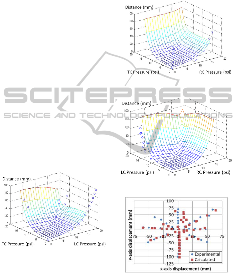
From the x and y displacement data gathered
while pressurizing individual channels and by
assuming that the three channels have independent
behaviors, exponential function curve fitting is
performed. By superimposing the effects of
pressurizing the three channels, we are able to
correlate the motion of the MFJ with the driving
pressures (using MATLAB Curve Fitting Toolbox)
as presented in the following equations:
A NOVEL SPATIAL MICROCHANNEL FLUIDIC JOINT
241
=
+
+
(1)
=
+
+
(2)
where P1, P2 and P3 are the driving pressures
respectively within TC, RC and LC in psi
respectively, and the values or the coefficients a
1
-a
6
and b
1
-b
6
are summarized in Table 1.
Table 1: Coefficients used in Equations (1) and (2).
a
1
1.171 b
1
0.0278
a
2
-1.533 b
2
0.2112
a
3
0.3247 b
3
0.3313
a
4
0.1843 b
4
0.3724
a
5
-0.1334 b
5
0.4113
a
6
0.002285 b
6
0.5300
To visualize the fitting function we have devised,
Figure 13-Figure 15 illustrate surface mesh
generated with Equation (1) and (2) plotted against
actual data points gathered while activating sets of
two channels and keeping one channel passive . The
normalized root mean square error (NRMSE) for the
surface plots are
4.3% in Figure 13, 6.7% in Figure
14, and 12.1% in Figure 15
.
The data presented in Figure 13-Figure 15 shows
that our mathematical model is able to approximate
the movement of the MFJ. However the high
NRMSE suggests that the actuations contributed by
the three channels are not completely independent of
each other.
Figure 13: TC and LC Pressure VS Displacement.
Interpolated Mesh plotted against data collected.
To further illustrate both the experimental and
modeled behavior of the MFJ, Figure 16 plots the
data points projected by the laser pointer onto the
xy-plane. The RSME for these data points are 5.7%
in the x-direction and 3.8% in the y-direction.
We are able to approximate the behavior of the
MFJ, but have also noticed that the actuations
contributed by the three channels do have some
Figure 14: TC and RC Pressure VS Displacement.
Interpolated Mesh plotted against data collected.
Figure 15: LC and RC Pressure VS Displacement.
Interpolated Mesh plotted against data collected.
Figure 16: Projection of MFJ Movement onto xy-plane.
dependency on each other. Inducing a driving
pressure into a channel will cause the stiffness and
other parameters of the system to change in a
nonsymmetrical fashion. Therefore, the linear
BIODEVICES 2011 - International Conference on Biomedical Electronics and Devices
242

independence of each channel that was assumed
during the derivation of equations 1 and 2 does not
necessarily hold true. The average NRMSE for our
experimental data is approximately 7.7% for the 3-
dimensional surfaces, and 4.7% for the 2-
dimensional plot.
6 DISCUSSION AND FUTURE
WORK
The spatial MFJ’s wide range of motion that was
proposed in the design concept is indeed supported
by experimental analysis. The projection of the
MFJ’s movement spans all 4 quadrants of the x-y
plane. Furthermore, relatively large displacements
(greater than 40 degrees as seen in Figure 4) can be
achieved by applying no more than 20psi of fluidic
pressure.
This wide range of motion, along with its
lightweight, non-metallic parts and non-electric or
magnetic stimulation make the spatial MFJ a
desirable device to insert into the human body.
Therefore, it may be useful for biomedical
applications based on its performance and
composition. Some characteristics of the MFJ are
summarized in Table 2.
Table 2: Summary of MFJ Characteristics.
Dimension
40 × 6 × 7
Mass 2.26g
Max rotation
>40 deg
Max pressure
required
21.5 psi
The pressure in the channels can be controlled
with syringes and syringe pumps, which help to
control the pressure input. Using equations 1 and 2,
the user can know approximately what pressures
must be input into each channel in order to achieve a
desired position. This system may be useful in
intubation processes such as laryngoscopy,
endoscopy, or colonoscopy, in which a destination
can be viewed with a camera, and appropriate
pressures can be input into the system so that the
MFJ can reach the desired destination.
7 CONCLUSIONS
In this paper, we presented the design of the MFJ,
which potentially provides solutions to the
shortcomings of previous fluidic and pneumatic
actuators. The MFJ displays large multi-dimensional
movements (rotations greater than 40 deg), is
lightweight (about 2g), compact in size (about 1.7
cm
3
), and has a predictable pressure-displacement
behavior. We have developed a simplified
mathematical model, which approximates the
relationship between the pressure in the three MFJ
channels and the MFJ displacements; error between
model prediction and experimental data is about
7.7%. Such an error could potentially be
dramatically reduced if the effect of each channel to
the other channels could be taken into account. It
should be noted that by scaling the fabrication mold
up or down, the dimension of the MFJ could be
easily altered for different applications. The device
presented in this paper is made of a polymer-based
material and implements a unique channel design.
The manufacturing process is very simple, contains
few components, and allows for mass production.
These properties make the spatial MFJ potentially
useful in bio-mechatronic applications.
ACKNOWLEDGEMENTS
This work was supported by the Natural Sciences
and Engineering Research Council of Canada
(NSERC). The authors would like to thank Verathon
Medical Canada.
REFERENCES
Lim, G., Park, K., Sugihara, M., Minaret, K., Esashi, M.,
1996. Future of active catheters. Sensors and
Actuators A, vol. 56, no. 1–2, pp. 113–121.
Kawai, F., Cusin, P., Konishi, K., 2001. Thin flexible end-
effecter using pneumatic balloon actuator. Sensors and
Actuators A 89, pp. 28–35.
Muyari, Y., Haga, Y., Mineta, T., Esashi, M., 2003.
Development of hydraulic suction type active catheter
using super elastic alloy tube. In: Proc. 20th Sensor
Symposium. Japan, 2003.
Suzumori, K., Iikura, S., Tanaka, H., 1991. Development
of flexible microactuator and its applications to robotic
mechanisms. In: Proc. 1991 IEEE International
Conference on Robotics and Automation. Sacramento,
California, April 1991.
Haga, Y., Esashi, M., 1998. Small diameter active catheter
using shape memory alloy coils. In: Proc. 11
th
IEEE
International Workshop on Micro Electro Mechanical
Systems (MEMS’98). Germany, 1998.
A NOVEL SPATIAL MICROCHANNEL FLUIDIC JOINT
243
