
ELECTROCUTANEOUS FEEDBACK SYSTEM TO IMPROVE
THE ESTIMATION OF PRESSURE APPLIED TO THE FOOT
Jan Walter Schroeder, Venketesh N. Dubey
Smart Technology Research Centre, School of Design, Engineering & Computing
Bournemouth University, Poole, Dorset, U.K.
Tamas Hickish
Royal Bournemouth and Poole Hospital and Bournemouth University Dorset, U.K.
Jonathan Cole
Poole Hospital NHS Foundation Trust, Poole, Dorset, U.K.
Keywords: Biomechanics, Sensory loss, Piezoresistive sensor, Artificial sensation, Electrocutaneous feedback,
Chemotherapy, Diabetes.
Abstract: Peripheral neuropathy can result from diseases such as diabetes and also chemotherapy for cancer. This
sensory loss can result in numbness and impairment of gait and balance. An electrocutaneous feedback
system might help these patients to overcome these problems. The idea of such a device is to equip a shoe
insole with force sensors that can detect pressure. The signals received by the sensor are processed and
amplified in a suitable form and are redirected to an appropriate area of skin more proximal on the limb via
an electrocutaneous feedback systems. In this work a low cost prototype is presented that represents a full
functional electrocutaneous feedback system. The prototype uses 4 piezoresistive sensors that are placed on
the insole of a shoe. The force sensors can detect the pressure that is applied to the foot. The
electrocutaneous feedback is given through electrical pulses. The pulse amplitude and repetition frequency
is fixed while the pulse length is controlled with the amplified signal for sensory feedback.
1 INTRODUCTION
Peripheral neuropathy can result from different
disease such as diabetes, infections or after
chemotherapy. Patients who suffer from this
condition have limitations in their daily life due to
the lack of sensory feedback from their extremities.
The loss can result in impairment in gait and
balance. It is difficult for these patients to feel the
force that they have to apply to a certain object, e.g.
the gas pedal of a car. An electronic insole with a
user friendly interface may help those patients to
improve their daily life conditions. The idea of such
a device is to equip a shoe insole with force sensors
that can detect pressure. The signals received by the
sensor are processed and amplified in a suitable
form and are redirected to an appropriate area of
skin more proximal up the limb via tactile
stimulation. These tactile stimulators can be an
arrange of types including vibration (Jeonghun,
2003), reinervation (Kuiken , 2007), air pressure
(Asumara, 2002) or electrical stimulation (Matjevic,
2008). In this study the latter is studied in more
detailed because of its effectiveness and low costs.
An economic prototype for artificial sensing with
low-cost components is presented.
1.1 Sensation of Pressure
To feel the sensation of pressure when it is applied
to the dermis, the second layer of the skin, has
sensory nerve endings located very close to the first
layer to the epidermis. Skin can be seen as a
viscoelastic media that deforms when touching
something (Maheshwari, 2008). This deformation
affects the neuron nerve endings, as an active sensor
386
Schroeder J., N. Dubey V., Hickish T. and Cole J..
ELECTROCUTANEOUS FEEDBACK SYSTEM TO IMPROVE THE ESTIMATION OF PRESSURE APPLIED TO THE FOOT.
DOI: 10.5220/0003167503860390
In Proceedings of the International Conference on Biomedical Electronics and Devices (BIODEVICES-2011), pages 386-390
ISBN: 978-989-8425-37-9
Copyright
c
2011 SCITEPRESS (Science and Technology Publications, Lda.)

for touch, under the epidermis. Neurons transmit
sensing signals as well as muscle stimulating signals
by using chemical ions to produce an electrical
charge that moves along the neuron, the action
potential. The information arrives as a sensing signal
to the brain where it is processed.
Several diseases can cause damage to the nerves
which is called peripheral neuropathy. Some of these
diseases are listed below:
- Leprosy
- Diabetes mellitus
- Idiopathic polyneuropathy
- Toxic (Alcohol, other toxics)
- Infection illness (Typhus, HIV)
- Cancer patients (Chemotherapy)
Different patterns of peripheral neuropathy affect
different parts of the body while the most common
one is peripheral polyneuropathy, which mainly
affects the feet and legs. Symptoms of peripheral
neuropathy encompass loss of sensing and other
feedback sensations.
1.2 Force Sensor Technologies
A force sensing device is mainly composed of two
elements. The force-sensitive element produces a
signal according to a physical stress while the data-
acquisition element receives the signal and collects
the data for further analysis. Besides micro-electro-
mechanical based systems, there are several sensors
that work at a molecular level and convert
mechanical stress into an electrical signal. The
deformation of a piezoelectric material leads to the
generation of a voltage potential and flow of current
that can be measured. The voltage is proportional to
the force applied to the sensor. (Maheshwari, 2008),
(Cotton, 2009), (Arshak, 2005).
Piezoresistive sensors are made up of metals and
semiconductors and change their resistance on
deformation. (Hollinger, 2006) Piezoresistive
sensors were found suitable for different biomedical
applications. A high sensitivity to deformation is
important for force sensors that are used in
biomedical applications. The piezoresistive sensors
show this behaviour (Herrera-May, 2009).
1.3 Electrical Stimulation
Electrical Stimulation is widely used in medical
diagnostics and treatment. (Zhang, 2007), (Sheffler,
2007). A pair of electrodes is applied to the skin and
current flows from one electrode to another. The
current can be alternating current (AC) or direct
current (DC) and is defined by its three criteria:
Current, frequency and pulse length
Stimulus current is usually in the range of 10 mA to
100 mA for clinical treatments, while the stimulus
voltage is usually in the range of 10 V to 100 V or
more (Robertson, 2006).
At a suitable frequency of variation (intensity or
direction) a nerve impulse or muscle contraction
occurs. For this purpose up to 100 Hz are used. But
also higher frequencies are used in the range of 1
kHz to 10 kHz. At frequencies higher than this nerve
and muscle fibres cannot respond.
The nerves which are close to the electrodes are
more affected to the stimulation. As a consequence
if low current density stimulation is applied to the
skin, the nerve fibres which normally respond to
touch and pressure, are the first to be stimulated.
With higher current density nerves which are located
more deeply, like the muscle fibres, can be
stimulated.
The shape of the signal also plays a role in the
stimulation of the nerves.
For most application a rectangular stimulus is
optimal, because the nerve fibre can accommodate
to the current of non rectangular signals. As a result
the generation of an action potential is not likely,
because the threshold for a trigger event is not
reached.
Transcutaneous Electrical Nerve Stimulation
(TENS) is often used to describe wearable devices
with pulsed current in the range of 1 to 120 Hz and a
pulse duration of about 50-200 micro sec.
1.4 Electrocutaneous Feedback
Systems
Lundborg et al. use piezoresistive sensors applied to
the fingertips to transfer sensations to the upper arm
by the use of skin electrodes (Lundborg, 1998).
Experiments in a set-up of five test subjects showed
that different pressure levels can be discriminated
with the help of the electrical impulses that were
transferred to the upper arm. In their following
research work they tested audio signals as a force
sensor feedback. The differentiation of fingers and
applied forces showed satisfying results.
Matjacic et al. (2000) developed a two-
dimensional electrocutaneous feedback system for
use in paraplegic standing. Their results indicated
that feedback signals could be interpreted after a
certain learning period.
2 MATERIALS AND METHODS
Based on the literature search and comparison of
ELECTROCUTANEOUS FEEDBACK SYSTEM TO IMPROVE THE ESTIMATION OF PRESSURE APPLIED TO
THE FOOT
387
different available technologies for tactile sensing,
the piezoresistive technique was identified as the
most suitable for the purpose of integration into an
artificial sensing device that is adjusted to patients
needs concerning weight and usability.
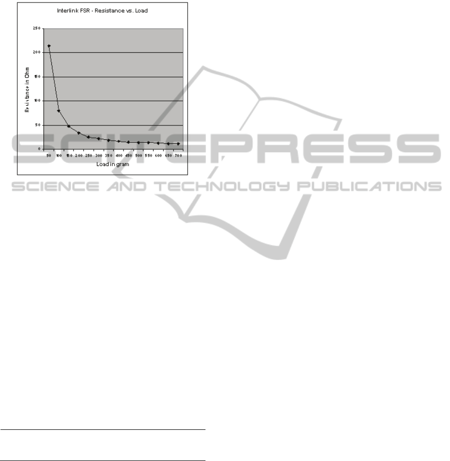
Figure 1: Resistance vs. Load for Interlink FSR.
2.1 Sensor Calibration
Figure 1 shows the calibration measurements that
demonstrate the behaviour of resistance of a
piezoresistive sensor against load which is
proportional to the force applied to the sensor.
The conductivity σ of the sensor is linear
because it is direct proportional to the reciprocal of
the resistance R and therefore suitable for the
purpose of transferring a feedback of the force as an
electrical stimulation to sensing skin, because the
conductivity can be amplified linearly.
Another calibration test was the comparison of
different sensors to define their deviation to each
other when load is applied. The arithmetic mean μ
and average deviation δ were calculated.
Table 1: Deviation test for 7 force sensor devices.
Load in g
μ of R in
kΩ Max. δ
Max. δ in
%
50 26.89 0.14285 5.18
300 259.07
-
17.06767 -6.59
Table 1 shows that the deviation for different
sensors and two loads of 50 grams and 300 grams
was at 6.59% maximum which was found to be
suitable for test purposes. However, the information
received by the sensor producer was that different
piezoresistive sensors can have a deviation up to
50%. Therefore it might be necessary to calibrate
every single sensor before it can be implemented in
an electronic insole.
2.2 Components
For the construction of the sensing system four
commercial force sensors of the type LuSense PS3
are used (Figure 2-B).
The current source is a standard 9 Volt battery.
The main components in the circuit design are an
operational amplifier and a pulse width modulator
(NE555), (Figure 2-A).
The transformer that was used is a Miniature
Audio Transformer LT700.
The link between the transformers and the skins
are electrodes of the type Ambu Neuroline 700.
3 RESULTS
3.1 Prototype Design
A first prototype giving electrocutaneous feedback
was designed. Figure 3 shows the schematics of the
design. The Sensor Unit of the prototype consists of
4 piezoresistive force sensors. The force sensors
detect pressure that is applied to the foot. An
operational amplifier helps to amplify the sensor
response. Since the conductivity of the output is
linear the voltage received by the operational
amplifier is directly proportional to the pressure
applied to the sensors.
The Pulse Creation Unit creates a pulse with a
fixed frequency and amplitude. The pulse in the
Pulse Creation Unit has a frequency of 50 Hz. The
maximum amplitude of the pulses is about 100 V.
The Pulse Creation Unit uses the output of the
Sensor Unit to modulate the pulse width of the pulse
proportional to the output with a pulse width
modulator. The pulse lies within a range of 50-200
μs and is dependent on the amplified signal of the
Sensor Unit. The pulse controls a transformer which
is part of the Electrical Stimulation Unit. The
transformers amplify the pulse from the Pulse
Creation Unit and transfer the pulse through
electrodes to the skin. The loop that is connected to
the skin is galvanically isolated from the controlling
circuit.
3.2 Preliminary Tests
A preliminary test showed that the feedback system
gives electrocutaneous feedback in the areas where
the electrodes are attached. The stronger the
BIODEVICES 2011 - International Conference on Biomedical Electronics and Devices
388
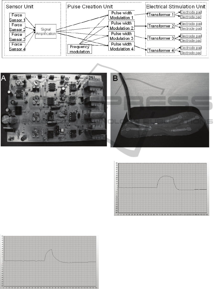
Figure 2: Circuit board (A) and Sensor Unit (B).
Figure 3: Schematic of the prototype.
electrodes are pressed the stronger the
electrocutaneous feedback is. In a first test it was
possible to differentiate which sensor was pressed.
Figure 4 shows the pulse that is applied through the
electrodes for a minimum load of 50 g. Figure 5
shows the pulse that is applied through the
electrodes for a maximum load of 1 kg. The shape
shows the behaviour of the skin that is acting like a
capacitor that is charged and discharged.
The maximum Voltage is 90 Volt represented
on the y-axis. The length of the pulse represented in
the x-axis is 100 μs at minimum load and 140 μs at
maximum load and the frequency is 28 Hz.
Figure 4: Shape of pulse on the electrodes measured with
minimum load.
Figure 5: Shape of pulse on the electrodes measured with
maximum load.
4 CONCLUSIONS
A low cost electrocutaneous feedback system was
developed and a prototype was presented. The
components of the prototype are standard materials
with low costs. In a preliminary test the feedback
system showed encouraging results. The feedback is
linear to the applied pressure on the foot, since the
pulse width changes proportional to the applied
applications. The presented design has the potential
ELECTROCUTANEOUS FEEDBACK SYSTEM TO IMPROVE THE ESTIMATION OF PRESSURE APPLIED TO
THE FOOT
389

to be applied to real patients and help them to
improve their daily life.
However certain improvements can be made to
make the device more suitable for clinical purposes.
The pulse form could be changed to an alternating
form, since a non alternating pulse can cause toxic
reaction under the electrodes because of
accumulating ions under one of the electrodes.
However for testing purposes direct current can be
used since the time of current flowing is not very
long.
The acceptance of the skin to electrical
stimulation is also nonlinear. If a microprocessor is
integrated into the design an intelligent processing of
the sensor data is possible. This would improve the
feedback. The research group presenting this paper
is currently working in processing the data from the
Sensor Unit in an intelligent way using knowledge
based systems.
The next step in our research will be the
development of a more flexible system that is taking
into account the points mentioned above. It is hoped
that patients suffering from sensory loss can have an
enormous improvement in their daily life when
using an electrocutaneous feedback system, so they
can better walk, balance and perform tasks that
require the estimation of pressure applied to the foot.
ACKNOWLEDGEMENTS
The authors want to thank Angel Torres Perez and
Adam Wright for their help in the design and the
manufacturing of the circuit board, as well as Poole
Hospital to provide the facilities for the testing.
REFERENCES
Matjevic Z., Jensen P. L., 2008. Development and
evaluation of a two-dimensional electrocutaneous
cognitive feedback system for use in paraplegic
standing, Journal of Medical Engineering &
Technology, vol. 24, no. 5. pp. 215-226
Jeonghun K., Mraz R., Baker N., A Data Glove with
Tactile Feedback for fMRI of Virtual Reality
Experiments, CyberPsychology & Behavior, vol. 6,
no. 5, pp. 497, 2003.
Asamura, N.; Yokoyama, N.; Shinoda, H., 2002,
Selectively stimulating skin receptors for tactile
display, Computer Graphics and Applications, IEEE,
vol. 18, no. 6, pp. 32-37
Kuiken T. A., P. D. Marasco, B. A. Lock et al,. 2007.
Redirection of cutaneous sensation from the hand to
the chest skin of human amputees with targeted
reinnervation," 50, PNAS, pp. 20061-20066.
Maheshwari V., and R. F. Saraf, 2008. Tactile Sensing To
Sense on a Par with Human Finger. Angew. Chem.
Int. Ed., pp. 7808-7826.
Cotton J., I. M. Graz, and S. P. Lacour. 2009. A
Multifunctional Capacitive Sensor for Stretchable
Electronic Skins. Ieee Sensors Journal, vol. 9, no. 12,
pp. 2008-2009..
Arshak K., E. Jafer, and A. Fox, 2005. Design of a new
thick film capacitive pressure and circuitry interface.
Composites Science and Technology, vol. 65, no. 5,
pp. 757-764.
Hollinger A., Wanderley M., 2006, Evaluation of
Commercial Force-Sensing Resistors, Nime06
Herrera-May, A. L. 2009, Electromechanical analysis of a
piezoresistive pressure microsensor for low-pressure
biomedical applications, Revista Mexicana De Fisica,
vol. 55, no. 1, p. 14-24
Zhang D., Guan T.H., 2007. Functional Electrical
Stimulation in Rehabilitation Engineering: A Survey.
Proceedings of the International Convention on
Rehabilitation Engineering & Assistive Technology.
pp. 221-226.
Sheffler L. R., and J. Chae. 2007. Neuromuscular
electrical stimulation in neurorehabilitation. Muscle &
Nerve, vol. 35, no. 5, pp. 562-590. Robertson, PhD,
Alex Ward, PhD, John Low, BA(Hons),
Electrotherapy Explained, 4th Edition - Principles and
Practice, BUTTERWORTH HEINEMANN , MAY-
2006
Lundborg G., B. Rosen, K. Lindstrom, 1998. Artificial
sensibility based on the use of piezoresistive sensors -
Preliminary observations. Journal of Hand Surgery-
British and European Volume, vol. 23B, no. 5, pp.
620-626
BIODEVICES 2011 - International Conference on Biomedical Electronics and Devices
390
