
DEVELOPMENT OF WEARABLE GAIT EVALUATION SYSTEM
A Preliminary Test of Measurement of Joint Angles and Stride Length
Takashi Watanabe, Hiroki Saito, Eri Koike and Kazuki Nitta
Dept. Biomedical Enginerring, Tohoku University, 6-6-11 Aramaki-aza-Aoba, Sendai, Japan
Keywords: Gait, Gyroscope, Accelerometer, Joint angle, Kalman filter, Stride length.
Abstract: The purpose of this study is to develop wearable sensor system for gait evaluation using gyroscopes and
accelerometers for application to rehabilitation, healthcare and so on. In this paper, simultaneous
measurement of joint angles of the lower limbs and stride length was tested with a prototype of wearable
sensor system. The system measured the joint angles using the Kalman filter. Signals from the sensor
attached on the foot were used in the stride length estimation detecting foot movement automatically. Joint
angles of the lower limbs and the stride length were measured with reasonable accuracy compared to those
values measured with optical motion measurement system with healthy subjects. Joint angle patterns
measured in 10m walking with a healthy subject were similar to common patterns. High correlation between
joint angles at some characteristic points and walking speed were also found adequately from measured data.
The system was suggested to be able to detect characteristics of gait.
1 INTRODUCTION
A motion measurement system has been expected to
come into widespread use for evaluation of motor
function in rehabilitation training. Although optical
motion measurement system is commonly used in
research work, the system has shortcomings that
measurement condition is limited, costs of the
system is very high and so on.
In recent years, inertial sensors such as
accelerometers and gyroscopes have been used in
measurement and analysis of human movements
because of its shrinking in size, low cost and
easiness for settings, which are suitable for clinical
application. Many studies using inertial sensors have
been performed independently in detecting gait
phase (Lau and Tong, 2008; Jasiewicz et al., 2006;
Selles et al., 2005), measurement of joint angle or
segment tilt angle (Tong and Granat, 1999;
Dejnabadi et al., 2005; Cikajlo et al., 2008; Findlow
et al., 2008), and estimating stride length (Alvarez et
al., 2007; Bamberg et al., 2008).
This study aimed to realize simplified wearable
gait analysis system using inertial sensors for
rehabilitation of motor function, daily exercise for
healthcare, and so on. For this purpose, we focused
on measurement of lower limb joint angles and
stride length simultaneously during gait.
A significant problem on measurement of joint
angles with gyroscopes is error accumulation in its
integral value caused by offset drift. In order to
reduce the offset drift problem of gyroscope, several
methods have been proposed: automatic resetting
and high-pass filtering (Tong and Granat, 1999),
applying Kalman filter to correct shank inclination
(Cikajlo et al., 2008), and applying neural network
(Findlow et al., 2008). In this study, considering
practical use, Kalman filter based joint angle
estimation of lower limbs without calibration and
resetting during measurement were proposed and
tested (Saito et al., 2009).
Stride length is usually estimated from forward
acceleration of the foot (Alvarez et al., 2007;
Bamberg et al., 2008). In the method, gait events
such as heel-off and foot-flat have to be detected to
determine integration period for calculating forward
movement velocity and forward displacement of the
foot. Foot switches or force sensitive registers are
sometimes used with inertial sensors for more
precise estimation. Other methods of stride length
estimation use mathematical model with joint angle
of lower limbs or acceleration of a different part of
the body (González et al., 2007; Lee et al., 2005). In
this study, the forward acceleration of the foot is
used to estimate the stride length. A preliminary test
showed the feasibility of estimating the stride length
245
Watanabe T., Saito H., Koike E. and Nitta K..
DEVELOPMENT OF WEARABLE GAIT EVALUATION SYSTEM - A Preliminary Test of Measurement of Joint Angles and Stride Length.
DOI: 10.5220/0003163002450250
In Proceedings of the International Conference on Bio-inspired Systems and Signal Processing (BIOSIGNALS-2011), pages 245-250
ISBN: 978-989-8425-35-5
Copyright
c
2011 SCITEPRESS (Science and Technology Publications, Lda.)

gyroscope
accelerometer
Kalman filter
θ
a
θ
−
+
−
+
y
Δ
θ
ˆ
Δ
θ
ˆ
Sensor Unit 1
L.P.F.
∫
arctan
PC
gyroscope
accelerometer
Sensor Unit 2
L.P.F. arctan
+
−
0.5Hz
+
−
Figure 1: Block diagram of angle measurement system with Kalman filter.
at each step, in which the integration period was
determined by detecting stationary state of the foot
using the accelerometer (Watanabe et al., 2009).
In order to realize practical gait analysis system,
we developed a prototype of joint angle
measurement system of the lower limbs (Saito and
Watanabe, 2010). In this paper, simultaneous
measurement of joint angles and stride length were
tested first with the developed system comparing to
optical motion measurement system with healthy
subjects. Then, the gait parameter measurement was
tested in 10m walking with a healthy subject.
2 OUTLINE OF GAIT
MEASUREMENT SYSTEM
2.1 Joint Angle Estimation
A joint angle is calculated as integral of difference
between angular velocities measured from two
gyroscopes, in which the gyroscopes are attached on
the adjacent segments. Figure 1 shows the block
diagram of joint angle measurement system using
Kalman filter.
θ
and
a
θ
are joint angles measured
with gyroscopes and accelerometers, respectively.
Initial joint angle in the integration of angular
velocity was determined by the accelerometer.
a
θ
is
calculated from difference of inclination angles of
gravitational acceleration of the segments. Outputs
of accelerometers were filtered with Butterworth
low-pass filter with cut off frequency of 0.5Hz. In
the developed system, Kalman filter estimates error
of the joint angle measured by gyroscopes
θ
ˆ
Δ
from
difference between angles obtained by gyroscopes
and those by accelerometers
yΔ
. Then, estimated
value of joint angle
θ
ˆ
is calculated.
The state of the system is represented as the error
of the joint angle measured with gyroscopes
θ
Δ
and
increment of bias offset for one sampling period
b
Δ
.
That is, the state equation is shown by:
⎥
⎦
⎤
⎢
⎣
⎡
+
⎥
⎦
⎤
⎢
⎣
⎡
Δ
Δ
⎥
⎦
⎤
⎢
⎣
⎡
=
⎥
⎦
⎤
⎢
⎣
⎡
Δ
Δ
+
+
w
w
bb
k
k
k
k
θθ
10
11
1
1
(1)
where
w
is error in measurement with gyroscopes.
Observation equation is given by:
[]
v
b
y
k
k
k
+
⎥
⎦
⎤
⎢
⎣
⎡
Δ
Δ
=Δ
θ
01
(2)
where
v
is error in measurement with
accelerometers. Kalman filter repeats corrections (eq.
(3)) and predictions (eq. (4)) as follows:
)
ˆ
(
ˆ
ˆ
ˆ
ˆ
2
1
−
−
−
Δ−Δ
⎥
⎦
⎤
⎢
⎣
⎡
+
⎥
⎥
⎦
⎤
⎢
⎢
⎣
⎡
Δ
Δ
=
⎥
⎥
⎦
⎤
⎢
⎢
⎣
⎡
Δ
Δ
kk
k
k
k
k
y
K
K
bb
θ
θθ
(3)
⎥
⎥
⎦
⎤
⎢
⎢
⎣
⎡
Δ
Δ
⎥
⎦
⎤
⎢
⎣
⎡
=
⎥
⎥
⎦
⎤
⎢
⎢
⎣
⎡
Δ
Δ
−
+
−
+
k
k
k
k
bb
ˆ
ˆ
10
11
ˆ
ˆ
1
1
θθ
(4)
where
1
K
and
2
K
are Kalman gain for
θ
Δ
and
b
Δ
,
respectively. The hat upon a character and the
superscript minus represent estimated value and
predicted value, respectively. For initial state,
−
Δ
0
ˆ
θ
was set at zero and
−
Δ
0
ˆ
b
was set at the value at the
last measurement.
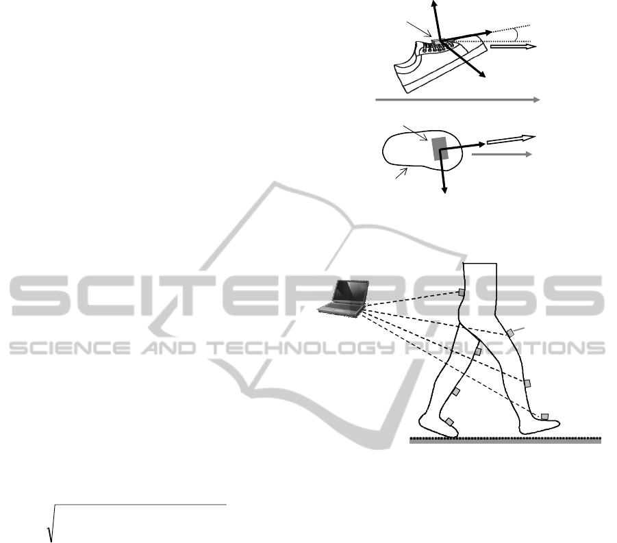
2.2 Stride Length Estimation
The stride length is estimated for each step by the
sensor attached on the foot (Figure 2(a)). Tilt angle
of the foot in the sagittal plane,
)(t
θ
, is calculated
from gyroscope output:
init
t
dt
θττθθ
+=
∫
0
)()(
(5)
Here, initial tilt angle
init
θ
is determined by average
value of 6 samples of the tilt angle obtained by the
accelerometer:
∑
=
⎟
⎠
⎞
⎜
⎝
⎛
=
5
0
)(
arcsin
6
1
n
x
init
g
na
θ
(6)
BIOSIGNALS 2011 - International Conference on Bio-inspired Systems and Signal Processing
246
The horizontal velocity is calculated under the
condition that the x and z axes are in the sagittal
plane:
()
init
t
zxh
vdaatv +−=
∫
0
sincos)(
τθθ
(7)
Initial value,
init
v
, was set at zero because the
integral of sensor signal is calculated during foot
movement excluding the stationary state of the foot
at the stance phase. In this paper, the stationary state
was detected by the accelerometer. That is, the
beginning of the step is when the sum of absolute
value of acceleration signals of 3-axes is larger than
0.15G for 3 successive samples. The end of the step
is detected when the sum of absolute value of
acceleration signals of 3-axes is smaller than 0.15G
at 3 samples in 10 successive samples. In addition,
the gait phase such as heel off, toe off, heel contact
and toe contact were also checked automatically
during the detection (Minegishi et al., 2010). Then,
the calculated velocities of the foot were corrected
so as to be 0m/s at the end of the integral by using
linear approximation. The movement velocities were
assumed to be 0m/s at the beginning and at the end
of calculation.
In the above calculation, the sensors should be
attached in exact direction of forward movement.
For actual use, misalignment of the sensor axis to
the traveling direction as shown in Figure 2 (b) was
corrected in calculating stride length L using
acceleration signal of the y-axis:
2
0
2
0
)()(
⎟
⎠
⎞
⎜
⎝
⎛
+
⎟
⎠
⎞
⎜
⎝
⎛
=
∫∫
T
y
T
h
dvdvL
ττττ
(8)
2.3 Measurement System
The wearable sensor system consists of seven
wireless sensors (WAA-006, Wireless Technologies)
and a portable PC (Figure 3). The wireless sensor
includes a 3-axis accelerometer, a 2-axis gyroscope
and a 1-axsis gyroscope. The sensors are attached on
the feet, the shanks and the thighs of both legs, and
lumbar region. Acceleration and angular velocity
signals of each sensor are measured with a sampling
frequency of 100Hz, and are transmitted to PC via
Bluetooth network. On the PC, ankle, knee and hip
joint angles of both legs are calculated and displayed
online. The measured data and calculated angles can
be saved on the PC on request. Measurement,
recording and joint angle calculation were
implemented in Labview (National Instruments).
Stride length was calculated offline using Visual
Basic.
h
a
x
y
z
forward
θ
sensor
(a)
h
a
y
x
forward
senso
r
foot
(b)
Figure 2: Attachment of sensors on the foot and velocity in
forward direction. Side view (a) and top view (b).
sensor
wireless
communication
Figure 3: Outline of a prototype of wearable sensor system.
3 EXPERIMENTS
3.1 Evaluation of Measured
Parameters
3.1.1 Method
Measurements of hip, knee, and ankle joint angles
and stride length were examined in short distance
walking with 3 healthy subjects (male, 22-23 y.o.).
The wireless sensors were attached on the feet with
adhesive tape and on the shanks, thighs and lumbar
region with stretchable bands. The optical motion
measurement system (OPTOTRAK, Northern
Digital Inc.) was used to measure reference data for
evaluating calculated joint angles and stride length.
The markers for reference data were attached on the
left side. The sensor signals and maker positions
were measured simultaneously by personal computer
with a sampling frequency of 100Hz. The subjects
walked on short distance pathway (about 3.6m) at 3
speeds (slow, normal and fast). Five trials were
DEVELOPMENT OF WEARABLE GAIT EVALUATION SYSTEM - A Preliminary Test of Measurement of Joint
Angles and Stride Length
247
performed for each walking speed started with the
left side step. The parameters of Kalman filter were
set for each joint angle with trial and error.
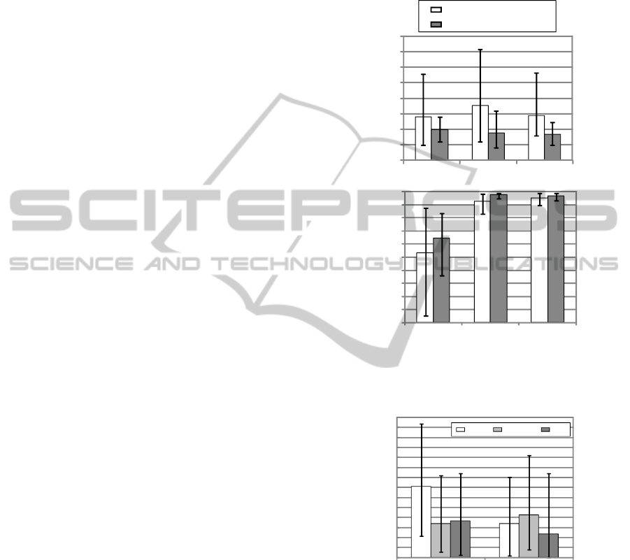
3.1.2 Results
Root mean squared error (RMSE) and correlation
coefficient (ρ) between measured joint angles and
reference values were shown in Figure 4. Values of
RMSE were decreased and ρ were increased with
the Kalman filtering method.
Figure 5 shows evaluation result of stride length
estimation. In each trial, 2 ~ 4 strides were measured
with the optical motion measurement system. In
some strides, however, the end of stride was not
detected automatically by acceleration signals.
Those trials were removed from the analysis. Errors
for the 1st stride of slow walking were larger than
other walking conditions. The errors were less than
10% in average although larger error occurred in
some cases, except for the 1st stride of slow walking.
3.2 Measurement in 10m Walking
3.2.1 Method
The developed system was tested in measurement
during 10m walking with a healthy subject (male, 23
years old). The wireless sensors were attached on
both legs in the same way as shown in the previous
section. The subject walked 10m at 3 different
speeds (slow, normal, fast). Three trials were
performed for each walking speed started with the
left side step.
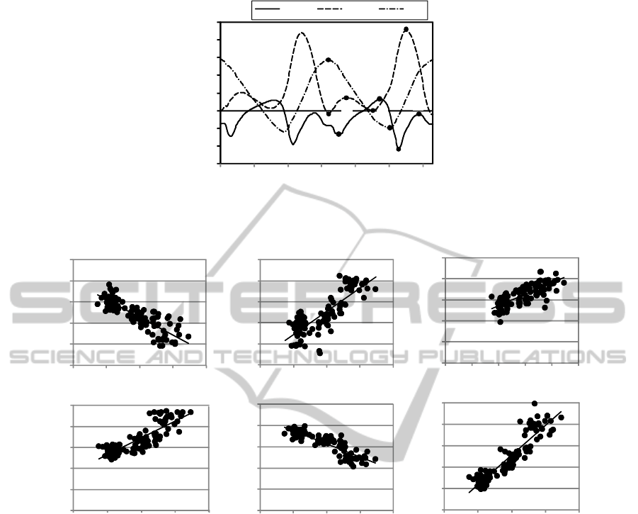
3.2.2 Results
The numbers of steps by both legs were 19, 16 and
12 steps for slow, normal and fast speeds walking,
respectively. An example of measured joint angles is
shown in Figure 6. The joint angle patterns were
similar to common patterns. All the strides were
detected automatically by acceleration signal.
In application to rehabilitation or daily exercise,
it is required to show measured data simply to
physical therapists, patients or users. In this paper,
the following ten characteristic points of the joint
angles as seen in Figure 6 were analyzed.
1) maximum ankle plantar flexion at stance
phase
2) maximum ankle dorsiflexion at stance phase
3) maximum ankle plantar flexion at swing
phase
4) maximum ankle dorsiflexion at swing phase
5) maximum knee extension around heel strike
6) knee joint angle at double knee action
7) maximum knee extension around mid stance
8) maximum knee flexion at swing phase
9) maximum hip flexion
10) maximum hip extension
ankle knee hip
ankle knee hi
p
correlation coefficient
RMSE [deg]
without Kalman filter
with Kalman filter
0
2
4
6
8
10
12
14
16
0.5
0.6
0.7
0.8
0.9
1.0
Figure 4: Evaluation results of the joint angle
measurement. Average, minimum and maximum values of
RMSE and correlation coefficient are shown.
0
4
8
12
16
20
24
28
1st stride
2nd -4th strides
absolute error [%]
slow
normal
fast
Figure 5: Evaluation results of stride length estimation.
Average, minimum and maximum values of absolute error
are shown for the 1st stride and from the 2nd strides.
The joint angles at the characteristic points were
compared with the instantaneous walking speed that
was calculated from the stride length and the time
for the stride. In this analysis, the first and the last
strides of the left leg and the last one of the right leg
were removed since they were different from steady
state gait. The joint angles which showed high
correlation with the walking speed are shown in
Figure 7. Figure 7(f) shows relationship between the
BIOSIGNALS 2011 - International Conference on Bio-inspired Systems and Signal Processing
248
-30
-20
-10
0
10
20
30
40
50
0
0.5
1
1.5 2 2.5 3
joint angle [deg]
time [sec]
ankle knee hip
1)
2)
3)
4)
5)
6)
7)
8)
9)
10)
Figure 6: An Example of joint angles for two gait cycles. The numbers on the plots indicate the characteristic points which
were analyzed in this paper.
r = 0.93
75
100
125
150
175
200
0.5 1 1.5 2 2.5
r = 0.84
0
10
20
30
40
50
0.5 1 1.5 2 2.5
r= -0.88
-50
-40
-30
-20
-10
0
0.5 1 1.5 2 2.5
r = 0.82
-10
0
10
20
30
40
0.5 1 1.5 2 2.5
r = 0.77
20
30
40
50
60
70
0 0.5 1 1.5 2 2.5
ankle max. plantar flexion
angle in swing phase [deg]
knee max. flexion angle
in swing phase [deg]
hip max. flexion angle [deg]
hip max. extension angle [deg]
knee joint angle at
double knee action [deg]
stride length [cm]
walking speed [m/s]
walking sp eed [m/s]
walking sp eed [m/s]
walking speed [m/s]
walking sp eed [m/s] walking speed [m/s]
(a)
(b)
(c)
(d)
(e)
(f)
r= -0.85
-50
-40
-30
-20
-10
0
0.5 1 1.5 2 2.5
Figure 7: Joint angles at characteristic points that have high correlation with walking speed at each stride. Relationship
between the walking speed and the stride length is also shown.
walking speed and the stride length. The result
shows high correlation between them.
4 DISCUSSIONS
Joint angles were found to be measured with stable
accuracy. Values of RMSE and correlation
coefficient were similar to those with our previous
sensors (Saito et al, 2009). However, in ankle joint
angle measurement, the Kalman filter had smaller
effect than other joints. This is considered to be
caused by movement of the sensor attached on the
foot during dorsiflexion at the stance phase.
Although the absolute errors for the 1st stride of
slow walking were large, those for other walking
conditions were less than 10% in average. In the
stride length estimation, the x and z axes were
assumed to be in the sagittal plane. The integral
interval was automatically detected using signals of
acceleration. These are considered to affect on the
estimation accuracy.
Attachment position of sensors and leg length are
considered not to significantly affect measurement
accuracy, if the sensors are aligned without rotation.
Therefore, attachment positions of the sensors were
not exactly regulated, but they were aligned roughly
in the frontal plane in the measurements. This simple
attachment of sensors is important for clinical
applications. However, movement of sensors caused
by muscle or tendon movements, misalignment of
sensors and so on have to be examined in order to
improve estimation accuracy of joint angles and
stride length with more subjects.
DEVELOPMENT OF WEARABLE GAIT EVALUATION SYSTEM - A Preliminary Test of Measurement of Joint
Angles and Stride Length
249

The measured data in 10m walking showed joint
angle patterns that were similar to the common
patterns and high correlation between joint angles at
some characteristic points and walking speed. The
correlations are seemed to be same as relationships
which are generally seen in gait of normal subjects.
The developed system is suggested to be able to
detect characteristics of gait. Other characteristic
points are also important for the use in rehabilitation.
For example, maximum ankle dorsiflexion in the
swing phase can be a practical index for evaluating
hemiplegic gait.
5 CONCLUSIONS
A prototype of wireless wearable sensor system was
evaluated in simultaneous measurement of joint
angles and stride length. The system could measure
joint angles of the lower limb and stride length with
stable accuracy on healthy subjects. The measured
gait patterns were similar to the common pattern and
high correlation between joint angles at
characteristic points and walking speed were also
found adequately with a healthy subject. The
developed system is suggested to be able to detect
characteristics of gait. Quantitative evaluation will
be performed with more subjects for improvement of
estimation accuracy. Measurement of gait with
motor disabled patients will also be in the next step.
ACKNOWLEDGEMENTS
This work was supported in part by Miyagi
Perfectural Government under the Sendai Advanced
Preventive Health Care Services Cluster, and the
Ministry of Education, Culture, Sports, Science and
Technology of Japan under a Grant-in-Aid for
Scientific Research (B).
REFERENCES
Alvarez, J. C., Gonzalez, R. C., Alvarez, D., Lopez, A. M.,
Rodriguez-Uria, J., 2007. Multisensor Approach to
Walking Distance Estimation with Foot Inertial
Sensing. Proc. 29th IEEE Eng. Med. Biol. Soc., 5719-
5722.
Bamberg, S. J., Benbasat, A. Y., Scarborough, D. M.,
Krebs, D. E., Para-diso, J. A., 2008. Gait Analysis
Using a Shoe-integrated Wireless Sensor System.
IEEE Trans. Inf. Technol. Biomed., 12, 413-423.
Cikajlo, I., Matjačić, Z., Bajd, T., 2008. Efficient FES
Triggering Applying Kalman Filter during Sensory
Supported Treadmill Walking. J. Med. Eng. Technol,.
32, 133-144.
Dejnabadi, H., Jolles, B. M., Aminian, K., 2005. A New
Approach to Accurate Measurement of Uniaxial Joint
Angles based on a Combination of Accelerometers
and Gyroscopes. IEEE Trans. Biomed. Eng., 52, 1478-
1484.
Findlow, A., Goulermas, J. Y., Nester, C., Howard, D.,
Kenney, L. P., 2008. Predicting Lower Limb Joint
Kinematics Using Wearable Motion Sensors. Gait
Posture, 28, 120-126.
González, R. C., Alvarez, D., López. A. M., Alvarez, J. C.,
2007. Modified Pendulum Model for Mean Step
Length Estimation. Proc. 29th IEEE Eng. Med. Biol.
Soc., 1371-1374.
Jasiewicz, J. M., Allum, J. H., Middleton, J. W., Barriskill,
A., Condie, P., Purcell, B., Li, R.C., 2006. Gait Event
Detection Using Linear Accelerometers or Angular
Velocity Transducers in Able-bodied and Spinal-cord
Injured Individuals. Gait Posture, 24, 502-509.
Lau, H., Tong, K., 2008. The Reliability of Using
Accelerometer and Gyroscope for Gait Event
Identification on Persons with Dropped Foot. Gait
Posture, 27, 248-257.
Lee, S. W., Mase, K., Kogure, K., 2005. Detection of
Spatio-temporal Gait Parameters by Using Wearable
Motion Sensors. Proc. 27th IEEE Eng. Med. Biol. Soc.,
6836-6839.
Minegishi. Y., Watanabe, T. Furuse, N., 2010. Gait Event
Analysis of Normal Gait by Using a Gyroscope
Attached on the Foot for Simplified Gait Evaluation. J.
Society of Biomechanisms, 34(1), 63-67 (in Japanese).
Saito, H., Watanabe, T., Arifin, A., 2009. Ankle and Knee
Joint Angle Measurements during Gait with Wearable
Sensor System for Rehabilitation. IFMBE
Proceedings: WC2009, 25/IX, 506–509.
Saito, H., Watanabe, T., 2010. Feasibility Study of
Simplified Joint Angle Measurement System Using
Wireless Inertial Sensors for Gait Evaluation. Trans.
Japanese Soc. for Medical and Biological Eng.,
48(Suppl.), in CD-ROM.
Selles, R. W., Formanoy, M. A., Bussmann, J. B.,
Janssens, P. J., Stam, H. J., 2005. Automated
Estimation of Initial and Terminal Contact Timing
Using Accelerometers; Development and Validation in
Transtibial Amputees and Controls. IEEE Trans.
Neural Syst. Rehabil. Eng., 13, 81-88.
Tong, K., Granat, M. H., 1999. A Practical Gait Analysis
System Using Gyroscopes.
Med. Eng. Phys., 21, 87-94.
Watanabe, T., Minegishi, Y., 2009. A Test of Stride
Length Measurement with an Accelerometer and a
Gyroscope Attached on the Foot. IFMBE
Proceedings: WC2009, 25/IX, 502–505.
BIOSIGNALS 2011 - International Conference on Bio-inspired Systems and Signal Processing
250
