
AUTOMATIC DEPTH ELECTRODE LOCALIZATION
IN INTRACRANIAL SPACE
Janis Hofmanis, Valerie Louis-Dorr, Olivier Caspary and Louis Maillard
Research Centre for Automatic Control, Institut National Polytechnique de Lorraine
2, av. de la fort de Haye, Vandoeuvre-les-Nancy, France
Keywords:
Electrode localization, SEEG, Coregistration, Matter segmentation, Epilepsy, CT.
Abstract:
Localization and precise targeting of depth electrodes in the regions of the human brain is critical for accurate
clinical diagnoses and treatment as well as for epileptical source localization and studies of in-vivo electrical
propagation. By using magnetic resonance imaging (MRI) combined with computed tomography (CT), the
authors present a method based on image processing and object recognition that improves electrode local-
ization in different brain anatomies and matter. This method permits the quantified localization of electrode
placements in cortex and white matter, and gives the precise position of each electrode, allowing a more de-
tailed study of intra-cranial electrical stimulation, propagation and properties of conductivity related to the
brain. Such methods can be extended to depth-scalp signal analysis using simultaneously registered SEEG
and EEG measurements.
1 INTRODUCTION
When investigating the brain processes using stereo
electroencephalography (SEEG) (Talairach et al.,
1974), the main question is how to relate given mea-
surements with spatio-temporal neural source activ-
ity. To do this, it is important to build a model that
incorporates all unknown parameters. Using recent
studies of simultaneously recorded scalp and intrac-
erebral EEG combining with deep brain stimulation
(DBS), it could be possible to relate measurements on
scalp and intracerebral activity. However, to build a
model, one must know the precise position of the elec-
trodes where DBS is executed. It is also important to
understand how the electrical conductivity is affected
by white matter, precisely, fibers of axons. To anal-
yse this in detail, we must know which depth elec-
trodes are located in white and which in gray matter.
There already exist few studies of depth electrode lo-
calization in brain anatomies. Oya (Oya et al., 2009)
presented an atlas based on SEEG electrode localiza-
tion in the amygdala. Ekstrom (Ekstrom et al., 2009)
showed how to use MRI, and 2D computational un-
folding can localize electrodes in the subregions of the
hippocampus and the parahippocampal gyrus. Both
these methods concentrate on anatomy structure seg-
mentation and not so much on electrode placements
in three dimensional brain space. Miller (Miller et al.,
2007) has constructed the Matlab package ”Location
on Cortex” to help localize subdural electrodes using
lateral X-ray images. However, this method enables
to apply subdural electrode arrays onto a standardized
template brain volume and requires neurologists to
pinpoint each electrode position manually. There are
also applications like BioImage Suite (Yale Univer-
sity, USA) (Duncan et al., 2004) that allow to edit and
place manually multicaptors or grid of electrodes ac-
cording to their position in CT scan image. This, how-
ever, is time-consuming when working with many pa-
tients and multicaptors. In this paper, the objective of
electrode localization is to develop an automatic rou-
tine that finds the origin of each electrode in 3-D CT
scan.
1.1 Acquisition Methods
Usually, the collector of electrodes, called multicap-
tor, consists of 10 or 15 separate electrodes each 2mm
wide and 0.8mm in diameter separated by 1.5mm of
isolator. For one patient, 10 multicaptors can be im-
planted, of total from 100 to 150 electrodes. Before
surgery of multicaptors, MR imaging (3D SPGR T1
weighted-sequence, TR: 20 ms, TE: 6 ms; matrix 512
X 512, with double injection of gadolinium) is applied
459
Hofmanis J., Louis-Dor V., Caspary O. and Maillard L..
AUTOMATIC DEPTH ELECTRODE LOCALIZATION IN INTRACRANIAL SPACE.
DOI: 10.5220/0003160204590462
In Proceedings of the International Conference on Bio-inspired Systems and Signal Processing (BIOSIGNALS-2011), pages 459-462
ISBN: 978-989-8425-35-5
Copyright
c
2011 SCITEPRESS (Science and Technology Publications, Lda.)
to obtain the configuration of brain anatomy for par-
ticular patients. After implementation, CT with voxel
size variating from 0.5 x 0.5 x 0.7 mm to 0.6 x 0.6 x
0.7 mm is done.
2 SEEG ELECTRODE
LOCALIZATION IN MATTER
Finding the position of intracranial electrodes and
their location with respect to brain matter can be de-
scribed in three steps: 1. Register the electrodes
in CT. 2. Co-register CT and preimplant MRI (find
transformation matrix). 3. Do matter segmentation
in MRI volume. The final step consists in calculating
the electrodes position by use of the transformation
matrix. If the boundaries are known, then we can de-
termine each electrode in matter spaces (see Figure 1).
The following sections explain these steps in detail.
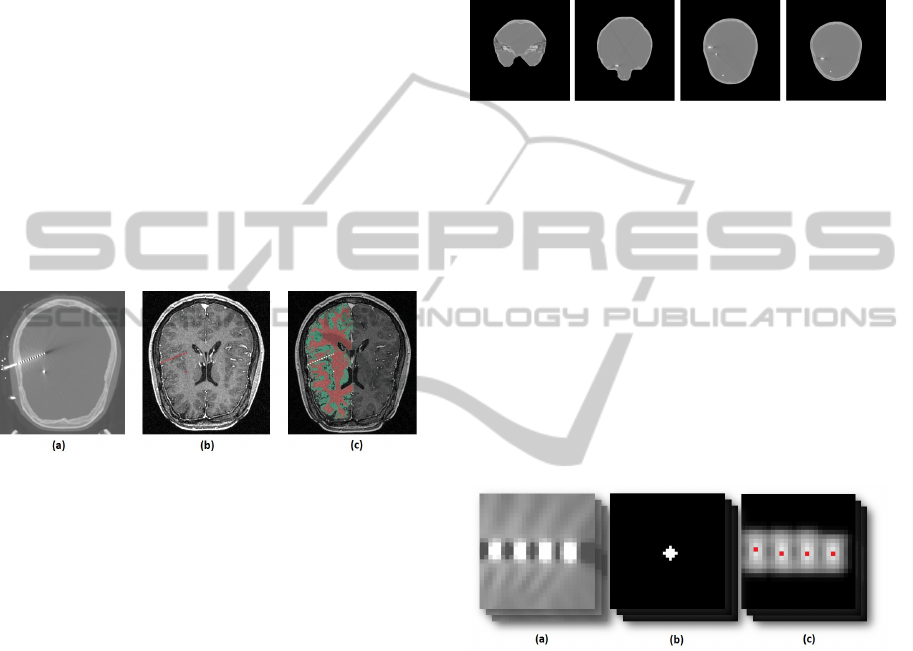
Figure 1: (a) - A slice of a CT image with electrodes, (b) -
slice of MRI with approximate position of electrodes (red),
(c) - segmented left hemisphere MRI with approximate po-
sition of electrodes (white).
2.1 Electrodes Localization in CT Scan
• skull stripping;
• correlation of the pattern;
• identification of the multicaptor;
• optimization of 3D localization.
Each of these steps is explained in detail below.
2.1.1 Skull Stripping
In order to make electrode recognition routines work
optimally, extraneous artifacts that do not contain
depth electrodes, must be removed from the images.
This includes all data outside the skull and intracra-
nial space where multicaptors are located. There are
many studies for fast skull stripping in MRI (Dale
et al., 1999; Hahn and Peitgen, 2000) and CT scan
(Maldjiana et al., 2001; Lee et al., 2008). Suggestions
for skull stripping together with implanted depth elec-
trodes was not found. Furthermore, some electrodes
can be located in the skull itself, so we need a method
for segmenting the area of intracranial space together
with the skull. To satisfy these conditions, we devel-
oped a procedure based on intensity level threshold-
ing and image morphological processing methods to
segment intracranial space. The result of four seg-
mented slices is shown in the Figure 2 below.
Figure 2: CT image slices after skull stripping.
2.1.2 Correlation of the Pattern
In the next step we apply a 3D correlation to seg-
mented (skull stripped) intracranial volume with a
simulated pattern, which is an approximation of one
electrode. The retained pattern is a little sphere whose
size is determined by the size of the voxel (Figure 3
(b)). We use the spherical object because it has ro-
tation invariant properties and it is more robust in a
blurred environment. The correlation of CT scan and
pattern gives local maximums (in voxel space), where
the pattern matches the electrodes (Figure 3 (c) - red
points).
Figure 3: (a) - Blurred electrodes in slice of CT scan, (b) -
approximated pattern of electrode, (c) image of correlation
result (maximums marked as red points).
Unfortunately, as the mask used for the skull strip-
ping retains some parts of the headholder (which is
close to the boundary of the skull), the pattern corre-
lation results in several false maximums that do not
correspond to the electrodes, and for some multicap-
tors, due to angle with CT slice, electrodes were so
blurred that correlation produced several maximums
for one electrode.
2.1.3 Identification of the Multicaptor
A improved method which correctly interprets the lo-
cal maximums of the 3D correlation function is pro-
posed for separation and recognition of multicaptors
BIOSIGNALS 2011 - International Conference on Bio-inspired Systems and Signal Processing
460

and recognition of each electrode in these multicap-
tors. First, this method analyses given local maxi-
mum points, detects all sets of points corresponding
to the multicaptor and eliminates all other points. This
method can be summarized in 7 steps that are repeated
until all multicaptors are identified (see chart in Fig-
ure 4):
Figure 4: Action diagram of registration of multicaptors.
1. Initialize first points P = {p
0
, p
1
} for multicaptor.
2. Do 3D linear regression as F(x,~v) =
argmin
x,~v
∑
N−1
j=0
[(p
j
− F(x,~v))
2
], where x and ~v
is line’s F midpoint and direction vector, re-
spectively, and N is the number of points in set
P.
3. Detect p
i
= g
k
, where g
k
= argmin
k
[D(F, g
k
)], g is
the set of all points and D is the distance from
point g
k
to line F.
4. IF D(F, p
i
) < ε
1
AND ∃p
j
∈P as | p
j
− p
i
|< ε
2
DO step 5 ELSE DO step 6. The operator | · |
denotes the vector norm.
5. Add p
i
to P and repeat all steps starting form step
2.
6. IF i + 2 (number of electrodes) > min
e
DO step 7
ELSE go to step 1. Here, min
e
is minimal elec-
trode amount for one multicaptor (given by neu-
rologists).
7. Save P as multicaptor and remove points of set P
from set g.
For the algorithm, we choose value of ε
1
as 5.75mm
(this corresponds to one distance and a half between
two electrodes alongside) and ε
2
as 2mm (adjusted
from a priori knowledge of the mean electrode for 4
patients).
2.1.4 Optimization of 3D Localization
Usually, after the correlation and identification
phases, points of multicaptors are not distributed
equally on the line and have some shifts along differ-
ent directions. Therefore, the electrodes of one multi-
captor need to be corrected according to the real elec-
trode position with a priori knowledge of the space
between electrodes. This is carried out by minimizing
the error function for each multicaptor set P found in
the previous subsection:
F
error
(δ) =
N
∑
j=1
argmin
i
| p
i
− s
j
− δ |, (1)
where S = {s
0
,s
1
,.. .,s
M
} is the simulated real
multicaptor with M referring to the number of the
equally spaced electrodes in the same direction as the
multicaptor P = {p
0
, p
1
,. . . , p
N
}. The δ is the shift-
ing variable in direction of the multicaptor and | · | is
the vector norm. Thus we calculate the sum of errors
(distance between real and simulated points of elec-
trodes) for which we find the global minimum that
corresponds best to the real multicaptor.
2.2 CT and MRI Co-registration
Considering that electrodes are localized correctly
in post-surgery CT scan, to know their location ac-
cording to matter, two images, CT and MRI, co-
registration must be taken. We resort to Statistical
Parametric Mapping 8 toolbox for Matlab (Trust Cen-
tre for Neuroimaging, UK) in order to register post-
implanted CT with pre-implanted MRI. Registration
is achieved by adjusting the relative position and ori-
entation until the mutual information between the im-
ages is maximized (Wells et al., 1996; Collignon
et al., 1995):
ˆ
T = argmax
T
I(u(x), v(T (x))), (2)
where, u is the reference (template) and v is the
test volume (image), x - the random variable of co-
ordinates for the voxel, T is a transformation of the
coordinate frame of the reference volume into the test
volume and I is mutual information between two vol-
umes.
2.3 Matter Segmentation in MRI
The final step is labeling the electrode position with
respect to brain matter (white or gray). In the studies
of matter segmentation, several recent methods have
been presented. Hidden Markov Chain models (Bricq
et al., 2008) or Expectation Maximization algorithm
(Dugas-Phocion et al., 2004) can be used to segment
3D data. But in the context of this paper we do not
search for the best performance segmentation but for
the most efficient implementation. So, surface-based
AUTOMATIC DEPTH ELECTRODE LOCALIZATION IN INTRACRANIAL SPACE
461

pipeline method (Dale et al., 1999; Hahn and Peitgen,
2000) introduced in FreeSurfer (Martinos Center for
Biomedical Imaging, USA) is applied.
The segmentation stage allows to extract the
topology of gray/white matter with respect to the po-
sition of each electrode.
3 RESULTS
Four patients underwent MR imaging studies prior to
depth electrode placement (the number of multicap-
tors for the first patient was 10, for the second - 11,
the third - 9, and the fourth - 8), altogether 456 elec-
trodes. In those 4 cases CT scan was made to track
the electrode positions. In all CT scans, electrodes
were noticeably blurred and artifacts of wires, hold-
ing frames, were visible. Successful skull stripping
was carried out. After applying correlation with pat-
tern to CT, not only true but also many false electrode
points were calculated. Mainly the false maximum
were located in the area of end of the multicaptors
and in the headholders. Nevertheless, all multicap-
tors were found and center of electrodes were located.
Due to the end of the multicaptor artifact, the algo-
rithm provides 14 false electrodes additionally. How-
ever, for each multicaptor, the number of electrodes
is known, and false electrodes can be eliminated au-
tomatically. Once the electrodes had been identified,
each patient’s MRI and CT co-registration were com-
puted, and then, transformations of the electrode po-
sitions were calculated. Finally, matter segmentation
was applied respectfully of the gray/white matter.
4 CONCLUSIONS
The electrode localization in the matter can be ap-
plied automatically (except in few minor cases at seg-
mentation stage). A electrode recognition in CT scan
image, and a register of MRI together with CT was
done. Lastly we segment the matter and calculate the
electrode’s position in the brain matter. We put for-
ward a new approach for automatic electrode local-
ization in CT and used some already developed tech-
niques which presented the full circle of automatic
depth electrode localization in the brain matter. This
proposed method is preprocessing stage of forward
modeling within the framework of electrophysiologi-
cal propagation in cerebral structures.
REFERENCES
Bricq, S., Collet, C., and Armspach, J. (2008). Unify-
ing framework for multimodal brain MRI segmenta-
tion based on Hidden Markov Chains. Medical Image
Analysis, 12(6):639–652.
Collignon, A., Maes, F., Delaere, D., Vandermeulen, D.,
Suetens, P., and Marchal, G. (1995). Automated
multi-modality image registration based on informa-
tion theory. Information Processing in Medical Imag-
ing, 1(1):263–274.
Dale, A., Fischl, B., and Sereno, M. (1999). Cortical
surface-based analysis. i. segmentation and surface re-
construction. Neuroimage, 9:179–194.
Dugas-Phocion, G., Ballester, M., Malandain, G., Lebrun,
C., and Ayache, N. (2004). Improved EM-based tis-
sue segmentation and partial volume effect quantifi-
cation in multi-sequence brain MRI. Medical Im-
age Computing and Computer-Assisted Intervention,
pages 26–33.
Duncan, J., Papademetris, X., Yang, J., Jackowski, M.,
Zeng, X., and Staib, L. (2004). Geometric strategies
for neuroanatomic analysis from mri. Neuroimage,
23:34–45.
Ekstrom, A., Suthana, N., Behnke, E., Salamon, N.,
Bookheimer, S., and Fried, I. (2009). High-resolution
depth electrode localization and imaging in patients
with pharmacologically intractable epilepsy. Stereo-
tactic and Functional Neurosurgery, 4(108):812–815.
Hahn, H. and Peitgen, H. (2000). The skull stripping prob-
lem in mri solved by a single 3d watershed transform.
Medical image computing and computer-assisted in-
tervention, 1935:134–143.
Lee, T., Fauzi, M., and Komiya, R. (2008). Segmentation
of ct head images. BioMedical Engineering and In-
formatics, 2:233–237.
Maldjiana, J., Chalelaa, J., Kasnera, S., Liebeskinda, D.,
and Detrea, J. (2001). Automated ct segmentation and
analysis for acute middle cerebral artery stroke. Amer-
ican Journal of Neuroradiology, 22:1050–1055.
Miller, K., Makeig, S., Hebbb, A., Raoc, R., Dennijs, M.,
and Ojemannb, J. (2007). Cortical electrode local-
ization from x-rays and simple mapping for electro-
corticographic research: The location on cortex (loc)
package for matlab. Journal of Neuroscience Meth-
ods, 162:303–308.
Oya, H., Kawasaki, H., Dahdaleh, N., Wemmie, J., and
Howard, M. (2009). Stereotactic atlas-based depth
electrode localization in the human amygdala. Stereo-
tactic and Functional Neurosurgery, 4(87):219–228.
Talairach, J., Bancoud, J., Szikla, G., Bonis, A., Geier, S.,
and Vedrenne, C. (1974). New approach to the neu-
rosurgery of epilepsy. stereotaxic methodology and
therapeutic results. 1. introduction and history. Neu-
rochirurgie, 20:1–240.
Wells, W., Viola, P., Atsumi, H., Nakajima, S., and Kiki-
nis, R. (1996). Multi-modal volume registration by
maximisation of mutual information. Medical Image
Analysis, 1(1):35–51.
BIOSIGNALS 2011 - International Conference on Bio-inspired Systems and Signal Processing
462
