
A PIEZOELECTRIC ACTUATOR,
BASED ON A LANGEVIN-TYPE TRANSDUCER,
FOR DERMATOLOGICAL AESTHETIC APPLICATIONS
Nicola Lamberti
Dip. di Ingegneria dell’Informazione e Ingegneria Elettrica, Università di Salerno, Fisciano (SA), Italy
Keywords: Piezoelectric Actuators, Langevin Transducers, Dermatological Aesthetic, Vibrating Foils, FEM.
Abstract: In dermatological aesthetic piezoelectric actuators are widely used: the skin treatment is obtained by the
bending vibration, along the length, of a steel foil with a thickness of about 0.5 mm; the vibration frequency
is in the ultrasonic range, to avoid annoying noise. In this paper a piezoelectric actuator able to excite a
bending motion in the steel foil is described; the active part of the actuator is a piezoelectric Langevin–type
transducer soliciting the foil at one edge. The actuator was designed by using ANSYS with the objective to
obtain a system with high efficiency, low losses, high mechanical stiffness and low encumbrance. Best
results were obtained by means of a Langevin actuator with a stepped horn displacement amplifier, whose
total length is λ/2 at the resonance frequency; the Langevin is connected to the foil by an ad hoc support.
The ANSYS results computed in operating conditions show a well sustained bending vibration of the foil
with stress values, in all the actuator components, far from the limit value in the material.
1 INTRODUCTION
In dermatological aesthetic piezoelectric actuators
are widely used: the skin treatment is obtained by
the bending vibration, along the length, of a steel foil
with a thickness of about 0.5 mm; the vibration
frequency is in the ultrasonic range, to avoid
annoying noise. In this paper a piezoelectric actuator
able to excite a bending motion in the steel foil is
described; the active part of the actuator is a
piezoelectric Langevin–type transducer soliciting the
foil at one edge. First of all we analyzed by ANSYS
the resonance modes of the foil, in order to identify
bending modes at an ultrasonic resonance frequency.
The second step was the design of a Langevin
transducer with the same resonance frequency. By
means of analytical models we computed the
thickness of the front and back masses of a
transducer composed by 4 piezoceramic rings,
electrically connected in parallel; in order to amplify
the displacements, on the Langevin front face we
inserted a displacement amplifier realized by using a
classical stepped horn ultrasonic concentrator with
both sections one-quarter wavelength long; finally,
the connection between the foil and the displacement
amplifier is realized by means of an ad hoc prismatic
steel “support”. In order to optimize the design we
analyzed the actuator behaviour by ANSYS, with
the purpose to maximize the bending displacement
at the free edge of the foil, to minimize the stresses
in all the device and to reduce its encumbrance.
2 FOIL RESONANCE MODES
The foil resonance modes were analyzed by using
ANSYS, in order to find a bending mode at an
ultrasonic frequency; the use of the FEM is justified
by the geometry of the foil and by the choice to use
this tool for the actuator design. Due to the foil
length (45 mm) and material (steel AISI 304), its
first bending mode has a resonance frequency of
1283 Hz; obviously this vibration mode cannot be
used for the treatment because it lies in the audible
range. On the other hand, from the ANSYS modal
analysis we obtained that the first bending mode
with an ultrasonic resonance frequency is
approximately located at 25 kHz; in Fig. 1 is
reported the ANSYS simulation of the foil
displacement field computed at this frequency.
163
Lamberti N..
A PIEZOELECTRIC ACTUATOR, BASED ON A LANGEVIN-TYPE TRANSDUCER, FOR DERMATOLOGICAL AESTHETIC APPLICATIONS.
DOI: 10.5220/0003136701630167
In Proceedings of the International Conference on Biomedical Electronics and Devices (BIODEVICES-2011), pages 163-167
ISBN: 978-989-8425-37-9
Copyright
c
2011 SCITEPRESS (Science and Technology Publications, Lda.)
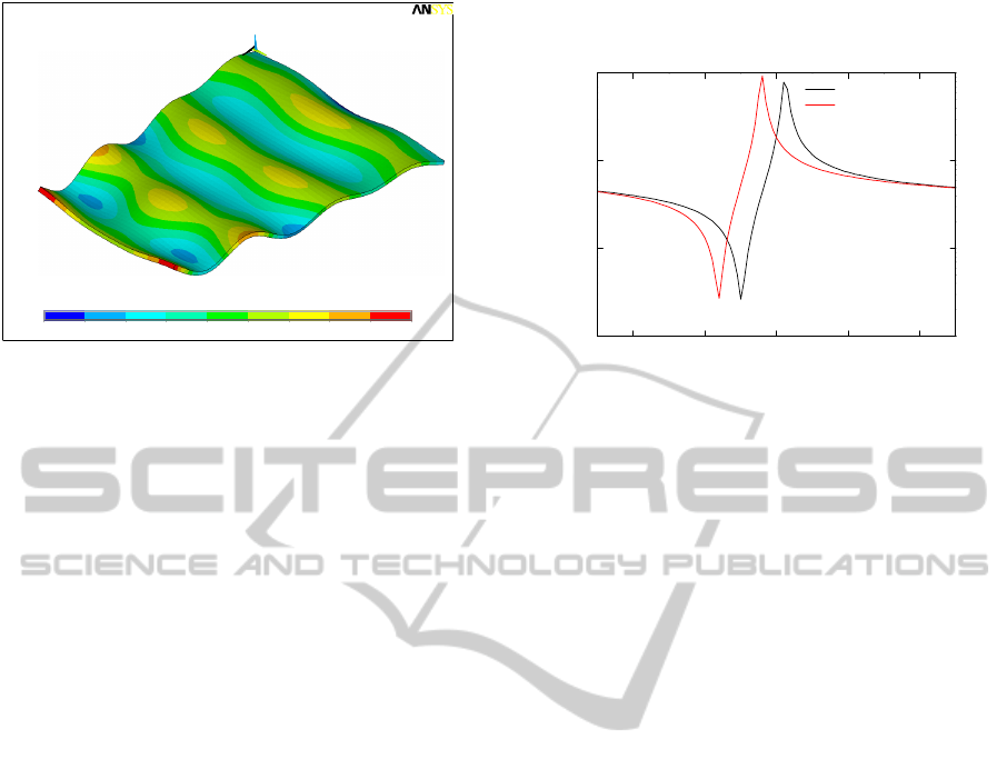
Figure 1: Foil displacement field (arbitrary units) at its
first ultrasonic bending mode (25044 Hz).
3 THE DESIGN OF THE
LANGEVIN TRANSDUCER
The Langevin transducer is basically composed of
two, or more, piezoceramic disks electrically
connected in parallel, sandwiched between two
metal masses (Langevin, 1924). It can be excited to
resonate in length–extensional mode at low
frequency, avoiding the need of high driving
voltages. The structure is usually pre stressed in
order to increase the mechanical strength of
piezoceramic elements and is suitable to absorb high
electrical power. In our case the transducer is
composed by 4 piezoceramic rings (Pz 26, by
Ferroperm Piezoceramics A/S, Kvistgaard,
Denmark) with a thickness of 1 mm, an outer
diameter of 20 mm and an inner diameter of 3.8 mm;
imposing a resonance of 25 kHz, by classical 1–D
analytical models (Zelenka, 1986) we computed that
the thickness of both the front and back steel masses
is 44.6 mm.
The 4 piezoceramic rings are electrically connect
in parallel by means of 4 copper rings (0.35 mm
thick and with the same diameters of piezoceramic
disks) placed between them. In order to verify if the
presence of the copper rings can be neglected in the
actuator design, we computed by ANSYS the
electrical input impedance Z
i
of the Langevin with
and without these rings; in Fig. 2 is shown the Z
i
amplitude computed in the two cases in a frequency
range around the foil resonance. As it can be seen,
the presence of the copper rings is not negligible: the
resonance and antiresonace frequencies both shift of
about 600 Hz (the 2.4 % of the resonance
frequency); in the next steps of the transducer design
the presence of copper contact rings must be
accounted.
Figure 2: Electrical input impedance of the Langevin
transducer computed by ANSYS taking (in red), or not (in
black) the copper contact rings into account.
In order to amplify the displacement on the
actuator front face various solutions can be used;
among these, sectional ultrasonic concentrators,
made from rods of variable and constant cross
section, are those that have been mainly exploited in
applications. Basically, sectional concentrators are
designed to resonate in length–extensional mode at
the same frequency of the Langevin transducer and
the displacement amplification depends on the ratio
between the back and the front sections. Sectional
concentrators have been widely analyzed by
Merkulov (Merkulov, 1957) and Kharitonov
(Merkulov, Kharitonov, 1959) for several shapes
(conical, exponential and catenoidal). These authors
concluded that the maximum displacement
amplification is achieved for a stepped horn, when
the two sections are both one-quarter wavelength
(λ/4) long; in this case, the amplification factor is
equal to the ratio between the areas of the two end
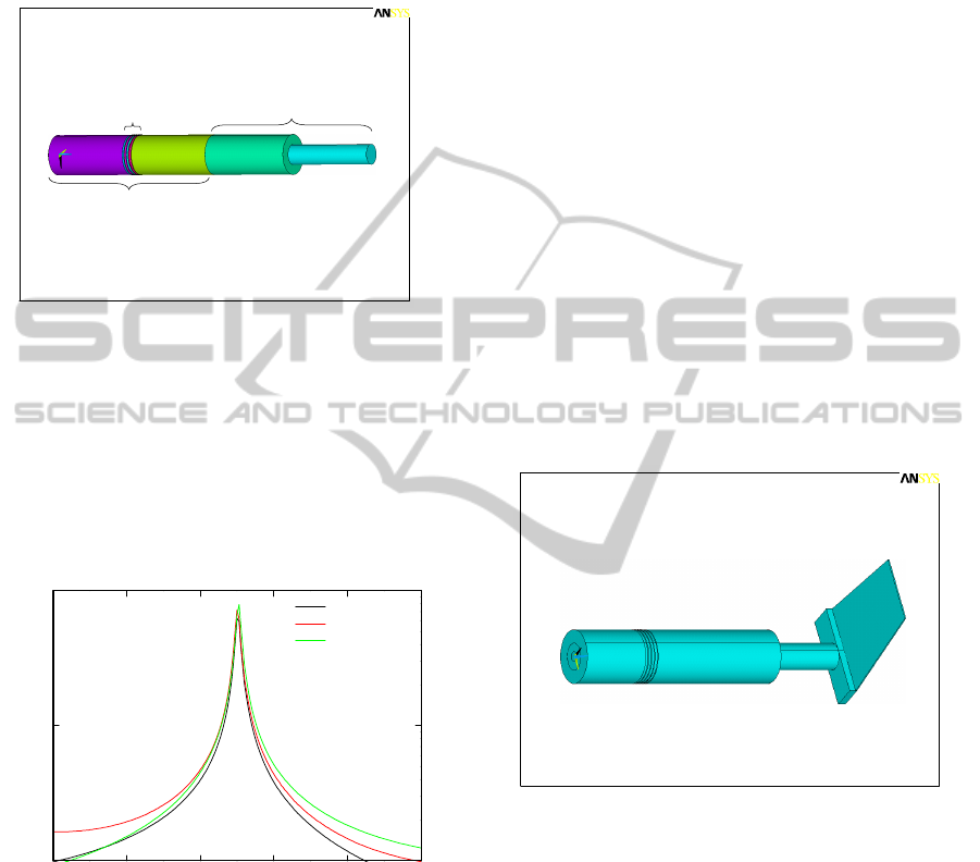
sections. By using this design criterion, the actuator
total length is therefore λ: λ/2 of the Langevin
transducer plus λ/2 of the stepped horn displacement
amplifier. For the design of the displacement
amplifier we just decided to use a stepped horn
device (the whole actuator is shown in Fig. 3); the
sections of the amplifier are both 48.6 mm long, the
thinner section has a diameter of 10 mm while the
other has the same diameter of the other Langevin
components.
The main problem of this kind of actuator is its
total encumbrance: in the present case the whole
length is 194.4 mm. In order to reduce the
encumbrance we designed a device whose total
length is λ/2 at the operating frequency (≈
25 kHz):
it is composed by the same 4 Pz 26 piezoceramic
1
MN
MX
X Y
Z
-43.219
-32.941
-22.662
-12.384
-2.105
8.173
18.452
28.73
39.009
49.287
JUL 2 2010
13:07:54
NODAL SOLUTION
STEP=1
SUB =30
FREQ=25044
UZ (AVG)
RSYS=0
DMX =49.496
SMN =-43.219
SMX =49.287
22 24 26 28 30
10
100
1000
10000
without copper rings
with copper rings
|Z
i
| [Ω]
f [kHz]
BIODEVICES 2011 - International Conference on Biomedical Electronics and Devices
164
rings and the same copper contacts of the λ actuator,
while the length of the two masses is 26.3 mm, and
the two sections of the displacement amplifier are 29
mm long; with this choice the actuator total
encumbrance is 116 mm, more than 40 % smaller.
Figure 3: Schematic view of the Langevin actuator with
the classical stepped horn displacement amplifier.
In order to compare the performances of the two
solutions we computed by ANSYS the vertical
component of the displacement, u
z
in the center of
the front face for both transducers; in Fig. 4 the |u
z
|
amplitudes computed in the two cases are compared
with |u
z
| computed for the Langevin without
displacement amplifier.
Figure 4: Displacement computed by ANSYS at the center
of the front face of the Langevin actuator (in black), of the
λ actuator (in red) and of the λ/2 actuator (in green).
As it can be seen the resonance frequencies are
practically the same, while the λ/2 transducer shows
a displacement amplitude a bit greater than that of
the λ one; this result within the device encumbrance
let us to prefer the λ/2 device. The only problem of
this solution is that in this case the node of u
z
is not
in the piezoceramic zone; this problem will be
accounted in the design of the whole actuator.
4 THE DESIGN OF THE WHOLE
ACTUATOR
In order to mechanically connect the front face of
the displacement amplifier to the vibrating foil, an
ad hoc “support” is needed. This support is a
parallelepiped whose length is equal to the radius of
the front face of the displacement amplifier, while
the width is constrained to be equal to that of the
vibrating foil. The only degree of freedom of this
element is therefore its thickness: it cannot be too
small in order to avoid flexural vibrations in the foil
in the width direction; on the other hand it cannot be
too large to don’t excessively charge the Langevin
and therefore to weaken its mechanical excitation.
By using ANSYS we designed the thickness of the
support in order to maximize the amplitude of the
flexural vibration in the foil: the best results were
obtained with a support thickness of 3 mm. In Fig. 5
is shown the geometry of the whole transducer: it is
composed by the Langevin actuator, the stepped
horn displacement amplifier, the mechanical support
and the vibrating foil.
Figure 5: Geometry of the proposed actuator.
For applications in dermatological aesthetic, the
actuator must be designed to maximize the
amplitude of the vibrations in the foil; we analyzed
the proposed actuator by ANSYS first of all to
evaluate the resonance frequency, to verify that the
displacement field in the foil is flexural and to
maximize the foil displacement. In Fig. 6 is shown
the amplitude of |u
z
| computed by ANSYS at the
center of the foil free edge. As it can be seen, the
maximum of the displacement is obtained at 26.1
kHz; this shift in respect to the resonance
frequencies of both the Langevin (with the
displacement amplifier) and the foil, and the ripple
in the explored frequency range are due the support
20 22 24 26 28 30
1
10
100
Langevin
λ actuator
λ/2 actuator
|u
z
| [μm]
f [kHz]
1
X
Y
Z
SEP 11 2009
16:25:33
VOLUMES
TYPE NUM
1
X
Y
Z
SEP 11 2009
16:13:00
VOLUMES
VOLU NUM
Piezoceramics
Dis
p
lacement am
p
Lan
g
evi
n
A PIEZOELECTRIC ACTUATOR, BASED ON A LANGEVIN-TYPE TRANSDUCER, FOR DERMATOLOGICAL
AESTHETIC APPLICATIONS
165
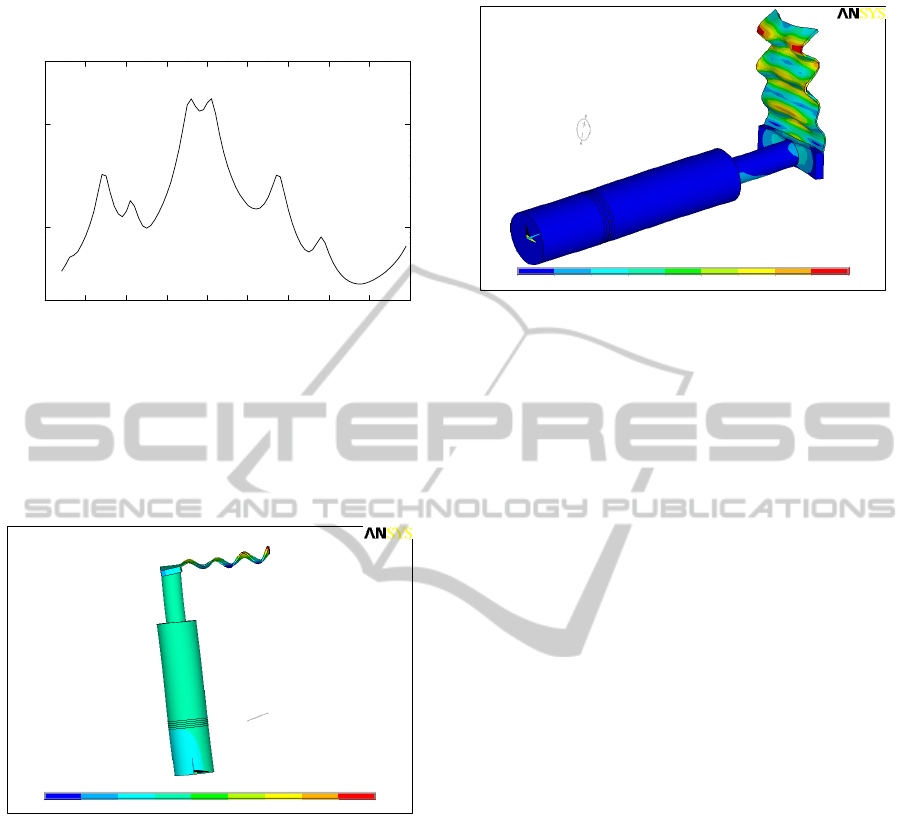
and the superposition of many modes that are
strongly coupled together.
Figure 6: Amplitude of the displacement computed by
ANSYS at the centre of the foil free edge.
In order to verify if the foil vibration at the
resonance (26.1 kHz) is a flexural vibration we
computed the displacement field in the actuator at
this frequency; in Fig. 7 is shown the obtained result.
Figure 7: Displacement field (in meters) in the proposed
actuator computed at 26.1 kHz.
As it can be seen, an uniform bending vibration
is excited in the foil and the displacements have their
maximum amplitude at the unconstrained edge. The
displacements in the "Langevin" actuator are
negligible with respect to those of the foil, and
therefore a good stiffness of the whole structure is
expected.
Finally, in order to verify the stiffness of the
proposed structure, the stresses in the actuator have
been computed by supplying it at 26.1 kHz with a
sinusoidal voltage signal of 250 V in amplitude. In
Fig. 8 the field of stresses along the structure is
shown.
Figure 8: Stress field (in Pascal) computed supplying the
proposed actuator at 26.1 kHz with a sinusoidal voltage
generator of 250 V.
The weaker actuator part is the zone of contact
between foil and support; as it can be seen, only in a
small area around the centre the stress reaches a
value of about 100 MPa, whilst in the remaining
contact areas it is below 76 MPa and even sinks
below 13 MPa in the external zones; these values are
far from the yield point, of about 500 MPa in the
steel of the support and the foil. Even the stress on
the piezoelectric ceramics is small: below 15 MPa;
this avoids depolarisation problems (the
depolarization limit is 30 MPa). Finally, the
maximum of the stress on the foil doesn’t exceed
140 MPa and therefore also in this zone it is far from
the limit value in the steel.
5 CONCLUSIONS
In this paper a piezoelectric actuator able to excite a
bending motion in a steel foil is described; the active
part of the actuator is a piezoelectric Langevin–type
transducer soliciting the foil at one edge. The
resonance modes of the foil were analyzed by
ANSYS in order to identify bending modes at an
ultrasonic resonance frequency. The second step was
the design of a Langevin transducer with the same
resonance frequency: by means of ANSYS we
designed a transducer composed by 4 piezoceramic
rings, electrically connected in parallel, a front and a
back mass and a displacement amplifier realized by
means of a classical stepped horn ultrasonic
concentrator. We compared the performance of this
actuator with that of a Langevin with the same
components but with a total length equal to λ/2 at the
resonance frequency; the performance of this device
is a bit greater than that of the other, with the
advantage of an encumbrance about one half. The
22 23 24 25 26 27 28 29 30 31
10
100
|u
z
| [
μ
m]
f [kHz]
1
MN
MX
X
Y
Z
-.129E-04
-.887E-05
-.487E-05
-.878E-06
.312E-05
.711E-05
.111E-04
.151E-04
.191E-04
.231E-04
JAN 29 2007
11:42:36
NODAL SOLUTI ON
STEP=1
SUB =38
FREQ=26100
REAL ONLY
UZ (AV G)
RSYS=0
DMX =.232E-0 4
SMN =-.129E- 04
SMX =.231E-0 4
1
MN
MX
X
Y
Z
155167
.153E+08
.305E+08
.457E+08
.608E+08
.760E+08
.912E+08
.106E+09
.122E+09
.137E+09
JAN 29 2007
11:31:33
NODAL SOLUTIO N
STEP=1
SUB =38
FREQ=26100
REAL ONLY
SINT (AVG )
DMX =.232E-04
SMN =155167
SMX =.137E+09
BIODEVICES 2011 - International Conference on Biomedical Electronics and Devices
166

connection between the foil and the displacement
amplifier is realized by means of an ad hoc prismatic
steel “support”. The design of whole actuator was
optimized by means of ANSYS, with the purpose to
maximize the bending displacement at the free edge
of the foil. Finally, in order to test the actuator
stiffness, we computed the stresses in the structure in
operating conditions and we verified that their
values in any point are far from the material limits.
The next step will be the realization of an
actuator prototype in order to experimentally verify
its performance and to refine the design.
The actuator design criteria are the basis of an
international patent (Lamberti et al., 2008).
REFERENCES
Langevin P., French Patent n. 503913 (29/5/1929), n.
505703 (5/8/1920), n. 575435 (30/7/1924).
Zelenka J., 1986. Piezoeletric resonator and their
applications, Elsevier, New York.
Merkulov L. G., 1957, Design of ultrasonic concentrators.
In Sov. Phys. Acoust., 3, pp. 246–255.
Merkulov L. G., Kharitonov A. V., 1959, Theory and
analysis of sectional concentrators. In Sov. Phys.
Acoust., 5, pp. 183–190.
Lamberti N., Casacchia G., Ardia L., Caputo A., 2008,
Actuator with interchangeable bending-vibrating foils,
based on a langevin-type transducer, International
Patent, PCT/IT2008/000431.
A PIEZOELECTRIC ACTUATOR, BASED ON A LANGEVIN-TYPE TRANSDUCER, FOR DERMATOLOGICAL
AESTHETIC APPLICATIONS
167
