
A MATHEMATICAL MODEL FOR THE ENHANCED
CYTOPLASMIC TRANSPORT
How to Get (Faster) to the Nucleus
Luna Dimitrio
Dipartimento Me.Mo.Mat., Universit
`
a degli Studi “La Sapienza” di Roma, Rome, Italy
INRIA Rocquencourt, Domaine de Voluceau, Rocquencourt, France
Roberto Natalini
Istituto per le Applicazioni del Calcolo “M. Picone”, Consiglio Nazionale delle Ricerche, Rome, Italy
Luciano Milanesi
Istituto di Tecnologie Biomediche, Consiglio Nazionale delle Ricerche, Segrate, Milano, Italy
Keywords:
Cytoplasmic enhanced transport, Microtubules, Partial differential models.
Abstract:
We consider a simple model for signal transport in the cytoplasm. Following some recent experimen-
tal evidences, the standard diffusion model is supplemented by advection operated through an attache-
ment/detachement mechanism along microtubules. This model is given by a system of partial differential
equations which are cast in different dimensions and connected by suitable exchange rules. A numerical
scheme is introduced and some simulations are presented and discussed to show the performances of our
model.
1 INTRODUCTION
A key process in cell’s life is intra-cellular transport.
Eukaryotes have a highly compartmentalized struc-
ture: different processes are performed in specific
compartment named organelles. The largest organelle
is of course the nucleus, where DNA is stored and
protected. Proteins need to get into the nucleus to ac-
tivate specific processes and to exchange information.
There are different mechanisms that the cell can ex-
ploit to this purpose. For example proteins can move
from a region of higher concentration to one of lower
concentration: this process is known as facilitated
transport. The concentration gradient that allows this
kind of transport is created by the protein Ran that in
its GDP and GTP bound form operates in import and
export of proteins from and to the nucleus. Ran has
an asymmetric distribution within the cell: the GTP
bound form is abundant in the nucleus while the cyto-
plasm is rich of Ran•GDP. The Ran gradient operates
in the transport mechanism giving the directionality
to transport. Other possibilities for nuclear proteins
import have been explored and different mechanisms
have been proved to cooperate in transport (for a re-
view see (Wagstaff and Jans, 2009)). For example
some specific proteins like p53, p38 or the parathyroid
hormone-related protein (PTHrP) use microtubules to
facilitate their way towards the nucleus (Giannakakou
et al., 2002; Roth et al., 2007; Lam et al., 2002; Gong
et al., 2010).
We are interested in this kind of transport where
proteins use microtubules as further support through
their way to the nucleus. In this work we would like
to point out the importance of microtubule-assisted
transport for an efficient nuclear accumulation of
NLS-proteins. To further motivate this work let us
remark that objections were raised against the theory
that diffusion alone is the only mechanism operating
in transport (Agutter et al., 1995). For example cy-
toplasmic location of enzymes in signaling cascades
(Kholodenko, 2009) is fundamental for the efficient
diffusion of the signal within the cell.
We present here a spatial model based on PDEs
whose variables are the proteins concentrations and
39
Dimitrio L., Natalini R. and Milanesi L..
A MATHEMATICAL MODEL FOR THE ENHANCED CYTOPLASMIC TRANSPORT - How to Get (Faster) to the Nucleus.
DOI: 10.5220/0003135700390046
In Proceedings of the International Conference on Bioinformatics Models, Methods and Algorithms (BIOINFORMATICS-2011), pages 39-46
ISBN: 978-989-8425-36-2
Copyright
c
2011 SCITEPRESS (Science and Technology Publications, Lda.)

we restrict our study to an area assumed to be influ-
enced by a single microtubule. We want to represent
two different transport mechanisms: diffusion and ac-
tive transport along microtubules. Since we are inter-
ested in transport of nuclear protein, we will look at
transport along microtubules in a single direction, i.e.
towards the nucleus.
For a matter of simplicity we chose to describe
only the essential molecular pathways and we get a
simple model with two species concentrations and the
concentration of the attached particles, represented by
a third equation.
Moreover as a distinguishing feature we model the
transported cargo concentration on the microtubule
by a 1-dimensional process, and we let the diffusive
molecules lie on the two dimensional domain. This
multidimensional approach is largely used in blood-
flow numerical modeling in order to describe large
systems of vessels: they give the possibility to switch
from 3D models to 1D or 0D representations and re-
create dynamics that involve different space scales in
large vessels networks. This choice consents also a
gain in computational time, see for instance (Passerini
et al., 2009).
1.1 Microtubules Enhanced Transport
Microtubules (MTs) are filaments composed by tubu-
lin dimers that constitute the cytoskeleton together
with actin filaments and intermediate filaments. They
are organized in a radial structure pointing towards
a common region, the Microtubule Organizing Cen-
ter (MTOC), from which they nucleate. The MTOC
is set near the nucleus so that microtubules irradiate
from the cell center to the cell periphery. Moreover
they have a polarity: a plus end toward the cell pe-
riphery and a minus at the cell center.
Microtubules are involved in many cellular pro-
cess, namely they are responsible for vesicles and or-
ganelles transport within the cell, they play an impor-
tant role during mitosis and are required in cellular
motility. Here, we are interested in investigating the
ability of microtubules to enhance intracellular trans-
port. It is known that viruses use these highways to
get close to the nucleus (Campbell and Hope, 2003)
and that vesicles and organelles, as mitochondria, are
transported within the cytoplasm by motor proteins
bound to microtubules.
As said before recent studies demonstrated that
some proteins use this network to facilitate their way
towards the perinuclear region (Giannakakou et al.,
2002; Roth et al., 2007; Lam et al., 2002; Gong et al.,
2010; Salman et al., 2005). Regulation of the cel-
lular machinery need an efficient transport machin-
ery and the cytoskeleton that structure the entire cy-
toplasm seems to be a natural candidate to cover this
role (Wagstaff and Jans, 2009; Campbell and Hope,
2003). In order to move close to the nuclear en-
velope, viruses, organelles and some NLS-proteins
take advantage of the microtubule network. In some
cases molecules can associate to this structure to pre-
vent their nuclear accumulation (Campbell and Hope,
2003). Active transport along the MTs is permitted by
binding to a motor protein, which possesses a mech-
anism for moving along the MT at a speed of about
0.5 to 1µms
−1
(Smith and Simmons, 2001; N
´
ed
´
elec
et al., 2001). Two families of motor proteins associate
to the MTs: dynein, which permits transport from the
plus end to the minus end, and kinesin, which trans-
ports in the opposite direction. Here we just focus our
model on the dynein motor.
2 A SIMPLE MODEL
A few mathematical models exist to represent these
different employs of MTs (Cangiani and Natalini,
2010; Smith and Simmons, 2001; Dinh et al., 2007)
but most of them are one dimensional models and do
not consider the effective position of single filaments.
Recently Cangiani and Natalini proposed in (Can-
giani and Natalini, 2010) a three dimensional model
of nucleocytoplasmic transport which takes into ac-
count all the signalling pathway of protein import.
Their results show the dependence on MT-enhanced
transport for the optimality of nuclear import, as re-
ported in Roth (Roth et al., 2007).
In this paper we propose a model that could re-
produce microtubule-based transport towards the nu-
cleus to highlight the importance of this mechanism
for the efficiency of nuclear import. To this goal we
suggest a simplified bi-dimensional model of cyto-
plasmic transport taking into account as few kinetic
processes as possible.
Unlike other models we represent the position of
a single MT filament. For the time being we do not
want to model the crossing of the nuclear envelope
and we restrict our study to the representation of a
single domain that called Ω (see Figure 1). Further-
more we will consider only the kinetics of the free
cargo and of the cargo-dynein complex without look-
ing at the whole import pathway. We model this sys-
tem so that transported particles obey to a one dimen-
sional equation, while diffusing particles are in a two
dimensional domain. We restrict our study to an area
that we suppose influenced by a single microtubule.
Finally, via the choice of periodic boundary condi-
tion on the longer side of our domain, we make the
BIOINFORMATICS 2011 - International Conference on Bioinformatics Models, Methods and Algorithms
40
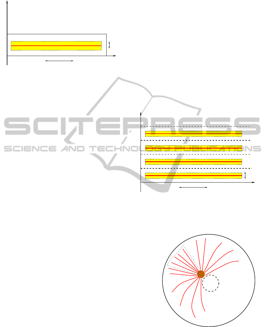
10µ m
IxJ
Ω
Γ
Γ
1
3
4
y
Γ
y
0
−δ
y
0
+δ
x
In
y
0
200nm
Γ
2
x
x
Fi
Figure 1: Area of the cytoplasm where intracellular trans-
port is modeled: Ω = [0, L
x
] × [0,L
y
]. The yellow rectangle
(I ×J = [x
In
,x
Fi
] × [y
0
− δ,y
0
+ δ]) represents the attraction
area of the microtubule filament, the red strip is the micro-
tubule, positioned in y
0
.
assumption that MTs are homogeneously distributed
inside the cell.
2.1 A Model for Proteins
We consider only the kinetic equations of two pro-
teins: a generic NLS-protein (cargo C) that has to
be transported to the nucleus and the motor protein
dynein (D). Dynein is a molecular motor that move
along microtubules in the direction of cell nucleus
(Mallik et al., 2005). We suppose dynein concentra-
tion constant and uniformly distributed. Cargo dif-
fuses freely in the cytosol and bind to dynein, so that
facilitated diffusion can be achieved. If the dynein-
cargo complex (P
f
) reach the attraction area (see Fig-
ure 1) of the microtubule filament, they can bind to-
gether, so attachment and detachment to the MT is
seen as a kinetic process.
Once the complex (P
t
) moves on the microtubule,
it has a steady velocity of about 1µms
−1
as reported,
for example, in (Nan et al., 2005). The complex
bound to the MT has a certain probability k
−1
to de-
tach from the filament. However at the end of the mi-
crotubule it is necessarily released near the boundary
of the considered region. Here we specify the kinetic
reactions:
D +C
k
k
−
P
f
,
P
f
k
1
k
−1
P
t
on IxJ.
The last reaction occurs only in the area of attrac-
tion of the microtubule, here denoted as IxJ (see Fig-
ure 1). Here I = [x
In
,x
Fi
] is the actual length of the
microtubule and J = [y
0
−δ,y
0
+δ] is the width of the
filament positioned in y
0
.
2.2 The Mathematical Model
We want to represent mathematically the molecular
pathways presented above, localizing them in the con-
sidered domain Ω : in this way we get a system of
partial differential equations. We imagine the domain
to be the cytoplasmic area surrounding a single fila-
ment of microtubule. We assume that the structure of
the MTs network is homogeneous within the cell and
represent this choice via periodic boundary condition
on the long sides of the domain, Γ
1
and Γ
3
.
We use classic laws to represent every process:
Mass Action Law for kinetic reactions, Fick’s law
of free diffusion for species concentrations diffusion
and active transport for the particle bound to the mi-
crotubule. Let u = [C], v = [P
f
], w = [P
t
] be respec-
10µ m
200nm
Figure 2: Periodic boundary conditions on the long side of
the domain (see figure 1) in equation 1 make the cell an ho-
mogenous environment. This means that the strip where we
model the system is only a “zoom” on a single microtubule.
We suppose that the same reactions take place in the rest of
the cell.
nucleus
MTOC
Figure 3: Schematic model of the cell with its microtubules
structure.
tively the cargo, cargo+dynein and transported com-
plex concentrations, d
u
and d
v
the diffusion coeffi-
cients of the u and v species respectively and c the
A MATHEMATICAL MODEL FOR THE ENHANCED CYTOPLASMIC TRANSPORT - How to Get (Faster) to the
Nucleus
41

∂u
∂t
= d
u
∆u − kd
dyn
u + k
−
v, in Ω,
∂v
∂t
= d
v
∆v + kd
dyn
u − k
−
v − k
1
v
IxJ
+ k
−1
w
IxJ
|J|
+ c(δ
x
Fi
− δ
x
In
)w
IxJ
|J|
, in Ω,
∂w
∂t
+ c
∂w
∂x
= −k
−1
w + k
1
R
J
vdy, in ]x
In
,x
Fi
[,
(1)
velocity for the transported particle. Dynein concen-
tration is supposed to be constant and is denoted by
[D] = d
dyn
.
Under the previous assumptions the u and v
species satisfy a reaction-diffusion equation, while w
is controlled by a convection equation modeling the
transport along the microtubule with a steady veloc-
ity c. The model we get is equation 1, where δ
x
0
in the equation for v stands for the Dirac mass in
x
0
= x
In
,x
Fi
. The term c(δ
x
Fi
− δ
x
In
)w
IxJ
represents
the contribution due to the outgoing flux of the trans-
ported particles at the end of the MT filament and it
guarantees conservation of the mass. We also impose
the boundary conditions:
∂u
∂n
= 0,
∂v
∂n
= 0, on Γ
4
,
d
u
∂u
∂n
+ p
u
u = 0, d
v
∂v
∂n
+ p
v
v = 0, on Γ
2
,
w(x
In
) = 0.
As said before, the boundary conditions on Γ
1
and Γ
3
for u and v are periodic, i.e. we suppose that for every
t u|
Γ
1
= u|
Γ
3
, respectively v (see figure 2). We as-
sume that proteins cannot cross the membrane layer
on Γ
4
using a Neumann homogeneous boundary con-
dition, but we suppose that on Γ
2
there is an outgoing
flow proportional to the species concentration. For
the transported cargo we suppose that there is not an
upcoming flux at the beginning of the microtubule.
We remark that the two first equations lie in a two
dimensional domain: u = u(x,y,t) and v = v(x,y,t)
represent the species concentration per unit volume
at time t in (x, y) ∈ Ω. The equation for w is one
dimensional and the cargo concentration can move
only in one direction along the filament, positioned
at [x
In
,x
Fi
] × {y
0
} ⊂ Ω.
In our model, to point out the difference in the type
of transport mechanisms, we consider the MT depen-
dent transport to be 1D and describe diffusion as a bi-
dimensional event. With this approach we couple the
two mechanisms considered and model them at two
different levels. In this way we get an interconnected
system that relies on the two processes but empha-
sizes the features of each type of transport.
A concentration gradient that allows diffusion in
the whole domain, and active transport directed to-
wards the nucleus and localized near the microtubule.
3 SCHEME
In this section we will propose a numerical scheme in
order to solve the system presented above.
Let us introduce a space discretization of the x and
y axis. Our domain Ω is the rectangle [0,L
x
] × [0, L
y
]
(fig: 1). We denote by ∆x, ∆y the discretization steps
in the x and y directions respectively and we divide
the intervals [0,L
x
] and [0, L
y
] in N
x
+ 1 and N
y
+ 1
points. The mesh points will be (x
i
,y
j
) = (i∆x, j∆y)
with 0 ≤ i ≤ N
x
+1, 0 ≤ j ≤ N
y
+1. Let ∆t be the time
discretization step and t
n
the n
th
step, i.e. t
n
= n∆t,
n ∈ N. According to these notations u
n
i, j
will be the
approximation of the solution of u in (x
i
,y
j
) at time
t
n
and respectively v
n
i, j
and w
n
i
denote the approxima-
tions of v and w. We remark that w lies in [x
In
,x
Fi
]
so w
n
i
is well defined only for certain values of i, in
particular we need x
In
/∆x ≤ i≤ x
Fi
/∆x.
We first solve the third equation of the system. We
discretize the transport contribution by using an up-
wind scheme enhanced by a TDV flux limiter (Sweby,
1984). The right hand side is made by two parts. The
term −k
−1
w is stiff, and it will be approximated by
an implicit discretization. For the other source term
F :=
R
J
v(x
i
,y)dy
|J|
, we used an upwinding scheme (Roe,
1981), which improve the resolution near the asymp-
totic states, and besides, we approximated the integral
using a trapezoidal rule. Summing up these consid-
erations, we obtain a scheme for w (equation 2). In
this equation ν = c
∆t
∆x
and we put r
i+1/2
=
w
n
i−1
−w
n
i−2
w
n
i
−w
n
i−1
and r
i−1/2
=
w
n
i+1
−w
n
i
w
n
i
−w
n
i−1
, while φ is a flux limiter func-
tion (minmod in our simulations, see again (Sweeby,
1984)).
We use a IMEX midpoint scheme (Briani et al.,
2007), to solve numerically the reaction-diffusion
system (see equations: 3, 4), where
δ
2
x
u
(1)
∆x
2
=
u
(1)
i+1, j
− 2u
(1)
i, j
+ u
(1)
i−1, j
∆x
2
and
motor velocity for the transported particle. Dynein
concentration is supposed to be constant and is de-
noted by [D] = d
dyn
.
Under the previous assumptions the u and v
species satisfy a reaction-diffusion equation, while w
is controlled by a convection equation modeling the
transport along the microtubule with a steady veloc-
ity c. The model we get is equation 1, where δ
x
0
in the equation for v stands for the Dirac mass in
x
0
= x
In
,x
Fi
. The term c(δ
x
Fi
− δ
x
In
)w
IxJ
represents
the contribution due to the outgoing flux of the trans-
ported particles at the end of the MT filament and it
guarantees conservation of the mass. We also impose
the boundary conditions:
∂u
∂n
= 0,
∂v
∂n
= 0, on Γ
4
,
d
u
∂u
∂n
+ p
u
u = 0, d
v
∂v
∂n
+ p
v
v = 0, on Γ
2
,
w(x
In
) = 0.
As said before, the boundary conditions on Γ
1
and Γ
3
for u and v are periodic, i.e. we suppose that for every
t u|
Γ
1
= u|
Γ
3
, respectively v (see figure 2). We as-
sume that proteins cannot cross the membrane layer
on Γ
4
using a Neumann homogeneous boundary con-
dition, but we suppose that on Γ
2
there is an outgoing
flow proportional to the species concentration. For
the transported cargo we suppose that there is not an
upcoming flux at the beginning of the microtubule.
We remark that the two first equations lie in a two
dimensional domain: u = u(x,y,t) and v = v(x,y,t)
represent the species concentration per unit volume
at time t in (x,y) ∈ Ω. The equation for w is one
dimensional and the cargo concentration can move
only in one direction along the filament, positioned
at [x
In
,x
Fi
] × {y
0
} ⊂ Ω.
In our model, to point out the difference in the type
of transport mechanisms, we consider the MT depen-
dent transport to be 1D and describe diffusion as a bi-
dimensional event. With this approach we couple the
two mechanisms considered and model them at two
different levels. In this way we get an interconnected
system that relies on the two processes but empha-
sizes the features of each type of transport.
A concentration gradient that allows diffusion in
the whole domain, and active transport directed to-
wards the nucleus and localized near the microtubule.
3 SCHEME
In this section we will propose a numerical scheme in
order to solve the system presented above.
Let us introduce a space discretization of the x and
y axis. Our domain Ω is the rectangle [0,L
x
] × [0, L
y
]
(fig: 1). We denote by ∆x, ∆y the discretization steps
in the x and y directions respectively and we divide
the intervals [0, L
x
] and [0, L
y
] in N
x
+ 1 and N
y
+ 1
points. The mesh points will be (x
i
,y
j
) = (i∆x, j∆y)
with 0 ≤ i ≤ N
x
+1, 0 ≤ j ≤ N
y
+1. Let ∆t be the time
discretization step and t
n
the n
th
step, i.e. t
n
= n∆t,
n ∈ N. According to these notations u
n
i, j
will be the
approximation of the solution of u in (x
i
,y
j
) at time
t
n
and respectively v
n
i, j
and w
n
i
denote the approxima-
tions of v and w. We remark that w lies in [x
In
,x
Fi
]
so w
n
i
is well defined only for certain values of i, in
particular we need x
In
/∆x ≤ i≤ x
Fi
/∆x.
We first solve the third equation of the system. We
discretize the transport contribution by using an up-
wind scheme enhanced by a TDV flux limiter (Sweby,
1984). The right hand side is made by two parts. The
term −k
−1
w is stiff, and it will be approximated by
an implicit discretization. For the other source term
F :=
R
J
v(x
i
,y)dy
|J|
, we used an upwinding scheme (Roe,
1981), which improve the resolution near the asymp-
totic states, and besides, we approximated the integral
using a trapezoidal rule. Summing up these consid-
erations, we obtain a scheme for w (equation 2). In
this equation ν = c
∆t
∆x
and we put r
i+1/2
=
w
n
i−1
−w
n
i−2
w
n
i
−w
n
i−1
and r
i−1/2
=
w
n
i+1
−w
n
i
w
n
i
−w
n
i−1
, while φ is a flux limiter func-
tion (minmod in our simulations, see again (Sweeby,
1984)).
We use a IMEX midpoint scheme (Briani et al.,
2007), to solve numerically the reaction-diffusion
system (see equations: 3, 4), where
δ
2
x
u
(1)
∆x
2
=
u
(1)
i+1, j
− 2u
(1)
i, j
+ u
(1)
i−1, j
∆x
2
and
BIOINFORMATICS 2011 - International Conference on Bioinformatics Models, Methods and Algorithms
42

(1 + ∆tk
−1
)w
n+1
i
= w
n
i
−
ν
2
(w
n
i+1
− w
n
i−1
) −
ν
2
(1 − ν)[φ(r
i+1/2
)(w
n
i+1
− w
n
i
)
+φ(r
i−1/2
)(w
n
i
− w
n
i−1
)] +
1
2
∆tk
1
(F
n
i
+ F
n
i−1
).
(2)
u
(1)
i, j
= u
n
i, j
+ d
u
∆t
2
(
δ
2
x
u
(1)
∆x
2
+
δ
2
y
u
(1)
∆y
2
) − kd
dyn
∆t
2
u
(1)
i, j
+ k
−
∆t
2
v
n
i, j
,
v
(1)
i, j
= v
n
i, j
+ d
v
∆t
2
(
δ
2
x
v
(1)
∆x
2
+
δ
2
y
v
(1)
∆y
2
) − k
−
∆t
2
v
(1)
i, j
+ kd
dyn
∆t
2
u
n
i, j
,
(3)
u
n+1
i, j
= u
n
i, j
+ d
u
∆t(
δ
2
x
u
(1)
∆x
2
+
δ
2
y
u
(1)
∆y
2
) − kd
dyn
∆tu
(1)
i, j
+ k
−
∆tv
(1)
i, j
,
v
n+1
i, j
=
v
n
i, j
+ d
v
∆t(
δ
2
x
v
(1)
∆x
2
+
δ
2
y
v
(1)
∆y
2
) − k
−
∆tv
(1)
i, j
+ kd
dyn
∆tu
(1)
i, j
−k
1
v
n
i, j
+ k
−1
w
n+1
i
|J|
if i, j ∈ I × J ,
v
n
i, j
+ ∆t(
δ
2
x
v
(1)
∆x
2
+
δ
2
y
v
(1)
∆y
2
) − k
−
∆tv
(1)
i, j
+ kd
dyn
∆tu
(1)
i, j
− k
1
v
n
i, j
+k
−1
w
n+1
i
|J|
+ cw
n+1
i
if (i, j)|(x
i
,y
j
) = (x
Fi,
y
0
)
v
n
i, j
+ d
v
∆t(
δ
2
x
v
(1)
∆x
2
+
δ
2
y
v
(1)
∆y
2
) − k
−
∆tv
(1)
i, j
+ kd
dyn
∆tu
(1)
i, j
otherwise.
(4)
δ
2
y
u
(1)
∆y
2
=
u
(1)
i, j+1
− 2u
(1)
i, j
+ u
(1)
i, j−1
∆y
2
(respectively for v). since u and v satisfy mixed
boundary conditions on Γ
2
and Neumann boundary
conditions on Γ
4
we use the second order derivative
approximation to calculate the boundary values. We
use this second order approximation
∂u
∂n
(0,y
j
) =
1
2∆x
(−3u
n
0, j
+ 4u
n
1, j
− u
n
2, j
),
to yield:
u
n
0, j
= (
4
3
u
n
1, j
−
1
3
u
n
2, j
).
We also discretize:
∂u
∂n
(L
x
,y
j
) =
1
2∆x
(3u
n
N
x
+1, j
− 4u
n
N
x
, j
+ u
n
N
x
−1, j
),
which gives
u
n
N
x
+1, j
=
d
u
d
u
+ 2∆xp
u
(4u
n
N
x
, j
− u
n
N
x
−1, j
).
Similarly we calculate the numerical approximation
of v on the boundary.
3.1 Numerical Experiments
In this section we will do some numerical experi-
ments and we will analyze the order of accuracy of the
scheme proposed. We will solve the system and eval-
uate the differences of solutions at the final time T=2.
To do this we will change the space step and calculate
the L
1
norm of the difference between numerical so-
lutions at different space steps. We put h = ∆x = ∆y
and define the function
γ
f
= log
2
k f
n
(h) − f
n
(h/2)k
1
k f
n
(h/2) − f
n
(h/4)k
1
, (5)
whose values represent the order of accuracy of the
numerical solution. The time step ∆t will change ac-
cordingly to h to satisfy the CFL condition for the
advection equation and the condition for IMEX mid-
point scheme stability, so that in each experiment we
get ∆t = min(h/c,h
4/3
), see (Briani et al., 2007) for
more details.
We fix all the reactions constants and of course the
diffusion constants of the two species:
k = 0.2, k
−
= 0.2, k
1
= 5, k
−1
= 0.2, d
u
= 10,
d
v
= 8, c = 1.
We fixed the motor velocity c = 1, as found in lit-
erature (Mallik et al., 2005), as well as the attach-
ment and detachment rate of cargo and dynein (see
(Cangiani and Natalini, 2010)). The total dynein con-
centration is constant and we assume [D]=1. The
diffusion constants are relative to a given cargo pro-
tein. For example p53-GFP diffusion constant was
estimated to be 15.4µm
2
s
−1
. Table ?? shows the L
1
distances of solutions at different space steps. Table
?? shows the numerical accuracy of the scheme.
4 RESULTS
Using the scheme presented in the previous sec-
tion, we solve numerically the reaction-diffusion-
advection system to calculate the net flux of parti-
cles with and without microtubules. Our purpose is
to show that microtubule activity is a natural support
for intracellular trafficking.
Many proteins have been proved to use the MTs
δ
2
y
u
(1)
∆y
2
=
u
(1)
i, j+1
− 2u
(1)
i, j
+ u
(1)
i, j−1
∆y
2
(respectively for v). since u and v satisfy mixed
boundary conditions on Γ
2
and Neumann boundary
conditions on Γ
4
we use the second order derivative
approximation to calculate the boundary values. We
use this second order approximation
∂u
∂n
(0,y
j
) =
1
2∆x
(−3u
n
0, j
+ 4u
n
1, j
− u
n
2, j
),
to yield:
u
n
0, j
= (
4
3
u
n
1, j
−
1
3
u
n
2, j
).
We also discretize:
∂u
∂n
(L
x
,y
j
) =
1
2∆x
(3u
n
N
x
+1, j
− 4u
n
N
x
, j
+ u
n
N
x
−1, j
),
which gives
u
n
N
x
+1, j
=
d
u
d
u
+ 2∆xp
u
(4u
n
N
x
, j
− u
n
N
x
−1, j
).
Similarly we calculate the numerical approximation
of v on the boundary.
3.1 Numerical Experiments
In this section we will do some numerical experi-
ments and we will analyze the order of accuracy of the
scheme proposed. We will solve the system and eval-
uate the differences of solutions at the final time T=2.
To do this we will change the space step and calculate
the L
1
norm of the difference between numerical so-
lutions at different space steps. We put h = ∆x = ∆y
and define the function
(1 + ∆tk
−1
)w
n+1
i
= w
n
i
−
ν
2
(w
n
i+1
− w
n
i−1
) −
ν
2
(1 − ν)[φ(r
i+1/2
)(w
n
i+1
− w
n
i
)
+φ(r
i−1/2
)(w
n
i
− w
n
i−1
)] +
1
2
∆tk
1
(F
n
i
+ F
n
i−1
).
(2)
u
(1)
i, j
= u
n
i, j
+ d
u
∆t
2
(
δ
2
x
u
(1)
∆x
2
+
δ
2
y
u
(1)
∆y
2
) − kd
dyn
∆t
2
u
(1)
i, j
+ k
−
∆t
2
v
n
i, j
,
v
(1)
i, j
= v
n
i, j
+ d
v
∆t
2
(
δ
2
x
v
(1)
∆x
2
+
δ
2
y
v
(1)
∆y
2
) − k
−
∆t
2
v
(1)
i, j
+ kd
dyn
∆t
2
u
n
i, j
,
(3)
u
n+1
i, j
= u
n
i, j
+ d
u
∆t(
δ
2
x
u
(1)
∆x
2
+
δ
2
y
u
(1)
∆y
2
) − kd
dyn
∆tu
(1)
i, j
+ k
−
∆tv
(1)
i, j
,
v
n+1
i, j
=
v
n
i, j
+ d
v
∆t(
δ
2
x
v
(1)
∆x
2
+
δ
2
y
v
(1)
∆y
2
) − k
−
∆tv
(1)
i, j
+ kd
dyn
∆tu
(1)
i, j
−k
1
v
n
i, j
+ k
−1
w
n+1
i
|J|
if i, j ∈ I × J ,
v
n
i, j
+ ∆t(
δ
2
x
v
(1)
∆x
2
+
δ
2
y
v
(1)
∆y
2
) − k
−
∆tv
(1)
i, j
+ kd
dyn
∆tu
(1)
i, j
− k
1
v
n
i, j
+k
−1
w
n+1
i
|J|
+ cw
n+1
i
if (i, j)|(x
i
,y
j
) = (x
Fi,
y
0
)
v
n
i, j
+ d
v
∆t(
δ
2
x
v
(1)
∆x
2
+
δ
2
y
v
(1)
∆y
2
) − k
−
∆tv
(1)
i, j
+ kd
dyn
∆tu
(1)
i, j
otherwise.
(4)
δ
2
y
u
(1)
∆y
2
=
u
(1)
i, j+1
− 2u
(1)
i, j
+ u
(1)
i, j−1
∆y
2
(respectively for v). since u and v satisfy mixed
boundary conditions on Γ
2
and Neumann boundary
conditions on Γ
4
we use the second order derivative
approximation to calculate the boundary values. We
use this second order approximation
∂u
∂n
(0,y
j
) =
1
2∆x
(−3u
n
0, j
+ 4u
n
1, j
− u
n
2, j
),
to yield:
u
n
0, j
= (
4
3
u
n
1, j
−
1
3
u
n
2, j
).
We also discretize:
∂u
∂n
(L
x
,y
j
) =
1
2∆x
(3u
n
N
x
+1, j
− 4u
n
N
x
, j
+ u
n
N
x
−1, j
),
which gives
u
n
N
x
+1, j
=
d
u
d
u
+ 2∆xp
u
(4u
n
N
x
, j
− u
n
N
x
−1, j
).
Similarly we calculate the numerical approximation
of v on the boundary.
3.1 Numerical Experiments
In this section we will do some numerical experi-
ments and we will analyze the order of accuracy of the
scheme proposed. We will solve the system and eval-
uate the differences of solutions at the final time T=2.
To do this we will change the space step and calculate
the L
1
norm of the difference between numerical so-
lutions at different space steps. We put h = ∆x = ∆y
and define the function
γ
f
= log
2
k f
n
(h) − f
n
(h/2)k
1
k f
n
(h/2) − f
n
(h/4)k
1
, (5)
whose values represent the order of accuracy of the
numerical solution. The time step ∆t will change ac-
cordingly to h to satisfy the CFL condition for the
advection equation and the condition for IMEX mid-
point scheme stability, so that in each experiment we
get ∆t = min(h/c,h
4/3
), see (Briani et al., 2007) for
more details.
We fix all the reactions constants and of course the
diffusion constants of the two species:
k = 0.2, k
−
= 0.2, k
1
= 5, k
−1
= 0.2, d
u
= 10,
d
v
= 8, c = 1.
We fixed the motor velocity c = 1, as found in lit-
erature (Mallik et al., 2005), as well as the attach-
ment and detachment rate of cargo and dynein (see
(Cangiani and Natalini, 2010)). The total dynein con-
centration is constant and we assume [D]=1. The
diffusion constants are relative to a given cargo pro-
tein. For example p53-GFP diffusion constant was
estimated to be 15.4µm
2
s
−1
. Table ?? shows the L
1
distances of solutions at different space steps. Table
?? shows the numerical accuracy of the scheme.
4 RESULTS
Using the scheme presented in the previous sec-
tion, we solve numerically the reaction-diffusion-
advection system to calculate the net flux of parti-
cles with and without microtubules. Our purpose is
to show that microtubule activity is a natural support
for intracellular trafficking.
Many proteins have been proved to use the MTs
whose values represent the order of accuracy of the
numerical solution. The time step ∆t will change ac-
cordingly to h to satisfy the CFL condition for the
advection equation and the condition for IMEX mid-
point scheme stability, so that in each experiment we
get ∆t = min(h/c,h
4/3
), see (Briani et al., 2007) for
more details.
We fix all the reactions constants and of course the
diffusion constants of the two species:
k = 0.2, k
−
= 0.2, k
1
= 5, k
−1
= 0.2, d
u
= 10,
d
v
= 8, c = 1.
We fixed the motor velocity c = 1, as found in lit-
erature (Mallik et al., 2005), as well as the attach-
ment and detachment rate of cargo and dynein (see
(Cangiani and Natalini, 2010)). The total dynein con-
centration is constant and we assume [D]=1. The
diffusion constants are relative to a given cargo pro-
tein. For example p53-GFP diffusion constant was
estimated to be 15.4µm
2
s
−1
. Table 1 shows the L
1
distances of solutions at different space steps. Table 2
shows the numerical accuracy of the scheme.
4 RESULTS
Using the scheme presented in the previous sec-
tion, we solve numerically the reaction-diffusion-
advection system to calculate the net flux of parti-
cles with and without microtubules. Our purpose is
to show that microtubule activity is a natural support
for intracellular trafficking.
Many proteins have been proved to use the MTs
A MATHEMATICAL MODEL FOR THE ENHANCED CYTOPLASMIC TRANSPORT - How to Get (Faster) to the
Nucleus
43
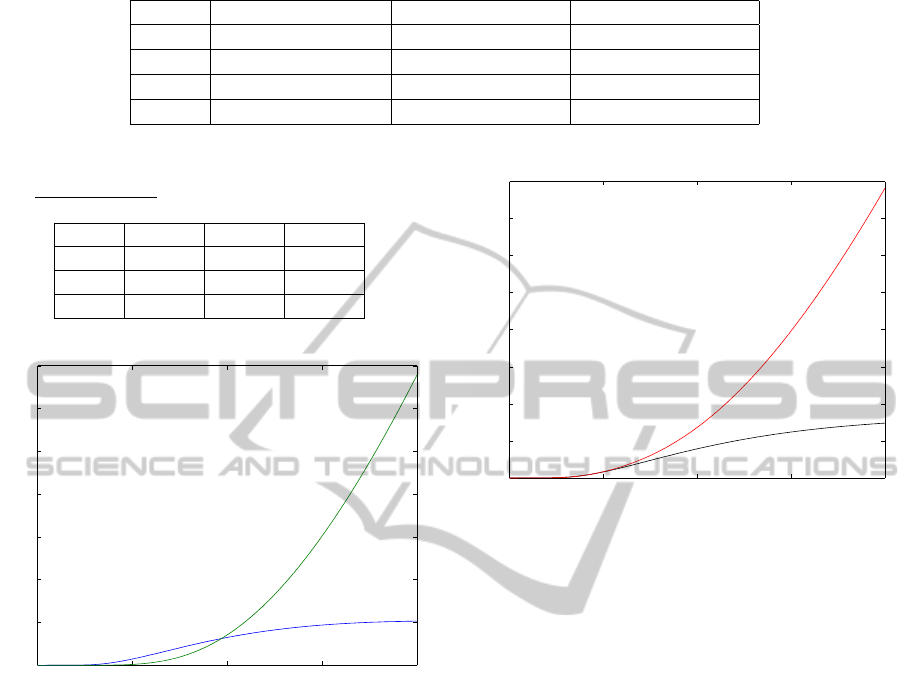
Table 1: Distance calculated in L
1
for solutions at different space steps.
h ku
n
(h) − u
n
(h/2)k
1
kv
n
(h) − v
n
(h/2)k
1
kw
n
(h) − w
n
(h/2)k
1
0.02 2.8810 · 10
−4
0.0013 0.0352
0.01 8.8866 · 10
−5
3.8236 · 10
−4
0.0393
0.005 4.3167 · 10
−5
2.0382 · 10
−5
0.0412
0.0025 1.9924 · 10
−5
1.0474 · 10
−4
1.0611 · 10
−4
Table 2: Numerical order of accuracy, defined by γ
f
=
log
2
k f
n
(h)− f
n
(h/2)k
1
k f
n
(h/2)− f
n
(h/4)k
1
.
h γ
u
γ
v
γ
w
0.02 1.6968 1.7677 0.8399
0.01 1.0418 0.9079 0.9323
0.005 1.1157 0.9611 0.9638
0 0.5 1 1.5 2
0
0.002
0.004
0.006
0.008
0.01
0.012
0.014
time s
Net flux at the end of the MT: cargo (blu) and cargo+dynein (green)
Figure 4: Net flux is calculated at the end of the MT fila-
ment: CARGO (blue) and CARGO+DYNEIN (green).
network and the motor protein dynein to facilitate
their way towards the nucleus. Maybe the most no-
table is the tumor proteins p53, because of its crucial
role in cell life regulation (Roth et al., 2007; Gian-
nakakou et al., 2002). But other proteins, as p38 or
PTHrP are known to be transported by motor proteins
to improve nuclear accumulation (Gong et al., 2010;
Lam et al., 2002).
We performed different numerical experiments to
simulate the presence or not of the microtubule in our
domain. In in vitro experiments ((Roth et al., 2007)),
microtubules dynamics is suppressed by the use of
specific drugs. In this way cargo can not be trans-
ported along the filament. We can easily simulate
these two different states of the cell uncoupling the
third equation of the system.
Our results reproduce qualitatively the behaviour
reported in experiments the by Roth et al. We cal-
culated the net flux of each species at the end of the
0 0.5 1 1.5 2
0
0.002
0.004
0.006
0.008
0.01
0.012
0.014
0.016
time s
Net flux at the end of the MT with and without microtubule activity
Figure 5: The net flux without MT (black) and with MT
(red). As expected, simulations show that the MTs activity
facilitate transport mechanism and makes it more efficient.
microtubule. This is to say we calculated φ
u
(t) =
−d
u
R
L
y
0
∇u · ndy and φ
v
(t) = −d
v
R
L
y
0
∇v · ndy. As we
can see in figure 5 the net flux is higher if the micro-
tubule structure is used for protein trafficking. In the
same way we remark that the flux of the v species is
greater then the flux of the diffusive species u.
In figure 6 we can see the different profiles of u
and v at the final time T. In the case of simple dif-
fusion a natural homogenization process just began.
When microtubule is activated we can see a great dif-
ference in the total concentration profile and remark
the relevance of active transport.
5 CONCLUSIONS
With this simple model we aimed to reproduce a me-
chanical behaviour of signal transport in the cyto-
plasm and to highlight the importance of microtubule
activity. It is still unknown why some proteins use
MTs unlike others. We found a clear difference in the
results (total net flux enhanced thanks to microtubule
based transport) for cargoes that do use this mechan-
ics to move faster towards the nucleus. Our purpose
was not to reproduce data found in literature but to
point out the importance of this second mechanism
BIOINFORMATICS 2011 - International Conference on Bioinformatics Models, Methods and Algorithms
44
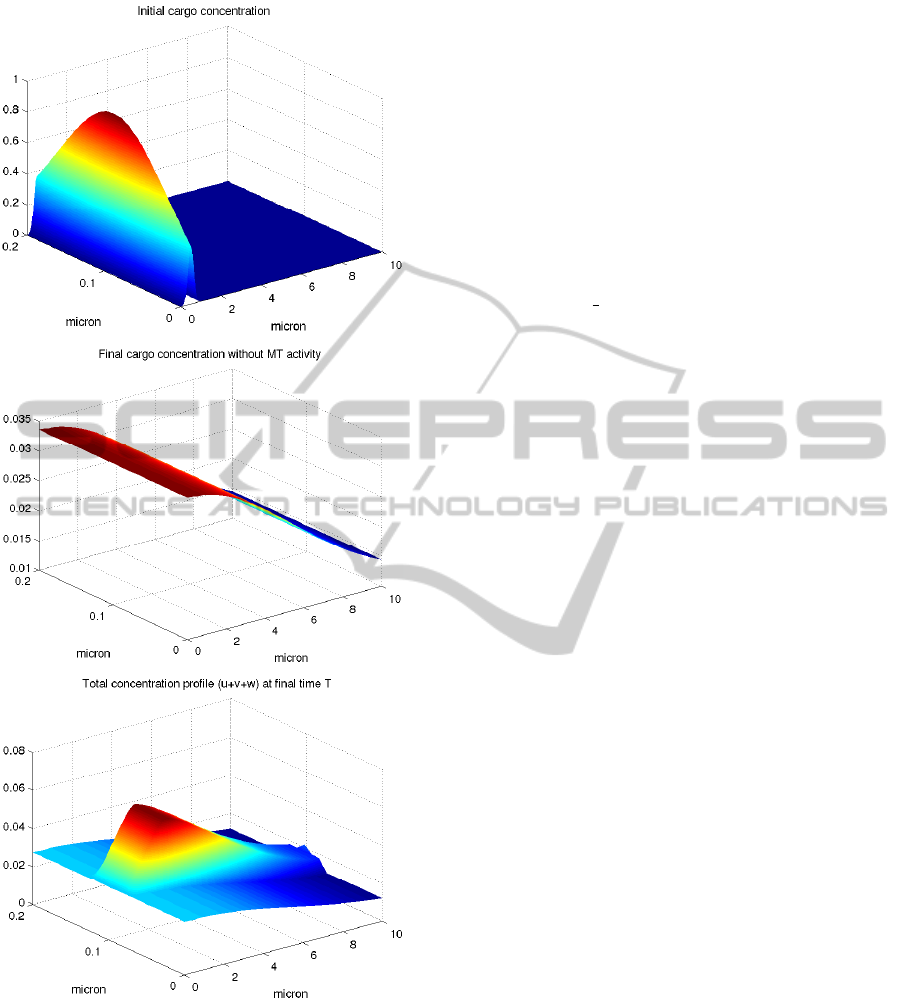
Figure 6: Top: Initial cargo concentration. Middle: final
cargo concentration at T=2, without microtubule support.
Bottom: total concentration profile at T=2 with microtubule
activity.
that has recently been explored as a nuclear protein
trafficking support. Furthermore proteins like p53 or
PTHrP that are tumor suppressors and regulate cell
life have been proved to use the MT network and this
motivate further our study.
Using a PDEs system of equation, with a spatial
representation of the concentration cargo, we could
compare the diffusion mechanism against the advec-
tion one. Our multidimensional approach was a tool
to stress the difference in the two types of transport,
which will be compared in the future to more data in
the literature.
ACKNOWLEDGEMENTS
This work has been supported by CNR Italian Bioin-
formatics Network, MIUR FIRB (RBPR05ZK2Z)
(RBPIN064YAT 003).
REFERENCES
Agutter, P. S., Malone, P. C., and Wheatley, D. N. (1995).
Intracellular transport mechanisms: a critique of dif-
fusion theory. J Theor Biol, 176(2):261–272.
Briani, M., Natalini, R., and Russo, G. (2007). Implicit-
explicit numerical schemes for jump-diffusion pro-
cesses. Calcolo, 44:33–57.
Campbell, E. M. and Hope, T. J. (2003). Role of the cy-
toskeleton in nuclear import. Adv Drug Deliv Rev,
55(6):761–771.
Cangiani, A. and Natalini, R. (2010). A spatial model of
cellular molecular trafficking including active trans-
port along microtubules. J Theor Biol.
Dinh, A.-T., Theofanous, T., and Mitragotri, S. (2007).
Modeling of pattern regulation in melanophores. J
Theor Biol, 244(1):141–153.
Giannakakou, P., Nakano, M., Nicolaou, K. C., O’Brate, A.,
Yu, J., Blagosklonny, M. V., Greber, U. F., and Fojo,
T. (2002). Enhanced microtubule-dependent traffick-
ing and p53 nuclear accumulation by suppression of
microtubule dynamics. Proc Natl Acad Sci U S A,
99(16):10855–10860.
Gong, X., Ming, X., Deng, P., and Jiang, Y. (2010). Mecha-
nisms regulating the nuclear translocation of p38 map
kinase. J Cell Biochem.
Kholodenko, B. N. (2009). Spatially distributed cell sig-
nalling. FEBS Lett, 583(24):4006–4012.
Lam, M. H. C., Thomas, R. J., Loveland, K. L., Schilders,
S., Gu, M., Martin, T. J., Gillespie, M. T., and Jans,
D. A. (2002). Nuclear transport of parathyroid hor-
mone (pth)-related protein is dependent on micro-
tubules. Mol Endocrinol, 16(2):390–401.
Mallik, R., Petrov, D., Lex, S. A., King, S. J., and Gross,
S. P. (2005). Building complexity: an in vitro study
of cytoplasmic dynein with in vivo implications. Curr
Biol, 15(23):2075–2085.
Nan, X., Sims, P. A., Chen, P., and Xie, X. S. (2005). Obser-
vation of individual microtubule motor steps in living
cells with endocytosed quantum dots. J Phys Chem B,
109(51):24220–24224.
A MATHEMATICAL MODEL FOR THE ENHANCED CYTOPLASMIC TRANSPORT - How to Get (Faster) to the
Nucleus
45

N
´
ed
´
elec, F., Surrey, T., and Maggs, A. C. (2001). Dynamic
concentration of motors in microtubule arrays. Phys.
Rev. Lett., 86(14):3192–3195.
Passerini, T., Luca, M. D., Formaggia, L., Quarteroni, A.,
and Veneziani, A. (2009). A 3d/1d geometrical multi-
scale model of cerebral vasculature. Journal of Engi-
neering Mathematics, 64:319–330.
Roe, P. (1981). Approximate riemann solver, parameter
vectors, and difference schemes. J. Comp. Phys.,
43:357–372.
Roth, D. M., Moseley, G. W., Glover, D., Pouton, C. W., and
Jans, D. A. (2007). A microtubule-facilitated nuclear
import pathway for cancer regulatory proteins. Traffic,
8(6):673–686.
Salman, H., Abu-Arish, A., Oliel, S., Loyter, A., Klafter, J.,
Granek, R., and Elbaum, M. (2005). Nuclear localiza-
tion signal peptides induce molecular delivery along
microtubules. Biophys J, 89(3):2134–2145.
Smith, D. A. and Simmons, R. M. (2001). Models of motor-
assisted transport of intracellular particles. Biophys J,
80(1):45–68.
Sweby, P. K. (1984). High resolution schemes using flux
limiters for hyperbolic conservation laws. SIAM J.
Numer. Anal., 21(5):995–1011.
Sweeby, P. (1984). High resolution schemes using flux-
limiters for hyperbolic conservation laws. SIAM J.
Num. Anal., 21:995–1011.
Wagstaff, K. M. and Jans, D. A. (2009). Importins and
beyond: non-conventional nuclear transport mecha-
nisms. Traffic, 10(9):1188–1198.
BIOINFORMATICS 2011 - International Conference on Bioinformatics Models, Methods and Algorithms
46
