
A VIBRATION-BASED ENERGY HARVESTING SYSTEM FOR
IMPLANTABLE BIOMEDICAL TELEMETRY SYSTEMS
Nuno Silva, Paulo Santos
UTAD University, Vila Real, Portugal
Raul Morais
CITAB/UTAD, UTAD University, Quinta de Prados, Vila Real, Portugal
Clara Frias
Department of Mechanical Engineering, Faculdade de Engenharia do Porto, Porto, Portugal
Jorge Ferreira, António Ramos, José A. Simões
Department of Mechanical Engineering, Universidade de Aveiro, Aveiro, Portugal
Manuel J. C. S. Reis
Instituto de Engenharia Electrónica e Telemática de Aveiro/UTAD,Vila Real, Portugal
Keywords: Energy harvesting, Hip prosthesis, Biomedical implant, Telemetry.
Abstract: Using the new trend of energy harvesting, an envisioned electromagnetic power transducer that uses human
gait to produce electrical energy is presented as a solution to energize biomedical devices. Regardless of the
walking speed, starting at 0.7 Hz, it is possible to store a total energy of 2.2 mJ, using two 1000 µF
capacitors as energy storage elements. Afterwards, this energy becomes available to the telemetric system
through an efficient power management module. Since the end application, an implantable biomedical
telemetric system, needs a total of 360 µJ to operate, the here presented power transducer is well suited for
implant power needs.
1 INTRODUCTION
In order to extend the lifetime of an implant, a
completely autonomous power source should be
used. Nowadays, batteries and electromagnetic
induction are the best alternatives, yet they come
with some issues to address. Batteries do not last
long and in the case of rechargeable batteries a
solution to recharge them must be found.
Electromagnetic induction solves those drawbacks,
but the unaesthetic external apparatus can be
uncomfortable and easily broken if its extended use
is required.
Taking a step forward it is presented an
electromagnetic transducer capable of sufficing
power needs of a smart hip telemetry system. With
virtually infinite available energy it is possible to
extend the lifetime of the implant and solve many, if
not all, the aforementioned issues.
This paper presents a telemetric system as the
end application for an electromagnetic vibration-
based energy harvesting power transducer.
Afterwards, a power budget for the intended
telemetric system is defined in order to give an
overview of its power needs. Later, a theoretical
study on this type of transducers is conducted as a
background to the development of a fully functional
329
Silva N., Santos P., Morais R., Frias C., Ferreira J., Ramos A., A. Simões J. and J. C. S. Reis M..
A VIBRATION-BASED ENERGY HARVESTING SYSTEM FOR IMPLANTABLE BIOMEDICAL TELEMETRY SYSTEMS.
DOI: 10.5220/0003134103290332
In Proceedings of the International Conference on Biomedical Electronics and Devices (BIODEVICES-2011), pages 329-332
ISBN: 978-989-8425-37-9
Copyright
c
2011 SCITEPRESS (Science and Technology Publications, Lda.)
generator prototype. Finally an energy storage sub-
system and respective power supply circuit are
presented as solutions for efficient power storage
and usage, respectively.
2 TELEMETRY SYSTEM
Hip prosthesis loosening is one of the main issues
affecting patients who undergo a hip arthroplasty
(Puers et al., 2000). In order to early detect this
loosening, an instrumented and telemeterized
prosthesis is being developed (Morais et al., 2009).
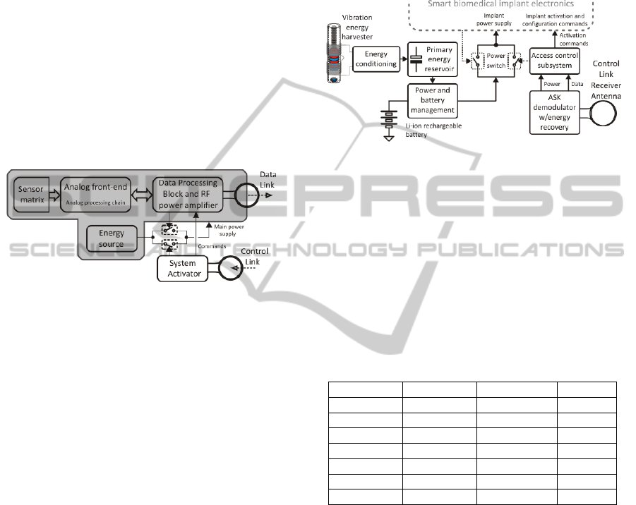
The system comprises a group of piezoelectric
(PZT) transducers, signal conditioning circuitry, data
processing block and a RF transmitter, (Fig. 1).
Figure 1: Telemetry system block diagram (Morais et al.,
2009).
At the beginning, the entire system is in a
shutdown mode in order to preserve energy. After
activation, upon an external command, the system
becomes energized by connecting the main power
supply. After system start-up, sensor data is acquired
by using precision peak detectors. The resulting low-
frequency signals are then converted using 2
nd
-order
Delta-Sigma analog-to-digital converters, processed
by a low-power microcontroller and transmitted to a
base station, located at the patient belt, through a
very low-power RF transmitter. When this process is
finished the entire system is deactivated returning to
the shutdown mode.
2.1 Energy Harvesting and System
Remote Activation
In order to reach an optimized energy management,
the telemetric system is kept in a completely
shutdown mode, being activated when needed or
when energy becomes available through the power
transducer.
As soon as vibrations are present, the transducer
converts those vibrations into electrical energy. This
energy is then stored in a primary energy reservoir
for later use. Even though a Li-ion medical grade
rechargeable battery is currently the primary energy
source, the ultimate goal is to use the transducer as
the main and possibly sole power supply.
Meanwhile transducer stored energy may be used as
a complementary energy source or, for long periods
of telemetric system shutdown mode, it may be used
to recharge the battery, (Fig. 2).
Figure 2: System overview with special focus on the
energy harvester and system activation modules.
2.2 Energy Consumption Profile
In order to determine if the power transducer is
capable of solely powering the telemetric system,
the first step to take is to define its power budget.
Table 1 resumes the power budget of the
microelectronics version of the telemetric system
taking into account its aforementioned sequence of
events and macro device evaluation.
Table 1: Estimated telemetric system energy needs.
Event Power Time Energy
Start-up 660 µW 10 ms 6.60 µJ
Sig. cond. 2.6 µW 5 s 13.20 µJ
Conversion 64.3 µW 267 ms 17.18 µJ
Ctrl & P. 680 µW 277,4 ms 188.6 µJ
RF TX 13.2 mW 10.41 ms 137.4 µJ
Total 0 5564.8 ms 363 µJ
Shutdown 0 294.4 s 0
The sequence of events takes place in
approximately 5.6 seconds and it may completely
drain the stored energy. As explained later, a
shutdown period of 294 seconds was considered a
good compromise in order to provide enough time to
recharge the storage elements. If subsequent data
cycles are needed they will happen each 300
seconds. For a period of 300 seconds it is expected a
total energy consumption of about 363 µJ with an
average power of 1.21 µW (363 µJ/300).
3 PROTOTYPE DEVELOPMENT
In this section a prototype of an electromagnetic
BIODEVICES 2011 - International Conference on Biomedical Electronics and Devices
330
generator is presented.
3.1 Theory Background
Regarding power generation using human
movements, Velocity-Damped Resonant Generators
(VDRGs) are the best approach as suggested by von
Buren et al. (2006) and Yun et al. (2008).
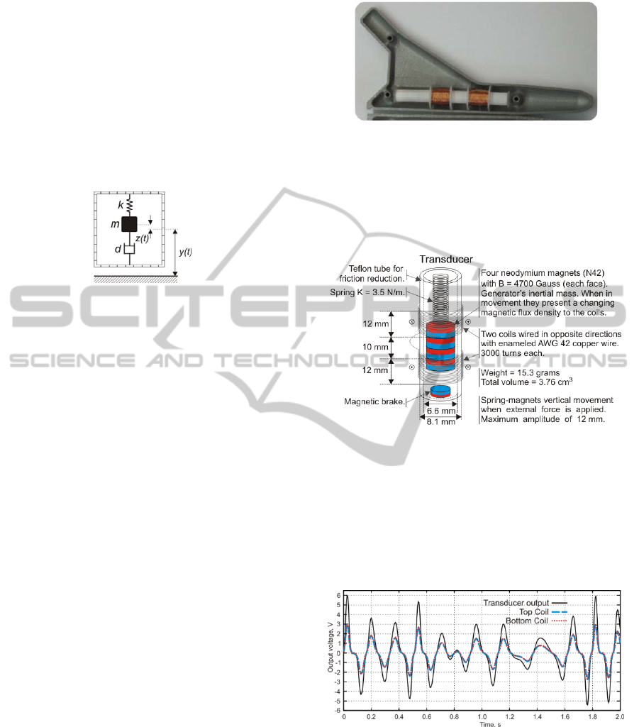
These generators, also known as inertial
generators, can be represented using a basic
mechanical structure, as presented in Fig. 3.
Figure 3: Basic mechanical representation of an inertial
generator.
Independently of the transducer mechanism, used
to build such generators, electrostatic, piezoelectric
or electromagnetic, average generated power can be
determined using (1).
P = m
ξ
e
Y
0
2
(ω / ω
n
)
3
ω
3
/
(
[ 1 − (ω /
ω
n
)
2
]
2
+ [2 ξ (ω / ω
n
)
]
2
)
(1)
This expression was the end result of a frequency
domain analysis presented by Li et al. (2000). Here,
Y
0
is the external excitation amplitude, ω is the
system’s excitation frequency, ω
n
is the system’s
natural frequency, m is the inertial mass and ξ = ξ
e
+
ξ
m
is the overall damping factor, where ξ
e
and ξ
m
are
the electrical and mechanical damping factors.
Since damping factors depend on the transducer
mechanism, and the proposed transducer is of the
electromagnetic type, ξ
e
= (B l)
2
/ (2 R
L
m ω
n
) and
ξ
m
= d / (2 m ω
n
), where B is the magnetic flux
density, l is the coil’s length, d is the mechanical
damping ratio and R
L
the electrical load presented at
the generator output.
As discussed by Li et al. (2000), there is a power
and voltage maximization at resonance (ω = ω
n
),
resulting in P = mξ
e
Y
0
2
ω
n
3
/ 4ξ
2
andV = BlY
0
ω
n
/2ξ.
3.2 The Generator
Taking into account the available volume inside a
hip prosthesis model (Simões et al., 2000), serving
as a base model for this project, a specific generator
prototype was manufactured, (Fig. 4).
Figure 4: Electromagnetic power generator inserted inside
a hip prosthesis model.
Fig. 5 clearly presents generator composition
revealing the details of its operation. Considering
Lenz’s law, coils are expected to produce signals
that are equivalent in amplitude and phase.
Figure 5: 3D representation of the generator.
For testing purposes the generator is attached to
the hip location of a group of human subjects, for
actual human walking generator external excitation.
Fig. 6 presents the synchronism test, where can be
seen the expected doubled voltage amplitude at
generator’s output plugs, when coils are series
connected.
Figure 6: Transducer coils working in synchronism.
3.3 Energy Storage
In order to optimize harvested energy storage and to
accelerate capacitors charging, a series rectifier
configuration was used, (Fig. 7).
In order to prevent early capacitors’ energy usage, a
low power start-up sub-module is used.
A VIBRATION-BASED ENERGY HARVESTING SYSTEM FOR IMPLANTABLE BIOMEDICAL TELEMETRY
SYSTEMS
331
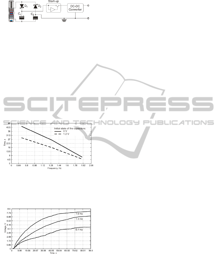
Figure 7: Energy storage and power supply circuit.
Only when capacitors’ combined voltage reaches
a usable level (V
H
= 3.2 V) this voltage is connected
to the DC-DC converter and subsequently to the
telemetric system. Once capacitors’ combined
voltage drops to a considered minimum value (V
L
=
1.2 V), the start-up sub-module disconnects
generator’s load.
Considering that each capacitor will be charged
at half this values, using E = C/2 [(V
H
)
2
– (V
L
)
2
]
with C = C
1
= C
2
= 1000 µF an energy of 1.1 mJ is
stored in each capacitor, leaving us with a total 2.2
mJ of usable energy.
Fig. 8 clearly shows that, for a worst case
scenario, more than 40 seconds are needed to
recharge the capacitors.
Figure 8: Average time taken to recharge storage
capacitors, for a range of gait speeds.
Fig. 9 presents actual capacitors’ voltage
evolution, over time, for a set of pace frequencies,
covering the full range of tested walking speeds.
Figure 9: Capacitors’ voltage evolution over time.
Considering that patients will probably not walk
at a steady pace and may even stop to rest, if
repeated data acquisition cycles are needed, 300
seconds between cycles is a secure compromise.
Taking all this preliminary results into account, it
is considered that the proposed electromagnetic
transducer is more than capable of solely powering
the envisioned microelectronic telemetric system.
4 CONCLUSIONS
Since the end application is located inside a hip
prosthesis, where vibrations are expected with
abundance, the proposed electromagnetic generator
follows the vibration to electrical energy conversion.
As demonstrated, using mechanical vibrations
produced by the human gait it is possible to harvest
enough energy, with this generator, to suffice power
needs of the aforementioned telemetric system.
As future work it is intended to further maximize
useful energy storage. This will allow extended
telemetric system’s working cycle and upgrade
system functionalities.
ACKNOWLEDGEMENTS
The authors would like to acknowledge the
Portuguese Foundation of Science and Technology
(FCT) that partially sponsors this research work
through the project reference PTDC/EME-
PME/105465/2008.
REFERENCES
Puers, R., Catrysse, M., Vandevoorde, G., Collier, R. J.,
Louridas, E., Burny, F., Moulart, M., 2000, Sensors
and Actuators A: Physical, 85: 42 – 47.
Morais, R., Frias, C., Silva, N., Azevedo, J., Serôdio, C.,
Silva, P. M., Ferreira, J., Simões, J., Reis, M.C., 2009,
Sensors and Actuators A: Physical, 156: 229 – 236.
Von Buren, T., Mitcheson, P. D., Green, T. C., Yeatman,
E. M., Holmes, A.S., Troster,G, 2006, IEEE Sensors
Journal, 6:28 – 38.
Yun, J., Patel, S., Reynolds, M., Abows, G., 2008,
UbiComp ’08 , 74 – 83.
Li, W. J., Wen, Z., Wong, P. K., Chan, G. M. H, Leong, P.
H. W., 2000, World Automation Congress, ISORA.
Simões, J., Marques, A., Jeronimidis, G., 2000,
Composites Science and Technology, 60 (4): 559 –
567.
BIODEVICES 2011 - International Conference on Biomedical Electronics and Devices
332
