
BIOELECTRIC ACTIVITY RECORDING BASED ON A SINGLE
ELECTRODE FOR USE ON WEARABLE DEVICES
M. S. Fernandes, C. M. Pereira, J. H. Correia and P. M. Mendes
Algotimi Center, University of Minho, Campus de Gualtar, 4710-057 Braga, Portugal
Keywords: Bioelectric signals, Wearable systems, Biotelemetry, Contactless measurement.
Abstract: Wearable devices are used to unobtrusively record several physiological signals. Bioelectric signals are one
of the most important variables monitored. Despite the available techniques, including capacitive coupling,
it is still lacking a contactless solution that can be integrated into wearable devices. We propose a new
approach where an instrumentation amplifier is directly driven by a bioelectric signal. In this way, the
voltage drop on the capacitive electrodes is avoided. In this paper we show the proof of concept, and results
are presented to show how to record an Electrocardiogram (ECG) using this new approach. Measurements
were made using a high-impedance instrumentation amplifier. Results have shown that our approach is
viable for bioelectric signal detection using contactless methods.
1 INTRODUCTION
Advances in electronic, textile and information
technologies have contributed to the design of
wearable monitoring systems, aimed to provide
continuous, unobtrusive and remote monitoring of
physiological signals. An important contribute is
made by novel technologies for detecting bioelectric
signals. Not every sensor can be used in a wearable
context and a set of attributes must be taken into
account. These include physical attributes such as
size and weight, as well as easy placement and an
unobtrusive aspect. In addition, wearable sensors
must ideally produce an electrical output in order to
be digitally processed. Properties such as durability,
reliability and low power consumption are also
demanded (Constantine and Fotiadis, 2005)
(Winters and Wang, 2003). Acquisition devices are
based on contact or contactless measurements.
Focusing on the first type, two main options arise:
dry or wet (require gel) electrodes. There are some
semi-invasive solutions available, where the
electrodes are based on micro spikes that go trough
the skin (Ng et al., 2009). On the other hand, with
contactless measurements, the available solutions
consist in the use of a capacitive or inductive
coupling, and also the use of electro-active materials
(e.g. electro-optic material). However, since they use
electrodes to drive the signal, a significant potential
drop occurs, causing difficulties in the detection of
smaller signals such as brain electric activity.
The focus of this work consists in proposing an
approach towards contactless detection of bioelectric
signals. In this paper we will demonstrate the
concept of the non-contact acquisition of bioelectric
signals, using the bioelectric field to directly drive
an instrumentation amplifier, instead of the
conventional use of big capacitive electrodes. This
will significantly benefit the design of contactless
bioelectric sensors particularly for wearable
applications. The experimental setup used to the
proof of concept of our approach will be described
as well as the results obtained.
2 CONTACTLESS
MEASUREMENT
The need for physical contact has for long been a
problem when envisioning a wearable monitoring
application. Ideally, a biopotential recording system
should draw no real charge current from the body,
allowing to perform non-contact measurements of
biopotentials. However, the present solutions imply
a voltage drop across the electrode, either wet, dry or
capacitive, limiting the sensitivity and ability to
provide efficient contactless measurements. When
looking into the wearable matter, the standard
130
Fernandes M., Pereira C., Correia J. and Mendes P..
BIOELECTRIC ACTIVITY RECORDING BASED ON A SINGLE ELECTRODE FOR USE ON WEARABLE DEVICES.
DOI: 10.5220/0003129101300134
In Proceedings of the International Conference on Biomedical Electronics and Devices (BIODEVICES-2011), pages 130-134
ISBN: 978-989-8425-37-9
Copyright
c
2011 SCITEPRESS (Science and Technology Publications, Lda.)

solutions show two main problems: they are difficult
to integrate with the vests and uncomfortable to
wear. A new generation of sensors is required in
order to surpass the limitations of the present
solutions.
We propose a new approach for contactless
detection of biopotentials that avoids the voltage
drop by directly driving an instrumentation amplifier
with a bioelectric signal. The input impedance of the
instrumentation amplifier should be as high as
possible in order to allow the remote detection of
biopotentials. Moreover, input technologies based on
Complementary Metal–Oxide–Semiconductor
(CMOS) and Field-Effect Transistors (FET) should
be used since they are driven by voltage instead of
current. In our approach there’s only one contact
with the subject skin, responsible for establishing a
reference signal – reference electrode. In this way,
bioelectric signals will be simultaneously measured
without any contact at the recording locations,
sharing the same reference.
We are particularly envisioning the application of
this approach in brain biopotential wearable systems.
The existent solutions are not suitable for use in
fully wearable devices. With our approach, we hope
to contribute to the design of appropriate wearable
sensors for further applications in relevant areas
such as Brain-Computer Interface (BCI). Figure 1
shows an example of application of our contactless
approach in Electroencephalogram (EEG) wearable
recordings, where the sensor would be placed close
to the scalp. One of the inputs is connected to the
contact reference electrode. The other is floating in
order to drive the instrumentation amplifier with the
bioelectric signal.
Figure 1: Contactless sensor for biopotential acquisition.
Dashed lines are used to indicate that the sensor may be
placed in several recording locations.
The standard setups use the ear lobes as a
reference signal, since there’s minimal influence of
temporal lobe or muscle electrical activity.
However, from a user perspective, it would be
preferable to place the reference in a more discreet
place, since the main objective of wearable systems
consists in providing ubiquitous monitoring in daily
life activities. Therefore, we propose to place the
reference electrode on the back neck, establishing
the only contact with the skin. The recording sensors
are placed near the target locations, without any kind
of contact with the scalp.
3 BIOELECTRIC SIGNALS
3.1 Signal Characterization
Bioelectric signals are recorded as voltages,
potentials and electric field strengths, at very low
levels, with high source impedances and overlaid
interference signals and noise. They can be
classified according to the type of cells and tissue
they are originated from. Table 1 lists the most
relevant biopotentials along with its properties
(Webster, 1988).
Table 1: Properties of Biopotentials (ECG –
Electrocardiogram; EOG – Electrooculogram; EMG –
Electromyogram).
Biopotential
Tissue Amplitude
Frequency
ECG Heart 1-5 mV 0.05-100 Hz
EEG Brain
10-200 μV
0.5-40 Hz
EOG Retina 0.01-0.1 mV dc-10 Hz
EMG Muscles 1-10 mV 20-200 Hz
It’s important to note that due to several
constrains resultant from travel and propagation (e.g.
tissue resistivity), detected properties such as
amplitude and shape will be very distinct from those
detected inside the specific tissue that originates the
bioelectric event.
3.2 Standard Readout
The three essential components required to measure
a bioelectric signal are: bioelectrodes,
instrumentation amplifiers and filtering components
(Neuman, 1998). On the process of sensing a
biopotential, it is required to provide some interface
between the body and the measuring device. This
interface is carried out by bioelectrodes that convert
the ionic current within the body into electronic
current in metal connecting leads (Neuman, 1998).
Bioelectrodes should have low impedance.
Otherwise the currents driving the subsequent
amplifier will lead to a biopotential drop, leading to
BIOELECTRIC ACTIVITY RECORDING BASED ON A SINGLE ELECTRODE FOR USE ON WEARABLE
DEVICES
131

more difficult readouts. Three types of interface
between the electrode and the skin can be applied:
wet, dry/insulated and capacitive coupled. The first
one makes use of an electrolytic gel that helps to
promote the reduction of the contact impedance,
minimizing the risk of signal loss. This carries time-
consuming and complex procedures. The most
commonly used wet bioelectrode is the gel type
silver/silver chloride (Ag/AgCl), which can be found
both in reusable or disposable form. Dry and
insulated electrodes eliminate the need for an
electrolytic paste. The first type consist of a
biocompatible metal in direct contact with the skin,
being the coupling between them made by the user’s
sweat produced after it’s placement. On the other
hand, insulated electrodes are based on a dielectric
surface layer between the metal or semiconductor
and the skin. In this case, the bioelectric signal is
capacitively coupled between the skin and electrode,
without requiring electrical contact with the skin.
Some examples of dry/insulated electrodes and their
application can be found in (Baek et al., 2008; Ryu
et al., 2005). The third type of interface requires no
physical contact with the skin and it’s based on
capacitive pick-up electrodes. Basically, the
biopotential is obtained by capacitive coupling
between the body and the electrode, working both as
plates of a capacitor (Harland et al., 2002).
Bioelectric signals need to be amplified in order
to make them compatible with a variety of devices
such as A/D converters or display equipments. The
instrumentation amplifier is commonly used to
record biopotentials since it fulfils the basic
requirements for biopotential amplifiers, being
designed to have extremely large input impedance
and a small bias current. It works as a differential
amplifier, by applying high gain amplification
between signals at the positive and negative inputs.
Since the input signal of the amplifier consists of the
desired bioelectric signal and unwanted components
(e.g. power line interference signals, noise, etc.), it is
crucial to include a filtering stage. Generally, a
notch filter centered at 50 Hz (60 Hz in USA), and a
bandpass filter are used to remove these unwanted
signal components, that sometimes have higher
amplitudes than the desired bioelectric signal.
4 MEASUREMENTS
Measurements were carried in order to demonstrate
the concept of biopotential contactless recording.
The proof of concept consists into two stages: the
first experiment uses a conventional instrumentation
amplifier with subsequent filtering and amplification
stages; then, the resultant filtered and amplified
ECG is directly and contactless driven into a FET-
input instrumentation amplifier.
4.1 Experimental Setup
The modules used to validate our approach for
contactless detection of bioelectric signals include:
instrumentation amplifiers, notch filters, band-pass
filters and voltage amplifiers. The type of amplifiers
used, instrumentation amplifiers, need to fulfil a
particular set of requirements in order to provide
selective amplification to the biopotential, rejecting
the superimposed noise and interference
components:
- Have high input impedance (at least 10 MΩ)
and electrical isolation in order to inhibit
interference or distortion of the recorded signals.
- High CMRR (>80 dB according to (Neuman,
1998)) in order to separate as much as possible the
relevant signal from noise and interferences;
- Supply enough gain within its bandwidth in
order to reach an output level compatible with the
remaining system.
- Have low output impedance and supply the
amount of current necessary to the load.
- Provide protection to the patient from any
hazard of electrical shock.
Figure 2 shows the first module used in the
carried experiments.
Figure 2: First module comprising a conventional
acquisition circuit for biopotentials. LA corresponds to
Left Arm, and RA to right arm.
At this stage, an electrode was placed on each
arm, according to Lead I of Einthoven’s triangle,
resulting in a differential recording. The electrodes
were connected to both inputs of a precision
instrumentation amplifier (INA129, Texas
Instruments) with an input capacitance of 2 pF
(10
10
Ω) and a CMRR of 125 dB. The gain of the
amplifier was set to 155, by placing an RG of 320 Ω.
Since electrical circuits are usually interfered by ac
power lines, a notch filter was used to remove this
50 Hz interference, with an attenuation of 33.9 dB.
BIODEVICES 2011 - International Conference on Biomedical Electronics and Devices
132
To remove other unwanted signal components such
as other bioelectric signals or movement artefacts,
we designed a bandpass filter with unity gain and a
bandwidth set according to the frequency
components of interest (see Table 1). After the
filtering components, the ECG signal drives an
amplification stage with a gain of 100. The total gain
of this module is 255.
The second stage implements the contactless
module and consists of directly driving a FET-input
instrumentation amplifier, by placing an isolated
wire loaded with the resultant bioelectric signal from
the first stage. Figure 3 depicts the contactless
module of the experiment.
Figure 3: Contactless module comprising a conventional
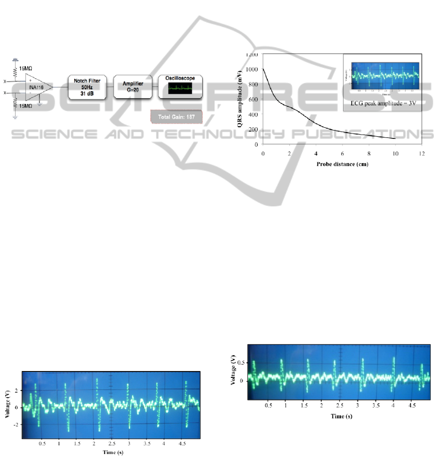
acquisition circuit for biopotentials (x = No connection).
The ECG signal is used to directly drive the INA116 with
an isolated probe.
The bioelectric signal was directly and
contactless coupled by placing an isolated wire 1 cm
above a FET-input instrumentation amplifier
(INA116, Texas Instruments) with an input
impedance of 0.2 pF (10
15
Ω) and a CMRR of 94 dB.
The signal was further amplified with a gain of 20.
4.2 Results
Experiments were carried out in order to test the
recording of bioelectric signals with no contact with
the skin, neither electrical nor mechanical. Fig. 4
shows the bioelectric signals recorded at the end of
the first stage.
A first view of Fig. 4 allows to point some of ECG
components, including the P wave, QRS complex
Figure 4: ECG signal obtained at the end of the first circuit
module. The average amplitude of the signal is 3 V.
and the T-wave. Each one corresponds to a specific
electrical event that occurs during heart activity, for
instance the QRS complex occurs as the ventricles
depolarize. The average signal amplitudes reached a
value of 3 V, after a 255 total gain.
This signal is further used for contactless driving
the INA116, using an isolated probe placed at
different distances. To test the distance influence, we
varied the distance between the probe and the
instrumentation amplifier. Initially, the probe was
placed in external contact with the INA116, and then
went up to a 10cm distance. Figure 5 shows the ECG
signal strength obtained for the different distances
used.
Figure 5: QRS peak amplitude versus distance between the
instrumentation amplifier and the probe. The values
represent peak-to-peak amplitudes. The inset represents
the signal which is directly coupled from the probe to the
INA116.
These results demonstrate a decrease in signal
strength, as the distance between the INA116 and
the probe increases. Above 10 cm, the signal
becomes smaller than the noise components, causing
difficulties to isolate the relevant bioelectric signal
from the noise and interference. In figure 6 we show
an ECG recorded at a distance of 1cm from the
INA116.
Figure 6: ECG signal recorded at a distance of 1cm from
the INA116. An isolated probe was used to carry the
signal from the first module. The average amplitude is 600
mV.
BIOELECTRIC ACTIVITY RECORDING BASED ON A SINGLE ELECTRODE FOR USE ON WEARABLE
DEVICES
133

As shown in fig. 6, we can easily identify the
QRS complex, and part of the T-wave. The periodic
pattern displayed is similar to the conventional ECG
detected in the first module (Fig. 4). In terms of
amplitudes, the signal reaches a maximum of 600
mV. When envisioning wearable devices, ensuring a
good sensor performance at a distance of 1 cm is
desirable.
5 CONCLUSIONS
The developments described here open a new
approach to non-contact recording of bioelectric
signals, with promising applications in wearable
systems. A method for testing non-contact
acquisition of biopotentials by directly driving an
instrumentation amplifier with a previously
amplified and filtered ECG signal was proposed.
Measurements were made using a high-impedance
FET-input amplifier (INA116) and an isolated
probe, varying the distances between them. We
tested the performance of this approach in these
conditions, and results have shown the possibility of
successfully contactless acquire a readable ECG
until 10 cm of distance from the source, suggesting
that these approach could be used in bioelectric
wearable sensors.
Future work is needed towards the improvement
of sensitivity and noise reduction. This can be
achieved by increasing the input impedance and the
CMRR. The first one will result in smaller
attenuation of the electrophysiological signal. A
higher CMRR improves a better separation of the
relevant signal from noise and interferences. The
gain of the system can be easily set to higher values
by changing the feedback resistor of the amplifier.
ACKNOWLEDGEMENTS
We would like to acknowledge the Center
Algoritmi, the Portuguese Foundation for Science
and Technology (Grant SFRH/BD/42705/2007) and
the MIT Portugal Program, for supporting this work.
REFERENCES
Baek, J. Y., An, J. H., Choi, J. M., Park, K. S., and Lee, S.
H. (2008). Flexible polymeric dry electrodes for the
long-term monitoring of ECG. Sensors and Actuators
A, 143 (2), 423-429.
Constantine, G. and Fotiadis, D. I. (2005). Wearable
Devices in Healthcare. In Silverman, B. G., Jain, A.,
Ichalkaranje, A. and Jain, L. C. (Eds.), Intelligent
Paradigms for Healthcare Enterprises (cap.8, pp. 237-
264). Berlin, Germany: Springer Berlin.
Harland, C. J., Clark, T. D. and Prance, R. J. (2002).
Electric potential probes—new directions in the
remote sensing of the human body. Measurement
Science and Technology, 13 (2), 163-169.
Neuman, M. R. (1998). Biopotential Electrodes. In
Webster, J. G. (Ed.), Medical Instrumentation:
application and design, (cap. 5, pp. 183-232). New
York, USA: John Wiley & Sons.
Ng, W. C., Seet, H. L., Lee, K. S., Ning, N., Tai, W. X.,
Sutedja, M., Fuh, J. Y. H. and Li, X. P. (2009). Micro-
spike EEG electrode and the vacuum-casting
technology for mass production. Journal of Materials
Processing Technology, 209 (9), 4434-4438.
Ryu, C. Y., Nam, S. H. and Kim, S. (2005). Conductive
rubber electrode for wearable health monitoring.
Conference Proceedings - IEEE Engineering in
Medicine and Biology Society, 4, 3479-81.
Webster, J. G. (1988). Encyclopedia of Medical Devices
and Instrumentation (2
nd
ed.), New York, USA : Jonh
Wiley & Sons.
Winters, J. M. and Wang, Y. (2003). Wearable sensors
and telerehabilitation. IEEE Engineering in Medicine
and Biology Society, 22 (3), 56-65.
BIODEVICES 2011 - International Conference on Biomedical Electronics and Devices
134
