
STATIC BALANCE FOR RESCUE ROBOT NAVIGATION
Translation Motion Discretization Issue within Random Step Environment
Evgeni Magid and Takashi Tsubouchi
ROBOKEN - Intelligent Robot Laboratory, University of Tsukuba, Tsukuba, Japan
Keywords:
Random step environment, Rescue robot navigation, Teleoperation, Static balance.
Abstract:
The goal of rescue robotics is to extend the capabilities of human rescuers while also increasing their safety.
During the rescue mission mobile robot is deployed on the site and is operated from a safe place by a human.
A decision on the robot’s path selection is very complicated, since the operator cannot see the robot and the
environment. Our goal is to provide a kind of automatic ”pilot system” to propose the operator a good direction
or several options to traverse the environment, taking into account the robot’s static and dynamic properties.
To find a good path we need a special path search algorithm on debris. The real state space of the search
is extremely huge and to decrease the number of search directions we discretize robot’s motion and the state
space before the search. Search algorithm needs a proper definition of node’s neighborhood, which will ensure
smooth exploration of the search tree. In this paper we present our results in estimation of the transition pos-
sibilities between two consecutive states, connected with a translation step, and discuss the problems arising
from the discretization of the state space. Exhaustive simulations were used to structure, analyze and solve the
discretization issue problems and help to remove unsuitable directions of the search from the search tree.
1 INTRODUCTION
A long standing goal of mobile robotics is to allow
robots to work in environments unreachable or too
hazardous to risk human lives. Urban search and res-
cue is one of the most hazardous environments imag-
inable with victims often buried in unreachable loca-
tions. Rescue robotics is the application of robotics
to the search and rescue domain. The goal of res-
cue robotics is to extend the capabilities of human
rescuers while increasing their safety. In particular,
the inside of severe earthquake stricken buildings or
underground area should be investigated in advance
of manned rescue operation in order to avoid risk of
suffering from secondary disaster. During the rescue
mission the mobile robot is deployed on the rescue
site, while the human tele-operator is monitoring the
robot’s activities and giving the orders from a safe
place outside of the site (Figure1). The system con-
sists of a robot control subsystem and a remote oper-
ation station, connected with a wireless LAN.
In this paper we present our current results in esti-
mation of the transition possibilities of a crawler type
vehicle between two consecutive states, connected
with a translation step within Random Step Environ-
ment, which is a simulated debris environment, pro-
posed by NIST (Jacoff et al., 2001). To find a good
path we implement a special path search algorithm on
debris. Because the debris site is dangerous and un-
stable, the main goal of the algorithm is to keep the
robot maximally stable at every step of its path. The
real state space of the search is extremely huge and
to decrease the number of search directions we dis-
cretize robot’s motion and the state space before the
actual search. A search algorithm utilizes a search
tree (Cormen et al., 2001); for our problem dynam-
ically created search tree cannot be explicitly pre-
sented as a skeleton. To present it as a function
F(Args) = Res, where arguments Args are the robot’s
current configuration and the environment and output
Res is a set of accessible within one step configura-
tions, we need a proper definition of function F which
will guide the tree search. We created a theoretical ba-
sis for this function F and confirmed it with exhaus-
tive simulations, removing all unsuitable directions of
the search from the search tree. A new feature of our
research is a path evaluation process, which includes
robot’s postures quality together with the inter posture
transitions quality.
Currently rescue robots are operated manually by
human operators. The remote operator uses only vi-
sual information about the environment, which is usu-
415
Magid E. and Tsubouchi T. (2010).
STATIC BALANCE FOR RESCUE ROBOT NAVIGATION - Translation Motion Discretization Issue within Random Step Environment.
In Proceedings of the 7th International Conference on Informatics in Control, Automation and Robotics, pages 415-422
DOI: 10.5220/0002945404150422
Copyright
c
SciTePress
ally not sufficient to carry out complex tasks because
of the limited visual fields of cameras. In the case of
an on-site operator, which stays inside a crawler-type
rescue vehicle, the human can feel the inclination of
the vehicle and the decision on the traversability of
the path becomes more easy. Unfortunately, the off-
site operator can not use any of those natural biologi-
cal sensors and have to judge on the next move on the
base of the partial available information, taking sub-
jective and time consuming decisions. Many optional
paths from the start to the target position exist and it is
very hard for the operator to choose a good and safe
path. Transferring the function of taking such deci-
sions to a computer will decrease the burden on the
operator. Our final goal is to provide a ”pilot system”
to propose an operator a good direction or several op-
tions to traverse the environment. The operator will
receive a proposal on a good path from the ”pilot sys-
tem” on the computer display by means of GUI and
apply it in a real scenario driving KENAF robot.
Figure 1: (a) Operator. (b) KENAF traversing RSE.
2 THE SYSTEM FRAMEWORK
The National Institute of Standards and Technology
(NIST) has created a set of reference test arenas for
evaluating the performance of mobile autonomous
robots performing urban search and rescue tasks (Ja-
coff et al., 2001). One of the examples, simulating
cluttered environment with debris is a so-called Ran-
dom Step Environment(RSE) or Stepfield, which is
widely used in the RoboCup Rescue competitions and
rescue related research (Sheh et al., 2007). RSEs are
designed to be easily reproduced, and yet behave in
a similar way to real rubble. RSE consists of a final
number of random steps of some minimal size sim-
ulating a heavily damaged environment of the build-
ings after the earthquake(Figure1b).
Our RSE is constructed from wooden block cells
of 85x85mm size and 0, 90, 180 or 270 mm height
each, where 0mm corresponds to the ground level
around the RSE-patch. We assume a simple tractor-
like crawler non-reconfigurable robot, corresponding
to the main body of ”KENAF” robot(Figure2b). The
main body of ”KENAF” consists of two large tracks
with a small gap in between; the main specifications
of ”KENAF” without sensors, front and the back pairs
of arms, used in experiments and by the simulation
”pilot system”, are given in table 1.
(a) (b)
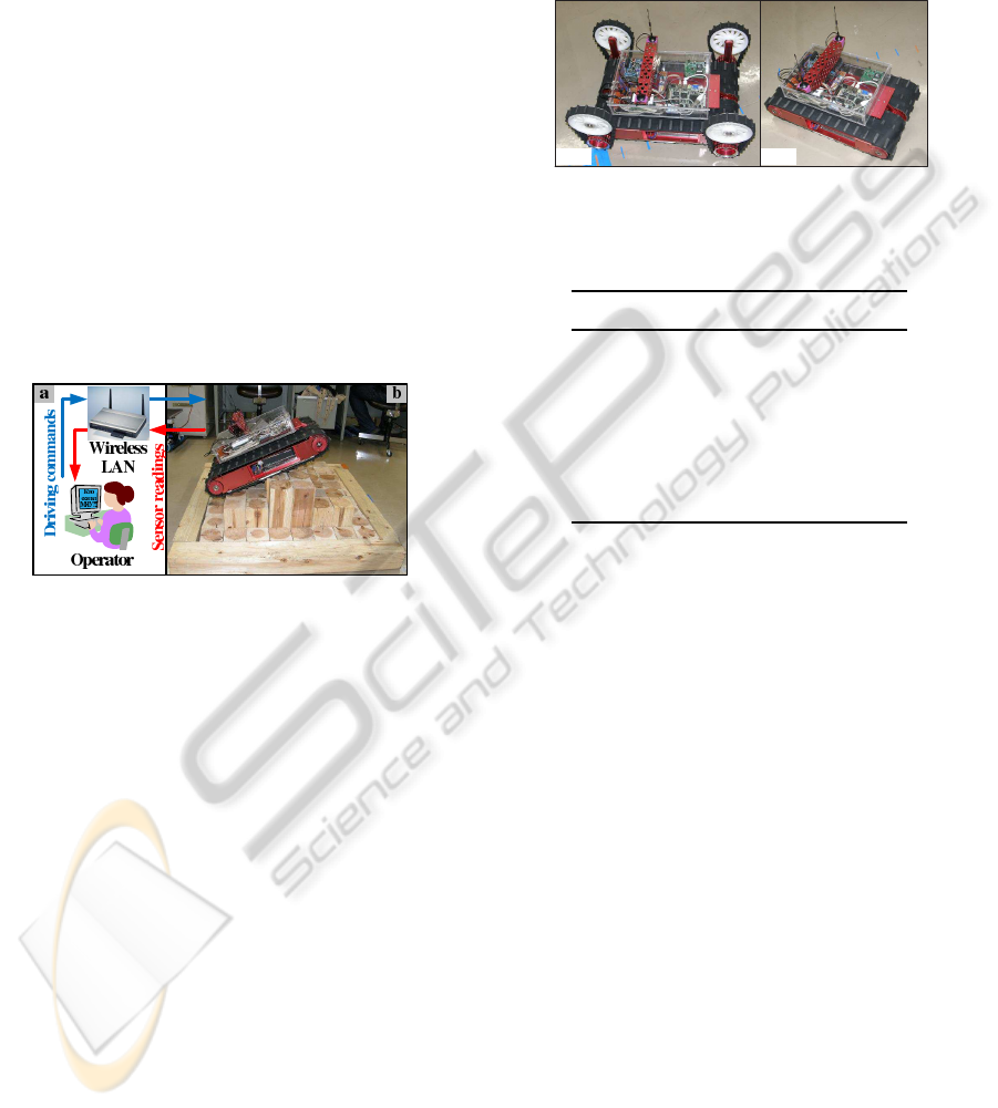
Figure 2: (a)Full KENAF configuration without sensors. (b)
Main body without service arms and sensors.
Table 1: Specifications of ”KENAF” in basic configuration.
Parameter Measurement
Maximal inclination
dynamic 60 deg
static 80 deg
Main body length 584 mm
Main body width 336 mm
Track width 150 mm
Hight 270 mm
Weight 17.8 kg
3 STATIC STABILITY AND
BALANCE ESTIMATION
The most important question which the path search
algorithm should be able to answer is if a specific
robot configuration is possible or not. This includes
not only collisions with the obstacles, but also the ca-
pability of the robot to keep the current configuration.
The robot should be able to stay in the specific con-
figuration without slippering or turning upside-down.
In other words, a safe and reliable motion of an au-
tonomous vehicle requires continuous satisfaction of
static and dynamic constraints (Shoval, 2004). Static
stability is a minimal necessary condition for the gen-
eral vehicle stability. For the static stability satisfac-
tion the robot’s center of mass (CM) must lie above
the support polygon - a polygon with vertices at the
contact points of the robot’s crawlers with RSE.
In (Magid et al., 2008) we presented an algorithm
for static balance posture estimation of the robot’s
posture in a specified configuration. In this section
we give a brief description of the static balance pos-
ture types where we give color names, and add one
new posture type - cyan. From the point of static bal-
ance estimation, we distinguish six posture types:
ICINCO 2010 - 7th International Conference on Informatics in Control, Automation and Robotics
416
(R) Red State. Presents a statically unstable pos-
ture; it results in robot’s turning upside down while
trying to climb to an impossible steepness.
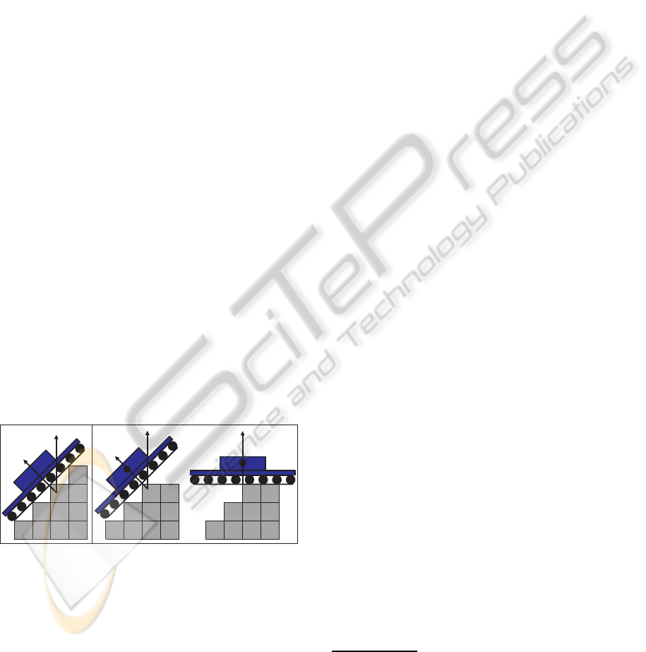
(G) Green State. Stands for a statically stable pos-
ture (Figure3a).
(Y) Yellow State. Is a private case of green state.
Normalized Energy Stability Margin (NESM) (Hirose
et al., 1998) is applied for estimating the quality of the
green state posture. Green state turns into yellow if
the S
NESM
criterion does not exceed a predefined min-
imum established in the process of experiment trials
with KENAF robot.
(O) Orange State. Is something between red and
green states. This posture is possible, but not stable. It
does not result in robot’s turning upside down, but do
not guarantee a single stable posture since there exist
two options and the real one depends on the preceding
posture and moving direction. Figure3b demonstrates
a side view of an orange state with two possible pos-
tures. The orange state is very important, since it af-
fords the robot to lose the balance on purpose, when
for example the robot traverses the barrier. Travers-
ing the barrier includes climbing up and going down
with loosing balance twice on top of the barrier. We
distinguish O
1
and O
2
cases. O
1
is the first part of the
O-posture, before the robot looses its balance. O
2
is
the second part, which occurs after the robot have lost
its initial balance; robot changes its posture discontin-
uously at that point and obtains a balance again in a
different body orientation.
ZL
ZG
CM
ZG, ZL
CM
b
ZL
ZG
a
Figure 3: a) Green state b) Orange state: O
1
(left) and O
2
(right).
(M) Magenta State. Appears when the robot has
to climb up or to slide down the vertical slope of the
environment; it is legal only for translation motion.
(C) Cyan State. The cyan posture is detected be-
tween two successive G/Y/O postures if CM posi-
tion change in Z-coordinate exceeds the predefined
threshold. This jump is detected only after the sec-
ond posture is explored and compared to the first pos-
ture. Cyan posture is legal only for a rotation motion.
1
Further we denote by C-posture a posture which static
balance corresponds to a Cyan type, R-posture - red
type etc.
4 SEARCH SPACE AND SEARCH
TREE
Next important task of the search algorithm is to de-
cide on possible next steps of the robot from a given
current location and orientation. In standard 2D nav-
igation there are 2 types of cells in the state space
”free” and ”obstacle” and all transitions between free
adjacent cells are legal (Latombe, 1991). Our impor-
tant improvement of the existing approach is as fol-
lows. We have ”possible” (stable) and ”impossible”
(unstable) postures with regard to robot’s static sta-
bility; but even in a case of two adjacent ”possible”
postures we check if the transition between them is
legal. To decrease the number of search directions we
discretize robot’s motion and the state space before
the search. Next exhaustive simulations and experi-
ments will remove all unsuitable search directions.
Initially we had chosen 3 levels of search space
discretization for XY-coordinates of the environment:
• DISC2 - each 85x85mm cell of RSE turns into
2x2 cells of the internal robot map with the cell
size of 42.5x42.5mm
• DISC5 - 5x5 cells of 17x17mm size per RSE cell
• DISC10 - 10x10 cells of 8.5x8.5mm size per cell
KENAF supports two types of motion: translation
and rotation. Thus at each node of the search tree the
search algorithm has to open the 3-neighborhood of
the node - go straight or turn left/right - and to proceed
the search in the most promising direction. Immedi-
ately we must cut off from the search tree all impossi-
ble search directions, which are different for rotation
and translation steps. In this paper we present our
results in estimation of the transition possibilities be-
tween two consecutive states, connected with a trans-
lation step.
Translation step is defined as a one cell length
step forward in the direction of robot local frame’s
axis X
L
. Transition between two stable postures is
1
Exhaustive simulations showed that cyan posture exists
for the translational motion only due to the discretization is-
sue: it exists for a big scale of the internal map of DISC2
(as defined in section 4), rarely appears at DISC5 and al-
most disappears at DISC10.
STATIC BALANCE FOR RESCUE ROBOT NAVIGATION - Translation Motion Discretization Issue within Random
Step Environment
417
Experiments
Hypothesis
ExperimentsSimulations
Mobile
Capability
Feeling
Environment
Existance
Feedback
Correlation
Generalization
Basic Logic
Figure 4: Theory, simulations and experiments.
not always possible and to define this condition, we
created a set of theoretical hypotheses, based on our
experimental experience. Exhaustive simulations for
environments existence in MATLAB and experiments
with KENAF robot in RSE gave a valuable feedback
for our theory and finally produced a branch cut-
ting condition for the path search algorithm(Figure4).
Successive transition patterns will be integrated in the
search algorithm as a part of neighbor opening and
branch cutting function F(Args) = Res.
5 DESCRIBING A POSTURE
To characterize robot’s posture qualitatively we use
the coloring of the states. To decide possible transi-
tions between two successive states, we have chosen 6
variables, whose combinations help us to define legal
transitions between the states.
Tx
CM
XL
XL
projection
CM
YL
Ty
XL
YL projection
(a)
(b)
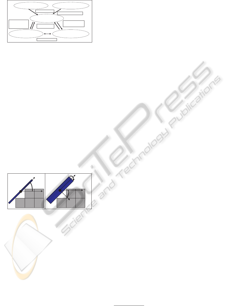
Figure 5: (a) Steepness θ
X
. (b) Moment θ
Y
.
Steepness θ
X
. The angle, showing the steepness of
the environment at a given robot configuration. Angle
between the local axis X
L
and its projection on the
plane of the global axes X
G
, Y
G
(Figure5a).
Moment θ
Y
. The angle, showing the dangerous ro-
tational moment around robot’s X
L
-axis at a given
configuration. Angle between the local axis Y
L
and
its projection on the plane of the global axes X
G
,
Y
G
(Figure5b).
Contact Points Quality (CPQ). Depends on the
angle θ
CPQ
between the robot’s crawlers and the
edges of the RSE cells and affects the robot’s ability
of climbing the obstacles and sliding down safely.
Inclination. Is the sign of the steepness angle θ
X
.
We distinguish three groups of posture sets with re-
spect to this parameter: G
U
inc
is a climbing up the
steps of the environment posture, G
D
inc
is a going
down and G
Z
inc
is a neutral inclination posture.
M-sign. Is the sign of the moment angle θ
Y
. Similar
to inclination, group G
P
MS
contains all postures with
positive M-sign, G
N
MS
with negative and G
Z
MS
with
neutral
2
.
NESM-stability. Shows the probability of the
robot’s turning upside down because of the situation,
when the CM is too close to one of the edges of the
support polygon in the sense of NESM.
Inclination and M-sign are the most important
variables. They signal about discretization problems,
pointing on the missed posture between two succes-
sive postures due to the discretization issue. 4 other
variables are emphasized for the experimental work
and particulary for creating input, which will satisfac-
torily span all possible translation step cases.
6 HYPOTHESES
We conducted a large set of experiments with KENAF
robot in several Random Step Environments. Based
on operation experience and basic logic, we created a
set of rules on the translations (TR) between two suc-
cessive postures. It includes trivial statements, defini-
tions and assumptions:
(TR1) Translation preserves orientation θ.
(TR2) Starting at O
1
posture, we immediately
translate to O
2
as a result of inertia; there is no way to
obtain O
2
posture without previously obtaining O
1
.
(TR3) Z-posture is defined if robot’s body is par-
allel to the ground level: G
Z
inc
T
G
Z
MS
(TR4) The only way to climb up or slide down
a vertical slope of RSE is to apply a sequence of M
postures between two stable postures (start and end
of the M-sequence). M-sequence cannot contain any
non-M posture.
(TR5) C-posture does not exist.
(TR6) M-posture has no real θ
X
, θ
Y
and NESM
parameter data, but only an approximation. Also it
has no own inclination and M-sign data.
(TR7) NESM-stability coefficient is zero for O-
postures.
(TR8) Change of inclination between two pos-
tures can occur only through O-posture and its O
1
or
O
2
is a Z-posture.
2
G
Z
inc
: |θ
X
| ≤ ε; G
Z
MS
: |θ
Y
| ≤ ε; ε=1 degree
ICINCO 2010 - 7th International Conference on Informatics in Control, Automation and Robotics
418

(TR9) Change of M-sign between two postures
can occur only through O-posture.
(TR10) Significant change of steepness θ
X
so
that ∆θ
X
.
= |θ
X
(P
prev
) − θ
X
(P
curr
)| ≥ TX
MAX
without
change in inclination or M-sign between two postures
can occur only through M-posture.
(TR11) If the change between two successive pos-
tures in θ
Y
is ∆θ
Y
≥ TY
MAX
degrees, it can occur only
through O-posture.
(TR12) The possible change between two succes-
sive postures for a uniform translation motion case is
∆θ
X
≤ TX
MIN
and ∆θ
Y
≤ TY
MIN
degrees.
(TR13) Inevitable O-posture (IOP) is obtained
while passing the edge of the RSE-cell. If the posture
(x,y,θ), preceding IOP, becomes (x±δ
x
,y±δ
y
,θ) with
δ
x,y
→ 0, we will again and again obtain this IOP at
the next translation step, i.e. IOP is preserved in the
case of small shift δ in at least one direction.
(TR14) Accidental O-posture (AOP) is obtained
while passing through the corner of the RSE-cell. If
the robot posture (x,y,θ), preceding AOP, would be-
come (x±δ
x
,y±δ
y
,θ) with δ
x,y
→ 0, this AOP will not
be obtained at the next translation step, i.e. any small
shift will result in a differently colored posture.
We calculated a theoretical value of TX
MIN
for
DISC5 by maximizing the difference ∆θ
X
between
two successive G-postures with optimization method
according table 1. Obtained theoretical value was up-
dated through a set of simulations and finally set to
TX
MIN
.
= 3.5 degree. In a similar way we defined
TX
MAX
.
= 8, TY
MAX
.
= 8 and TY
MIN
.
= 3.5 degrees.
Unfortunately, the intermediate postures of (TR8)-
(TR11) cannot always be obtained explicitly due to
the discretization issue problem of the search space.
7 SUCCESSIVE POSTURE
GROUPS
We divided all possible pairs of postures, connected
with a translational step, intogroups. Each group con-
tains theoretically possible or impossible sequence
with regard to section 6. For the translation case a le-
gal set of colors for each posture is {G,Y, O, M} and
we are supposed to obtain 16 groups of pairs at most.
7.1 Excluded and Forbidden Sequences
To decrease the number of groups we treat at the sim-
ulation level G and Y as a same G color. Since there is
no real data for the M-cases by (TR6), we can treat it
only as a color and a detailed study of G→M, M→M
and M→G groups was done through experiments.
Pairs M→O, O→O and O→M are dangerous se-
quences, which should be forbidden and treated as R-
posture. Such sequences are theoretically possible in
very rare specific cases. Yet when the simulated path,
containing such sequences, is to be repeated in the
real world scenario by the operator, any small devia-
tion may result into drastic path change and even into
robot’s turning up side down. As an example, con-
sider a pair O→O: just within one step the robot have
to loose the balance twice; this means climbing and
going down through a corner of the RSE-cell with a
very small contact square between one of the crawlers
and a cell, being close to the AOP case (TR14).
7.2 Possible and Impossible Sequences
Next we present a detailed description of G→G and
G→O pairs. In this section we denote each posture
as C(I) where C is the color, I is the inclination. For
example, G(Z) means a green Z-posture (TR3) and
O(U) means an orange posture with U
inc
.
G → G groups :
(GG1): P
1
=G(Z)→P
2
=G(D) due to the discretiza-
tion issue by (TR8) there is a missed intermediate O-
posture between P
1
and P
2
(Figure6).
(GG2): G(D)→G(Z); by (TR4) there is a missed
intermediate M-posture(Figure7).
(GG3): G(Z)→G(Z) corresponds to a trivial case
when the robot is moving uniformly through the flat
pattern of RSE.
(GG4): G(Z)→G(U); by (TR4) there is a missed
intermediate M-posture.
(GG5): G(U)→ G(Z); by (TR8) there is a missed
intermediate O-posture.
(GG6): a sign change for θ
X
or θ
Y
between 2 pos-
tures signals about a missed AOP(Figure8).
(GG7): ε ≤ |∆θ
X
| ≤ TX
MIN
and ε ≤ |∆θ
Y
| ≤
TY
MIN
- the robot is uniformly climbing up or going
down with small 3D orientation changes in θ
X
and θ
Y
.
(GG8): G(U)→G(U), ∆θ
X
> TX
MAX
and |∆θ
Y
| <
ε. The robot is climbing up the vertical slope of the
RSE through a missed M-posture(Figure9).
(GG9): G(D)→G(D), |∆θ
X
| > TX
MAX
and
|∆θ
Y
| < ε. This is a rare situation, when the robot
is sliding down the vertical slope of the RSE with a
missed M-posture, followed immediately by loosing
the balance on the edge and finally gets into P
2
. Such
translation is still possible but dangerous and may be
chosen only when no other path option exists.
(GG10): |∆θ
X
| > TX
MAX
and |∆θ
Y
| > ε, in most
cases corresponds to a dangerous AOP and should be
forbidden.
(GG11): TX
MIN
≤ |∆θ
X
| ≤ TX
MAX
and TY
MIN
≤
|∆θ
Y
| ≤ TY
MAX
, in most cases corresponds to a dan-
STATIC BALANCE FOR RESCUE ROBOT NAVIGATION - Translation Motion Discretization Issue within Random
Step Environment
419
gerous AOP and should be forbidden.
Pairs of type GG1 and GG5 are missing O-posture
between two G-postures. Since O-posture is more im-
portant and has a higher cost in the path planning, we
recolor the second posture P
2
of the sequence into O-
color. Similarly, P
2
of GG2, GG4, GG7 and GG8 are
recolored into M; and P
2
of GG6, GG10 and GG11 -
into R.
0
5
10
15
20
0
5
10
15
20
−2
0
2
4
X−direction
Original Map
Y−direction
Z − HIGTH
0
5
10
15
20
0
5
10
15
20
−2
0
2
4
X−direction
Original Map
Y−direction
Z − HIGTH
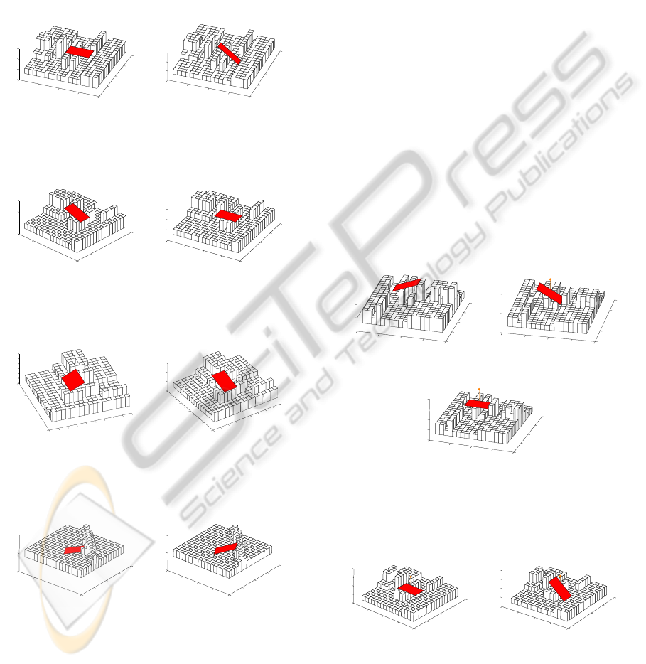
Figure 6: Translation GG1 from (left) to (right), missing
intermediate O-posture.
0
5
10
15
20
0
5
10
15
20
−2
0
2
4
X−direction
Original Map
Y−direction
Z − HIGTH
0
5
10
15
20
0
5
10
15
20
−2
0
2
4
X−direction
Original Map
Y−direction
Z − HIGTH
Figure 7: Translation GG2 from (left) to (right), missing
intermediate M-posture.
0
2
4
6
8
10
12
14
16
18
0
5
10
15
20
−2
−1
0
1
2
3
4
X−direction
Original Map
Y−direction
Z − HIGTH
0
2
4
6
8
10
12
14
16
18
0
2
4
6
8
10
12
14
16
18
20
−2
0
2
4
X−direction
Original Map
Y−direction
Z − HIGTH
Figure 8: Translation GG6 from (left) to (right), missing
intermediate AOP type O-posture.
0
5
10
15
20
0
5
10
15
20
−5
0
5
X−direction
Original Map
Y−direction
Z − HIGTH
0
5
10
15
20
0
5
10
15
20
−5
0
5
X−direction
Original Map
Y−direction
Z − HIGTH
Figure 9: Translation GG8 from (left) to (right), climbing
up through a missed M-posture.
Green → Orange: note that here P
2
=O
1
and cor-
responds to the first part of the O-state before loosing
the balance.
(GO1): G(U)→O(D) is forbidden; it occurs only
if we missed another intermediate O-posture (TR8),
which corresponds to a forbidden sequence O→O
(section 7.1).
(GO2): G(D)→O(U) is similarly forbidden.
(GO3): G(D)→O(D) is a rare case, meaning loos-
ing balance on the edge of the cell while going down
and having a small change in θ
X
or/and θ
Y
.
(GO4): G(D)→O(Z) is an extremely rare case,
which occurs when there is a missed intermediate M-
posture. This mistake results into wrong calculations
and the swap between O
1
and O
2
; without this swap
a jump between P
1
and P
2
would exceed the permit-
ted threshold and P
2
would obtain R-color (Figure10:
while the real posture sequence is a-b-c, the simulator
understands it as a-c-b).
(GO5): G(U)→O so that P
2
has Z
inc
and |θ
Y
| > ε.
This situation occurs due to AOP and is forbidden.
(GO6): G(Z)→O(Z) is the most common case
when the robot passes through the edge of the RSE
cell while going down from the flat top of the
barrier(Figure11).
(GO7): G(U)→O(U) is the most common case
when the robot passes through the edge of the RSE
cell while climbing up to the flat top of the barrier.
0
5
10
15
20
0
5
10
15
20
−2
0
2
4
X−direction
Y−direction
Original Map
Z − HIGTH
(a)
0
5
10
15
20
0
5
10
15
20
−2
0
2
4
6
X−direction
Y−direction
Original Map
Z − HIGTH
(b)
0
5
10
15
20
0
5
10
15
20
−2
0
2
4
6
X−direction
Y−direction
Original Map
Z − HIGTH
(c)
Figure 10: Translation GO4 from G (a) to O
1
(b), followed
by O
2
(c), is missing an intermediate M-posture between (a)
and (b).
0
5
10
15
20
0
5
10
15
20
−2
0
2
4
6
X−direction
Original Map
Y−direction
Z − HIGTH
0
5
10
15
20
0
5
10
15
20
−2
0
2
4
6
X−direction
Original Map
Y−direction
Z − HIGTH
Figure 11: Translation GO6 - going down from the flat top
of the barrier from O
1
(left) to O
2
(right).
While cases GO1, GO2, GO4 and GO5 are recol-
ored into R-posture, cases GO3 should be accepted
only if no other better choice of the path exists.
ICINCO 2010 - 7th International Conference on Informatics in Control, Automation and Robotics
420
Orange → Green : Pairs O→G are exactly the
same as G→G. The only difference is that the second
posture for all cases different from GG3 and GG7 are
recolored as R with regard to section 7.1.
8 SIMULATION
The only real proof of any theoretical hypothesis is
an experimental proof. Thousands of different situ-
ations can occur in a completely random RSE and it
is physically impossible to execute such huge number
of experiments. The exhaustive simulations help us
to conclude which situations can not occur due to the
physical rules of RSE. Pairs of postures, impossible
in the real world, are also impossible within the sim-
ulation. Since the reverse statement is not true, the
simulator can not substitute the experiments, but as-
sists to structure the data and remove the impossible
types of sequences, saving time and efforts.
0
10
20
30
40
50
60
70
80
0
10
20
30
40
50
60
70
80
-1
0
1
2
3
Y-direction
Original Map
X-direction
Z - HIGTH
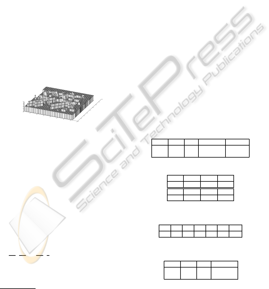
Figure 12: A complicated environment of size 61x61 cells,
covering all main types of the environment obstacles.
We created a huge environment of 61x61 cells
(Figure12) which includes all typical obstacles, usu-
ally appearing in the random step environment: hori-
zontal and diagonal barriers, pairs of parallel barriers,
traversable and non-traversable pikes and holes. For
the simulation we have chosen discretization DISC5.
An exhaustive check of all possible pairs of neighbor-
ing postures connected with a translation step were
proceeded with voting for each group. As a first
robot’s CM posture of the pair we took every node
of the grid
3
; a second posture of the pair was calcu-
lated as a 1-unit length change of CM’s location in the
direction of the robot’s heading direction θ. The total
number of posture pairs was more then 6 millions.
The simulation included 91 robot orientations θ ∈
{0,
π
180
,
2π
180
, ...,
89π
180
,
π
2
}. In addition to pointing at the
impossible (empty) cases the simulation reveals the
rare cases and the most often cases.
The results are summarized in the following ta-
bles. Table 2 presents the distribution of the pair ap-
3
The nodes too close to the borders of the map were
excluded
pearances before recoloring the second posture of the
pair at discretizations DISC2 and DISC5. We listed
as legal pairs GG3, GG7, GO6 and GO7; pairs, con-
taining at least one R-posture are legal as well, but we
present them as a separate case. Undesirable pairs
include fixable cases GG1, GG2, GG4, GG5, GG8,
GG9, GO3, which appearance we still would prefer to
avoid. Forbidden pairs are GG6, GG10, GG11, GO1,
GO2, GO4, GO5, OO, OM, MO and C (second pos-
ture of the pair is cyan). We excluded from the statis-
tics all G→M, M→M and M→G cases, which oth-
erwise would contribute 3.96%. Table 3 presents the
distribution of the forbidden pair appearances in per-
cents from the total pairs at DISC5; pairs GO1, GO2
and GO5 had zero appearance so they are excluded
from the table. C-posture appearance signals on the
missed M-posture. However, such M-posture should
be forbidden, because the height difference between
two G-postures exceeds KENAF’s climbing abilities
threshold: fast vertical change and is too dangerous
when sliding down and impossible when climbing up.
Table 4 presents the distribution of the undesirable
pair appearances in percents from the total pairs at
DISC5. Table 5 presents the distribution after the re-
coloring. For DISC5 legal pair percent varies from
93.1% to 95.84% for different θ choice, which means
we have a wide enough range of options for choosing
a good path at DISC5.
Table 2: Pair distribution in percents for DISC2 and DISC5.
DISC Legal Red Undesirable Forbidden
2 86.74 4.4 4.42 4.43
5 93.21 2.06 1.55 3.18
Table 3: Forbidden pair distribution in percents for DISC5.
GG6 GG10 GG11 GO4
0.33 0.57 1.38 0.009
MO OO OM C
0.011 0.009 0.004 0.862
Table 4: Undesirable pair distribution in percents for
DISC5.
GG1 GG2 GG4 GG5 GG8 GG9 GO3
0.08 0.55 0.66 0.05 0.11 0.1 0.006
Table 5: Pair distribution in percents for DISC2 and DISC5
after the recoloring.
DISC Legal Red Undesirable
2 91.33 8.66 0.03
5 94.61 5.38 0.01
STATIC BALANCE FOR RESCUE ROBOT NAVIGATION - Translation Motion Discretization Issue within Random
Step Environment
421

9 DISCRETISATION ISSUE
The choice of a proper discretization of the search
space is a very complicated task. We started our re-
search with DISC5, which we considered to be good
enough to notice main changes while traversing RSE.
It turned that many of our initial theoretical expecta-
tions of robot’s behavior in RSE did not fulfil. We
called those cases undesirable and started a deeper
exploration of what is happening in such cases.
We discovered, that those unexpected cases ap-
pear only due to the level of the discretization: dis-
cretizing the environment into 17x17mm cells turned
to be too coarse to note all the changes and capture
all the intermediate postures, obtained by the robot
within one translational step. Increasing discretiza-
tion to DISC10 decreases percentage of undesirable
cases, but unfortunately can not solve the problem
completely. If the level of the discretization would
be infinitely high, we would definitely obtain a prop-
erly colored posture between undesirable pair of
postures in every case. Here is a simple exam-
ple of the discretization influence: a small analyt-
ical step from one G-posture to another G-posture
of 10
−28
cm length, approximated by MATLAB as
2.8422 · 10
−14
, resulted into robot orientation change
of {25, −15.5, −17}degrees with regard to global
frame of RSE, signaling about a missed intermedi-
ate posture. This example shows that for any finite
level of the discretization we still will have undesir-
able pairs appearances. Since we can not increase the
discretization infinitely, we concluded that applying
the results of section 7 for recoloring of the states at
DISC5 is a good trade-offbetween executiontime and
precision. Of course, forbidding dangerous and suspi-
cious transition, which still may be theoretically pos-
sible, limits our path choice, but increases the security
of the practical use.
10 CONCLUSIONS AND FUTURE
WORK
The final target of our research is to provide an assis-
tant ”pilot system” for an operator of a rescue robot,
decreasing the burden on the human operator. As
soon as the robot obtains data from the environment
and creates an internal world model, a selection on
the path within the internal model should be done, fol-
lowed by applying this path in the real world scenario.
Since usually there exist more then just a single path,
the path search algorithm needs a good instrument to
evaluate the quality of each path. The search algo-
rithm within the graph requires a proper definition of
neighboringstates to ensure smooth explorationof the
search tree. In this paper we presented our results in
estimation of the transition possibilities between two
consecutive states, connected with a translation step.
It is an important step toward a proper definition of
a search tree neighborhood function F(Args) = Res,
where arguments Args are the robot’s current config-
uration and the environment and output Res is a set
of accessible within one step configurations. We cre-
ated a theoretical basis for function F and confirmed
it with exhaustive simulations; the later were used to
structure, analyze and solve the discretization of the
RSE state space issue problems and help to remove
unsuitable search directions. Next we plan to confirm
our results with experiments and to complete function
F with the theory for the rotation step neighbor node.
ACKNOWLEDGEMENTS
This research has been partially supported by
NEDO Project for Strategic Development of Ad-
vanced Robotics Elemental Technologies, High-
Speed Search Robot System in Confined Space.
REFERENCES
Cormen, T., Leiserson, C., Rivest, R., and Stein, C. (2001).
Introduction to algorithms. In Second Edition. The
MIT Press and McGraw-Hill.
Hirose, S., Tsukagoshi, H., and Yoneda, K. (1998). Nor-
malized energy stability margin: generalized stabil-
ity criterion for walking vehicles. In 1st Int.Conf. On
Climbing and Walking Robots.
Jacoff, A., Messina, E., and Evans, J. (2001). Experi-
ences in deploying test arenas for autonomous mobile
robots. In Proc. of the 2001 PerMIS Workshop.
Latombe, J. C. (1991). Robot motion planning. In Proc.
of the 2001 PerMIS Workshop. The MIT Press and
McGraw-Hill.
Magid, E., Ozawa, K., Tsubouchi, T., Koyanagi, E., and
Yoshida, T. (2008). Rescue robot navigation: Static
stability estimation in random step environment. In
Proc. of Int.Conf. on SIMPAR.
Sheh, R., Kadous, M., Sammut, C., and Hengst, B. (2007).
Extracting terrain features from range images for au-
tonomous random stepfield traversal. In IEEE Int.
Workshop on Safety, Security and Rescue Robotics.
Shoval, S. (2004). Stability of a multi tracked robot travel-
ing over steep slopes. In IEEE ICRA.
ICINCO 2010 - 7th International Conference on Informatics in Control, Automation and Robotics
422
