ANALYSIS AND DESIGN OF COMPUTER ARCHITECTURE
CIRCUITS WITH CONTROLLABLE DELAY LINE
N. V. Kuznetsov, G. A. Leonov, S. M. Seledzhi
Saint-Petersburg State University, Universitetski pr. 28, Saint-Petersburg, 198504, Russia
P. Neittaanm¨aki
University of Jyv¨askyl¨a, P.O. Box 35 (Agora), FIN-40014, Finland
Keywords:
Delay line, Phase locked loop, Nonlinear analysis, Clocked circuit.
Abstract:
In this work classical and modern control theory methods are applied for rigorous mathematical analysis and
design of different computer architecture circuits such as clock generators, synchronization systems and others.
The present work is devoted to the questions of analysis and synthesis of feedback systems, in which there
are controllable delay lines. In the work it is mathematically strictly shown that RC-chain can be used as a
controllable delay line for different problems of circuit engineering if the chain is sequentially connected with
hysteretic relay. This relay is either artificially introduced or shows itself as non-ideality of logic elements.
The possibility of phase-locked loop application for time delay control is considered.
1 INTRODUCTION
The work is devoted to the questions of analysis and
synthesis of feedback systems, in which there are con-
trollable delay lines. First of all this is a class of con-
trollable clock generators and clocked circuits, which
perform the functions of summators (Cormen et al.,
1990).
In clocked circuits it is necessary that the delay
was by the one tact. For this purpose we need in a spe-
cial setting of parameters of delay lines, which will
be described in details. The generators, constructed
on logic elements and delay lines, are not high-stable
with respect to frequency (Ugrumov, 2000). There-
fore, for their stabilization and synchronization by
phase-locked loops it is necessary to introduce a con-
trollable parameter in delay line. A class of such delay
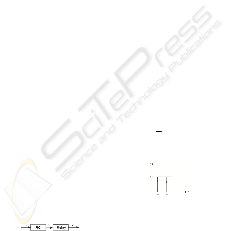
lines, the block-scheme of which is shown in Fig. 1,
is considered.
Figure 1: Delay line.
The RC-chains are often used in circuit engineer-
ing as delay lines (Ugrumov, 2000). We assume that
the relation between the input u and the output x is
described by the following standard equation of RC-
chain
RC
dx
dt
+ x = u(t), (1)
where R is a resistance, C is a circuit capacitance.
The relation between the input x and the output
v is described by the graph of “relay with hystere-
sis”function, which is shown in Fig. 2. Here µ
1
and µ
2
Figure 2: Relay with hysteresis.
are certain numbers from the interval (0,1). The the-
ory and practice of application of such relay blocks in
feedback systems is well described in (Popov, 1979;
Krasnosel’skii and Pokrovskii, 1983).
In the present work we consider only the func-
tions u(t), which takes the values either 0 or 1 on cer-
tain intervals. Therefore, the solutions x(t) of equa-
tion (1) are continuous, piecewise-differentiable and
221
V. Kuznetsov N., A. Leonov G., M. Seledzhi S. and Neittaanmäki P. (2009).
ANALYSIS AND DESIGN OF COMPUTER ARCHITECTURE CIRCUITS WITH CONTROLLABLE DELAY LINE.
In Proceedings of the 6th International Conference on Informatics in Control, Automation and Robotics - Signal Processing, Systems Modeling and
Control, pages 221-224
DOI: 10.5220/0002205002210224
Copyright
c
SciTePress
piecewise-monotone functions. It follows that the
graph in Fig. 2 correctly defines the output v(t). Fur-
ther it will be shown that the hysteretic effect is of
great importance for synthesis both of clock genera-
tors and of clocked summators. This effect always
occurs in real (non-ideal) logic elements. Since the
output of delay line is often the input of logic ele-
ment, it is convenient to connect such hysteretic ef-
fect with RC-chain and to consider it in the frame of
block-scheme in Fig. 1. In some cases for improve-
ment of a quality of delay line operation it is possible
to introduce additional block “relay with hysteresis”,
which provides a required delay time and stability of
system operation.
We can show here the analogy with a classical
study of Watt’s regulator by I.A.Vyshnegradskii (An-
dronov and Voznesenskii, 1949; Leonov, 2001). Re-
call a main conclusion of Vyshnegradskii: “without
friction the regulator is lacking”. But if a friction “is
not sufficient”, then it is possible to introduce a spe-
cial correcting device, dashpot, which provides a sta-
ble operation of system. In the case now being con-
sidered the friction is replaced by hysteretic effect and
the above classical scheme of reasoning is repeated.
This becomes especially clear if we consider the syn-
thesis of clock generators.
For clocked summators it turns out rational the in-
troduction of two-stage delay lines, which shift a unit
impulse for the one tact. The latter permits us to use a
three-bit summator for any summation, confining our
attention to a minimal number of circuit elements.
The application of methods and technique of
the classical control theory (Burkin et al., 1996;
Leonov et al., 1996, Popov, 1979; Krasnosel’skii and
Pokrovskii, 1983; Andronov and Voznesenskii, 1949)
permits us tofind the solution of consideredproblems,
applying very simple mathematical constructions.
2 DELAY LINES FOR SYNTHESIS
OF CONTROLLABLE CLOCK
GENERATORS
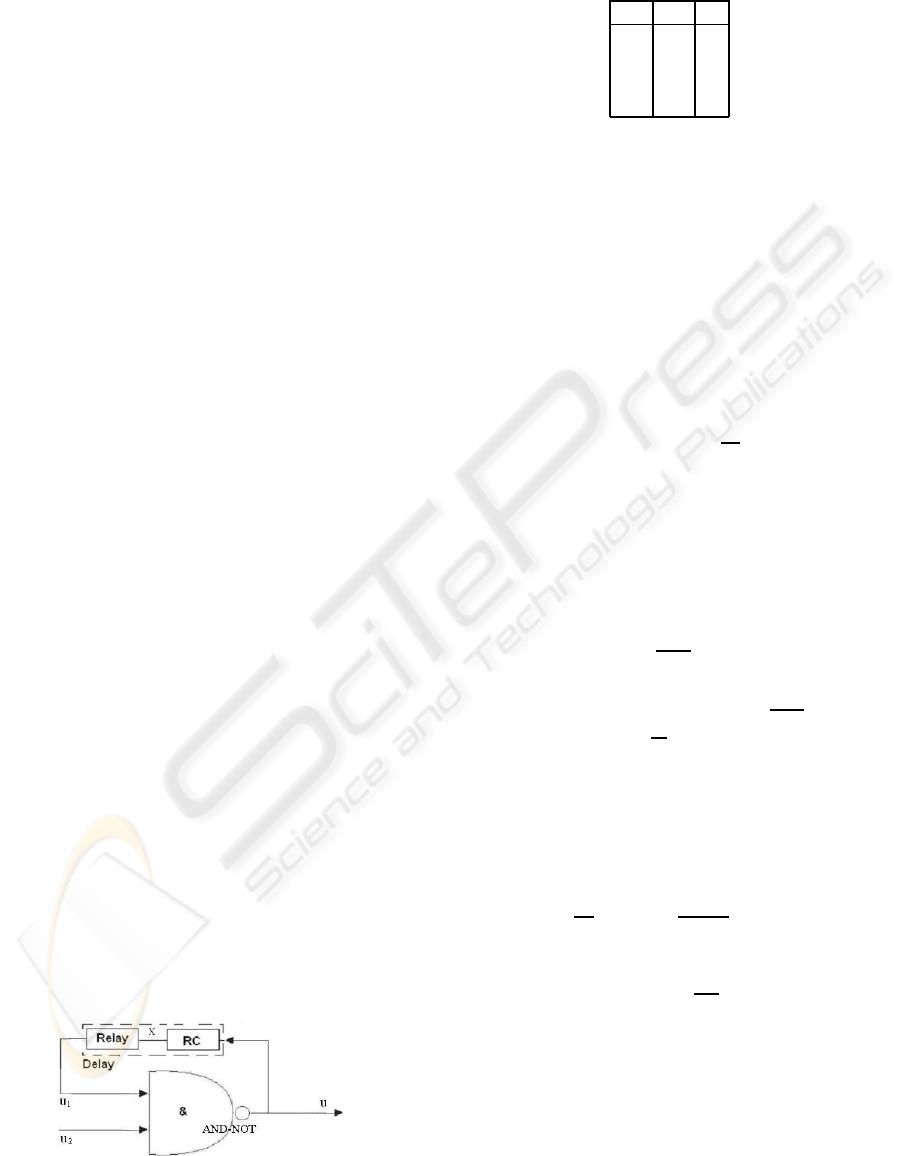
Consider the block-scheme in Fig. 3 and, recall the
Figure 3: Clock generator on Block AND-NOT and delay
line.
table for Block AND-NOT output
u
1
u
2
u
0 0 1
0 1 1
1 0 1
1 1 0
Truth table of Block AND – NOT
Let u
2
(t) = 0 for t < T, T > 0. Then u(t) = 1
for t < T and at the input x(t) there occurs (after a
transient process) the signal x(t) = 1. Suppose, x(t) =
1 on [0,T]. Then u
1
(t) = 1 on [0, T] and a system is
in equilibrium:
1 = u
1
(t) = x(t) = u(t), u
2
(t) = 0.
The inclusion of clock generator is realized by
the change of u
2
from the state 0 to the state 1:
u
2
(t) = 1, ∀t > T. Then on the certain interval (T,T
1
)
we have u(t) = 0. This implies that u
1
(t) = 1 for
t ∈ (T,T
1
), where
T
1
= T + RCln
1
µ
1
(2)
and u
1
(t) = 0 on a certain interval (T
1
,T
2
).
Really, from equation (1) it follows that on (T,T
1
)
we have x(t) = e
−αt
, α = 1/RC. In this case u
1
(t) =
1 for t ∈ (T,T
1
), where T
1
is from relation (2), and
u
1
(t) = 0 for t ∈ (T
1
,T
2
), where T
2
will be determined
below. From the latter relation it should be that u(t) =
1 for t ∈ (T
1
,T
2
). This implies the following relation
T
2
= T
1
+ RCln
1−µ
1
1−µ
2
, x(T
2
) = µ
2
.
In the case when µ
1
= 1−µ
2
, µ
2
∈(1/2,1), we obtain
τ = T
1
−T
0
= T
2
−T
1
= RCln
µ
2
1−µ
2
,
T
0
= T + RCln
1
µ
2
,
and 2τ-periodic sequence at the output u:
u(t) = 0, ∀t ∈ [T
0
,T
0
+ τ),
u(t) = 1, ∀t ∈ [T
0
+ τ,T
0
+ 2τ).
Thus, the block-scheme in Fig. 3 is a clock generator
with the frequency
ω =
1
2τ
=
2Rln
µ
2
1−µ
2
−1
C
−1
. (3)
We compare this frequency with the frequency of har-
monic LC-oscillator:
ω = 1/
√
LC (4)
At present it is developed different methods of
control of a frequency of harmonic oscillators by
means of a slow (with respect to the high frequency
ω) change of parameter C. It is especially widely ex-
tended the phase-locked loops (Viterbi, 1966; Lind-
sey, 1972). In the past decade similar constructions
are actively developed and applied to the clock gener-
ators with frequency (3) (Solonina et al., 2000).
ICINCO 2009 - 6th International Conference on Informatics in Control, Automation and Robotics
222
3 DELAY LINES FOR CLOCK
IMPULSES
Consider the delay line, the block-scheme of which is
shown in Fig. 1. Let u(t) be 2τ-periodic sequence of
impulses:
u(t) = 0,∀t ∈ [0,τ), u(t) = 1,∀t ∈ [τ,2τ). (5)
If we choose the initial data x(0, x
0
) = x
0
so that the
relation
τ = RCln
x
0
1−x
0
, x
0
∈ (1/2,1), (6)
is satisfied, then x(τ,x
0
) = 1 −x
0
, x(2τ,x
0
) = x
0
.
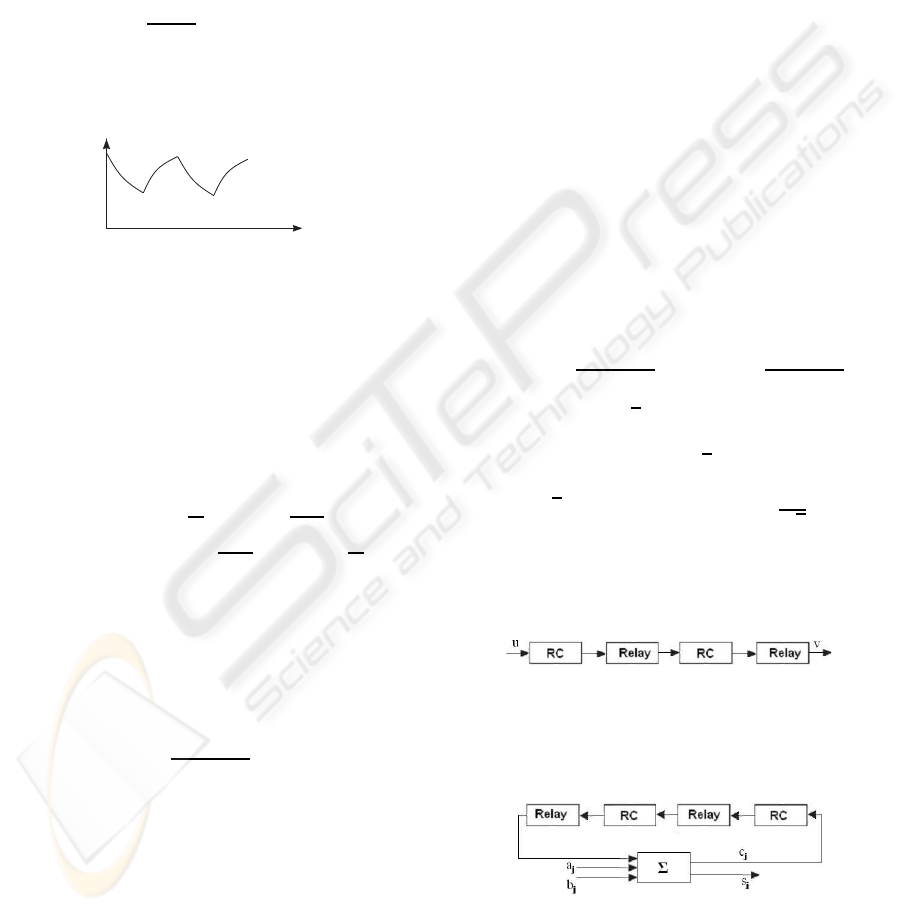
In this case the graph of 2τ-periodic function x(t) is
shown in Fig. 4.
x
0
1-x
0
t
2t
3t
4t
t
.
.
. .
Figure 4: Periodic output of RC-chain.
It is well known (Leonov, 2001) that for all other
solutions of equation (1) x(t,y
0
) the following relation
lim
t→+∞
(x(t,x
0
) −x(t,y
0
)) = 0 (7)
is satisfied. If we choose x
0
> µ
2
, 1 −x
0
< µ
1
, then
relation (7) implies that after transient process, at the
output v (of delay line) we obtain 2τ-periodic se-
quence of impulses:
v(t) = 0, ∀t ∈
h
RCln
x
0
µ
1
,τ+ RCln
x
0
1−µ
2
,
v(t) = 1, ∀t ∈
h
τ+ RCln
x
0
1−µ
2
,2τ+ RCln
x
0
µ
1
.
(8)
Note that for µ
1
= 1−x
0
+ε, µ
2
= x
0
−ε, where ε > 0
is a small parameter, from (8) we have
v(t) = 0, ∀t ∈ [τ
ε
,τ+ τ
ε
),
v(t) = 1, ∀t ∈ [τ+ τ
ε
,2τ+ τ
ε
),
(9)
where
τ
ε
= RCln
x
0
1−x
0
+ ε
−−→
ε→0
τ. (10)
Recall that x
0
∈ (1/2,1) and τ is determined from
relation (6).
Thus, the block-scheme in Fig. 1 realizes asymp-
totically the time delay τ: after transient process (see
relation (7)) at the output v we observe relation (9), in
which case relation (10) is satisfied.
Consider now a certain extension of the above
case. Let u(t) be a certain sequence of clock impulses
(not necessarily 2τ-periodic) such that
u(t) = 0, ∀t ∈ [2kτ,(2k+ 1)τ), k = 0,1,.. .
and on each of intervals ((2k + 1)τ,2k + 2)τ) it can
take the value either 0 or 1.
Now we consider the case when the delay line op-
erates in working conditions after transient process.
In this case, taking into account the above reasoning,
we can assume that for the certain fixed k there occur
the following restrictions:
u(t) = 1, ∀t ∈ [(2k+ 1)τ,2(k + 1)τ)
x((2k+ 1)τ) ∈(0,1−x
0
),
where x
0
satisfies relation (6).
We shall show that in this case it can be made such
a choice of parameters of delay line, for which asymp-
totically (at ε →0) the delay time of unit impulse is τ.
For this purpose we can take the obvious inequalities
x(t,(2k + 1)τ,0) ≤ x(t,(2k + 1)τ,x((2k + 1)τ) ≤
≤ x(t,(2k+ 1)τ,1−x
0
), ∀t ≥ (2k+ 1)τ.
Here x((2k+ 1)τ,(2k+ 1)τ,y
0
) = y
0
. By the previous
relations µ
1
= 1−x
0
+ ε, µ
2
= x
0
−ε we obtain
v(t) = 0, ∀t ∈ ((2k+ 1)τ,(2k+ 1)τ+ τ
ε
),
v(t) = 1, ∀t ∈ ((2k+ 1)τ +
e
τ
ε
,(2k + 1)τ+ τ
ε
+
e
e
τ
ε
).
Here
e
τ
ε
= RCln(
1
1−x
0
+ ε
),
e
e
τ
ε
= RCln(
x
0
−ε
1−x
0
+ ε
).
Choosing x
0
= 1 −
√
ε, we obtain the following for-
mulas for parameters of delay line, which shifts unit
impulse with accuracy up to
√
ε for time τ:
µ
1
=
√
ε
+ε,µ
2
= 1−µ
1
,RC = τ/ln
1
√
ε
.
(11)
This implies that for the asymptotical shift of unit im-
pulse for time 2τ it is necessary to apply two-stage
delay line with parameters (11) (Fig. 5). We proceed
Figure 5: Two-stage delay line.
now to the clocked circuits for bit summation (Cor-
men et al., 1990) (Fig. 6). Here Σ is a standard sum-
Figure 6: Clocked summator.
mator, at the input of which we have three bits, c
0
= 0.
As the delay line we can use a two-stage delay line
with parameters (11) (Fig. 5). The time between the
ANALYSIS AND DESIGN OF COMPUTER ARCHITECTURE CIRCUITS WITH CONTROLLABLE DELAY LINE
223

arrival of the signals a
j
and a
j+1
(and also b
j
and
b
j+1
) is equal to τ. It is easily seen that the output
s
k
s
k−1
... s
0
is a sum of two numbers a
k−1
a
k−2
... a
0
and b
k−1
b
k−2
... b
0
. Thus, the delay line considered
permits us to construct the summators with minimal
number of circuit elements.
4 CONCLUSIONS
In the present work it is mathematically rigorously
shown that RC-chain can be used as a controllable de-
lay line for different problems of circuit engineering
if the chain is sequentially connected with hysteretic
relay. This relay is either artificially introduced or
shows itself as non-ideality of logic elements.
ACKNOWLEDGEMENTS
The work was partly supported by the projects RFFI
07-01-00151, LSS-2387.2008.1, AVZP-2.1.1/3889.
REFERENCES
Andronov, A.A., Voznesenskii, I.N., 1949. About the works
of D.K. Maxwell, I.A. Vyshnegradskii and A. Stodola
in the field of control theory. M.: Izd. AN USSR.
Burkin, I.M., Leonov, G.A., Shepeljavy, A.I., 1996. Fre-
quency Methods in Oscillation Theory. Dordrecht:
Kluwer.
Cormen, T.H., Leiserson, C.E., Rivest, R.L., 1990. In-
troduction to Algorithms. Cambridge, Massachusetts:
MIT Press.
Horowitz, P., Hill, W., 1998. The Art of Electronics. Cam-
bridge Univ. Press.
Krasnosel’skii, M.A. and Pokrovskii, A.V., 1983. Systems
with hysteresis. M.: Nauka.
Kuznetsov, N.V., 2008. Stability and Oscillations of Dy-
namical Systems: Theory and Applications Jyv¨askyl¨a
Univ. Press.
Leonov, G.A., 2006. Phase synchronization. Theory and
Applications Automation and remote control, N 10,
pp. 47–85. (survey)
Leonov, G.A., Seledzhi, S.M., 2005. Design of Phase-
Locked Loops for Digital Signal Processors, Int. J.
Innovative Computing, Information & Control. Vol.1,
N4, pp. 1–11.
Leonov, G.A., 2001. Mathematical problems of control the-
ory. World Scientific.
Leonov, G., Ponomarenko, D., Smirnova, V., 1996.
Frequency-Domain Methods for Nonlinear Analysis.
Theory and Applications. World Scientific.
Lindsey, W., 1972, Synchronization systems in communica-
tion and control, Prentice-Hall.
Popov, E.P., 1979. The theory of nonlinear systems of auto-
matic regulation and control. M.: Nauka.
Solonina, A., Ulahovich, D., Jakovlev, L., 2000. The Mo-
torola Digital Signal Processors. BHV, St. Petersburg.
(in Russian)
Ugrumov, E., 2000. Digital engineering, BHV,
St.Petersburg. (in Russian)
Viterbi, A., 1966. Principles of coherent communications,
McGraw-Hill. New York.
ICINCO 2009 - 6th International Conference on Informatics in Control, Automation and Robotics
224
