
SHARED MANIPULATION OF 3D OBJECTS FOR
COLLABORATIVE MOBILE MAINTENANCE
Kwan-Hee Lee
Ubiquitous Fusion Research Department, RIST Ulsan Lab. For Industrial Technology
41-10, Maegok Industrial Complex, Bukgu, Ulsan 683-420, Korea
Sung-Je Hong
Dept. of Computer Science and Engineering, Pohang University of Science and Technology
31 San Hyoja-Dong Pohang 790-784, Korea
Jeong-Sik Kim
Convergence Business Unit, KT Research and Development Center
17 Woomyeon-dong Seocho-gu Seoul, 137-792, Korea
Keywords: Mobile Maintenance, Shared Manipulation, Collaboration.
Abstract: We present an effective method for sharing 3D models over the network, while supporting the same viewing
environment and collaborative manipulation of 3D objects with applications to remote maintenance of
industrial equipments. The 3D models are first presented in a top-down manner, which facilitates an
intuitive understanding of their hierarchical structure. The kinematic structure is also presented so as to
explain the moving mechanism of 3D models. Part assembly/disassembly is a basic procedure in part
maintenance, which is shown in animation clips as well as in diagrams. To maintain the viewing
environment consistent, we synchronize the result of model operations by sharing only a small number of
state variables over the network. We don’t reply on a separate server or a lock/unlock mechanism for the
synchronization. As a result, we support an efficient manipulation of complex 3D models shared over the
network. The developed system provides an intuitive interface and demonstrates an interactive performance.
1 INTRODUCTION
In manufacturing factories, the reliability of unit
facilities is an important factor for keeping the
production line flow continuously without
interruption. When industrial equipments do not
work properly, they break the continuity of
production and the productivity of the factory will
drop as a consequence. It is thus very important to
have an effective maintenance system that can fix
malfunctioning equipments quickly while imposing
relatively low repair cost (Wang, J.F. et al., 2004).
The reclaimer is an industrial equipment used for
steelworks; this equipment digs up raw material
from a huge pile and puts the material on a transfer
conveyor belt, which is then fed to the production
line (Choi, C.-T. et al., 1999). In the maintenance
database of Kwangyang Steelworks in Korea, it is
observed that minor malfunctions occur more
frequently than major ones. In particular, only 1.4%
of malfunctions are major ones, which should be
fixed by the maintenance expert. In this case, the
expert should be physically present in the field. On
the other hand, the rest of malfunctions can be
handled by less-experienced operators possibly by
consulting (over the phone) with the maintenance
expert located at a remote site.
There is a close correlation between the
malfunctions and their causes, which makes
effective management of maintenance manpower
even more difficult since similar malfunctions occur
simultaneously in many different reclaimers. To
resolve this problem, we need to develop an
interactive system that can support effective
285
Lee K., Hong S. and Kim J. (2009).
SHARED MANIPULATION OF 3D OBJECTS FOR COLLABORATIVE MOBILE MAINTENANCE.
In Proceedings of the First International Conference on Computer Supported Education, pages 285-289
DOI: 10.5220/0001962102850289
Copyright
c
SciTePress
communication between the operators and the
maintenance experts located at remote sites. For this
purpose, it is convenient to present the operation
mechanism of equipments in a shared environment
of 3D models over the network. As a 3D CAD
conference system, CSpray (Pang, A., and
Wittenbrink, C., 1997) provides the shared viewing
environment of data to the distributed users. On the
other hand, e-Assembly (Chen, L. et al., 2004)
supports the 3D model manipulation and
collaborative assembly modeling function. While
server based systems such as these examples can
support the collaboration environment for multi-
users, they do not support the assembly/disassembly
procedure or operation mechanism for maintenance
since they include no kinematic information.
This paper proposes an interactive maintenance
system that supports, at an interactive speed, a
shared manipulation of 3D models, a shared viewing
of scenes, and the presentation of operation
mechanisms and assembly/disassembly procedures.
This system facilitates an effective maintenance of
industrial equipments. The same viewing
environment is shared among multi-users, while
each user can use a screen of different size and
resolution. There is no need of a separate server for
handling the consistency of viewing or model
manipulation. The logical structure of 3D models is
presented in a top-down hierarchical manner; on the
other hand, their kinematic structure is represented
using the connectivity of joints, which controls the
motion of the mechanism. It also presents the
procedures for part assembly and disassembly,
which are useful in replacing parts.
2 MODEL STRUCTURE AND
VISUALIZATION
The maintenance of industrial equipments proceeds
in three main steps: (i) problem area diagnosis, (ii)
operation inspection, and (iii) parts
disassembly/assembly. Diagnosis of the problem
area requires an intuitive understanding of the
overall structure of the industrial equipment, for
which a top-down hierarchical classification of the
3D models is quite useful. For the operation
inspection, the moving mechanism is effectively
described by the kinematic structure of internal
joints of the model. Moreover,
assembly/disassembly procedures describe how to
replace broken parts effectively.
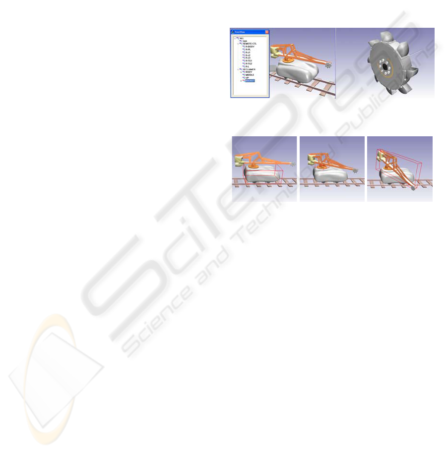
2.1 Intuitive Structure
A top-down tree structure is commonly used by the
operators to classify the parts of equipment
according to the general classification rules, which
facilitates the understanding of the overall structure
of equipment. Figure 1 shows how industrial
equipment is intuitively represented using a top-
down dialog consisting of part names. The left side
of Figure 1 shows the overall shape of the equipment,
and the right side shows the details of a part selected
from the top-down dialog.
Figure 1: Intuitive structure description using a top-down
hierarchy.
Figure 2: Kinematic structure(Traveling axis, slewing axis
and pitching axis).
2.2 Kinematic Structure
The hierarchical structure is used to improve an
intuitive understanding of the typical body
classification. Nevertheless, it does not describe the
kinematic structure of the equipment. The
connectivity of internal joints determines the
kinematic structure of the model. In the kinematic
structure of the reclaimer, the parts are linked in the
order of BODY, MIDDLE, UP, and BUCKET. The
transfer of motions occurs in this order from a
moving part to all consecutive parts.
Figure 2 shows the structure presented from a
kinematic point of view. To manipulate the
equipment, a part selected from the top-down dialog
is rotated or translated. Its motion is then
transformed according to its kinematic attributes and
transferred to the dependent parts in the kinematic
structure.
CSEDU 2009 - International Conference on Computer Supported Education
286
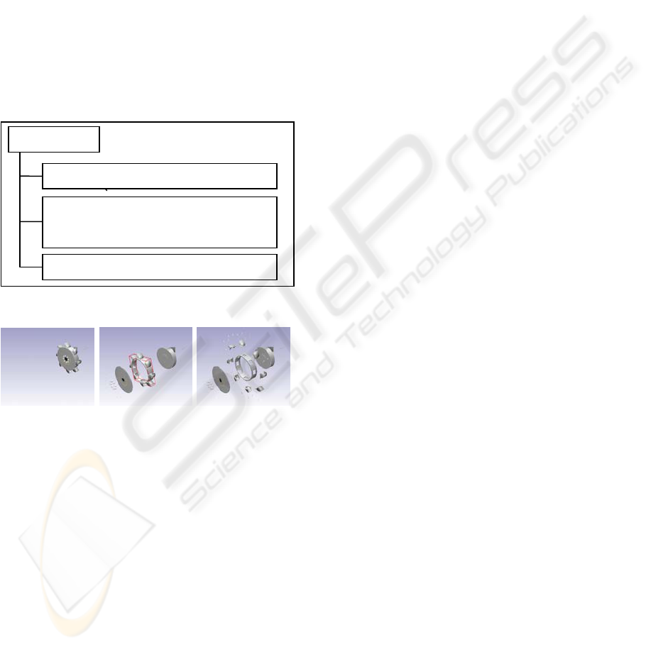
2.3 Assembly/ Disassembly Structure
The assembly/disassembly of the parts involves
separating subparts of a part and combining subparts
into their main part. Therefore,
assembly/disassembly cannot be represented in the
kinematic structure. (The connectivity between the
main part and its subparts is different from the
connectivity of internal joints.) Thus we need an
additional description for the assembly/disassembly
procedures. As shown in Figure 3, disassembly is
presented in a scenario, which describes the relative
translation range of the subparts from the main part
and the group or subpart names showing the order of
disassembly. Assembly procedure works in the
reverse order of the disassembly. Figure 4 shows the
bucket disassembly.
Figure 3: Assembly/disassembly scenario.
Figure 4: Disassembly of a Part.
3 SHARING OVER THE
NETWORK
A consistent view of 3D virtual space shared over
the network enhances the sense of presence and
enables effective communication (Hamza-Lup, F.G.,
and Rolland, J.P., 2004). Absolute consistency can
be maintained by mutually excluding the operations
that may cause inconsistency. The concurrency
control mechanism using the lock/unlock technique
(Linebarger, J.M., and Kessler, G.D., 2004) is a
method of mutual exclusion; however, this approach
imposes much computational burden to the
interactivity of the system. Interactivity and
consistency are often required at the same time. In
the case of on-line gaming environments, where
separate servers are used for resource sharing, the
Interactivity-Loss Avoidance approach (Palazzi,
C.E., et al. 2004) is commonly used as a trade-off
between the two conflicting requirements. This
approach tries to avoid the loss of interactivity
before it happens, even discarding some packets
when the level of interaction degrades significantly.
In this paper, we propose a method that directly
connects two clients with no server employed for
resource sharing. The consistency is effectively
maintained by sharing only a small number of state
variables. Only a few updated variables are
transferred over the network for an effective sharing
of the 3D viewing environment, the operating
condition of each part, and the application program
status.
3.1 Synchronization of Two Clients
As shown in Figure 5, the user interaction can be
divided into viewing transformations, object
transformations, selection of the menus, etc. The
result of each unit interaction is transferred to the
other party through the TCP/IP socket, and the result
of the interaction by the other party, received
through the TCP/IP socket, updates the shared
variables.
Note that the mutual transfer of the manipulation
result cannot guarantee 100% absolute consistency
since each party will view the result of the
manipulation of the other party while both parties
simultaneously send and receive the results of
different manipulations. When each client performs
operations independent of those in the other party
(e.g., one client performs viewing transformations
and the other performs object manipulations),
consistency is guaranteed. However, when order-
dependent operations are simultaneously performed
(e.g., translations and rotations) in both clients,
inconsistency may occur, in particular, in a low
speed network. The inconsistency problem may
occur when the time difference (t
σ
= T
R
− T
S
)
between the most recent sending (T
S
) and the current
receiving (T
R
) time is less than the time delay (2⋅T
d
)
for an interaction delivery to the other party (see
Table 1). This means that the current operation just
received might have been generated by the other
party earlier than the previous one that had been sent
to the other party at t
σ
time ago. We solve the
inconsistency problem using a method that the client
of a higher priority sends a synchronization signal to
the other party when t
σ
is less than 2⋅T
d
(see Figure
5).
Scenario Name
(Group | Part Name)
1
, Relative Translation Range
...
(Group | Part Name)
k
, Relative Translation Range
...
(Group | Part Name)
n
, Relative Translation Range
SHARED MANIPULATION OF 3D OBJECTS FOR COLLABORATIVE MOBILE MAINTENANCE
287
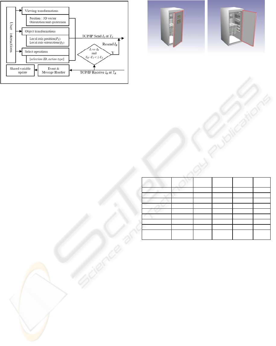
Figure 5: Data transmission structure : sending interaction
(I
S
), sending time stamp (T
S
), receiving interaction (I
R
),
receiving time stamp (T
R
), time delay for an interaction
delivery (T
d
), operator for checking order-dependent
operation(⇔).
The characteristics of the communication
between the operator and the maintenance expert
also ensure that one-way data transfer occurs more
often than simultaneous manipulation, thus making
this method practically effective. Unless order-
dependent operations are generated simultaneously
by both parties, two clients can always maintain a
consistent view. This approach reduces network
traffic significantly since it requires no resource
sharing through a server. Since mutually exclusive
operations are not restricted, various intuitive
interactions can be implemented considerably easily,
compared to the existing methods. The developed
system works at an interactive speed.
3.2 3D Model Sharing
A 3D model is shared over the network by
sending/receiving only the updated information,
instead of the entire model (Nishino, H. et al., 1999).
The position and orientation of an object can be
determined by the kinematic structure of the object,
assuming that all objects undergo rigid-body
motions. Network data transfer can be reduced by
transmitting only the updated data of the selected
joint, not the entire kinematic information of the
object. In this case, dependent parts of the object are
automatically updated by the other party.
The viewing environment and the 3D models in
the clients are synchronized with minimal data
transfer considering the network latency. We
maintain the consistency of the 3D models by
sharing the local axis position (P
L
) and orientation
(Q
L
) for the case of part transformation (see Figure
5).
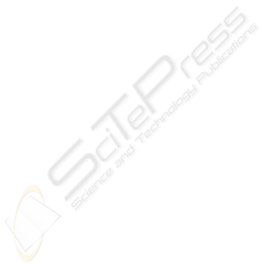
(a) (b)
Figure 6: 3-D model sharing.
As shown in Figure 6, the shared object is
marked by a red boundary. For an object with a
manipulation attribute, the transformation of the
object is also enabled and may be manipulated
continuously. In this case, only the position and
orientation of the local axis of the object are
transferred to enable real-time, continuous
observation of the manipulation by the other party.
The viewing transformation for the shared
manipulation and detailed view of selected object
can also be supported simultaneously.
Table 1: Network comparison : average time(sec) in 10
trials.
100Mbps 10Mbps
802.11b
(11Mbps)
802.11g
(54Mbps)
Mobile
Comm.
Initialization 0.9 5.6 22.7 10.1 571.4
scenario 1 229.9 229.5 229.5 229.9 251.0
scenario 2 16.0 15.9 16.0 16.2 17.3
scenario 3 18.4 18.5 18.4 18.4 20.2
scenario 1 +
α
250.7 251.2 251.3 251.0 251.3
scenario 2 +
α
17.6 17.6 17.6 17.7 17.6
scenario 3 +
α
20.0 20.2 20.8 20.3 20.4
Time delay(T
d
) < 0.6 < 0.6 < 0.6 < 0.6 < 1.3
Converging
Time(T
c
)
< 0.9 < 0.9 < 0.9 < 0.9 < 1.8
4 EXPERIMENTAL RESULTS
Table 1 shows the results of evaluating network
performance using the 100Mbps and 10Mbps wired
networks, 802.11b(11Mbps) and 802.11g(54Mbps)
wireless networks, and mobile communications
network (CDMA, forward link: up to 2.4Mbps;
reverse link: up to 153Kbps (CDMA USB Modem
CCU-550, 2008). The initialization time in the table
denotes the time taken for downloading data when
the model (5.7MB) is initially not available in the
client PC. The operation time refers to the time
required to transmit the operation result to the other
client. The term
α
indicates that a continuous
viewing transformation is shared while processing a
scenario. As shown in Table 1, the performance of
the initialization step for sending bulk data is mainly
CSEDU 2009 - International Conference on Computer Supported Education
288
dependent on the network speed. In the shared 3D
manipulation method, however, the system
performance of operation sharing is somewhat
irrelevant of the network speed. The comparison of
“scenario i” and “scenario i +
α
” shows that the
performance of operation sharing mainly depends on
the hardware performance of clients.
In Table 1, T
d
is the average time delay for an
interaction delivery to the other party, and T
c
is the
converging time for maintaining consistency when
dependent operations are carried out simultaneously.
When the two clients are simultaneously involved in
viewing transformation, object manipulation, or
object selection, the test result shows that there is
correlation between the operation type and the
converging time. Since consistency is guaranteed
when independent operations are performed, the
converging time is the same as T
d
. However, for
dependent operations, the converging time (T
c
) is
larger than T
d
since the client of a higher priority
sends a synchronization signal.
5 CONCLUSIONS
We have presented an efficient method for sharing
the manipulation of 3D objects and their viewing
environment over the network. Based on the
proposed method, we have also developed a
collaborative mobile maintenance system that can
support effective communication between a
maintenance expert and a less-experienced operator
at an interactive speed over the Internet.
Compared with other conventional techniques
for modeling and processing 3D objects, the
problem of data sharing over the network entails
different ways of representing and manipulating the
3D models. In the current work, we have considered
only a small number of state variables to be shared
over the network. According to our experiment
results, the network capacity of today can deal with
sharing a reasonably large number of state variables
at an interactive speed. Thus we can apply the
proposed approach to considerably more complex
3D models over the network. Nevertheless, the data
structure for representing and manipulating these
network-sharable 3D models would considerably be
different from conventional ones.
We believe that techniques for procedural
modeling of complex 3D objects will play an
important role in this new direction of research in
geometric modeling and processing. In future work,
we will investigate a systematic way of utilizing
previous techniques for procedural modeling in
various important applications of 3D data sharing
over the network.
REFERENCES
CDMA USB Modem CCU-550. Online at
http://www.cmotech.com/eproduct6-1.htm, accessed
on 10. Nov. 2008.
Chen, L., Song, Z., and Feng, L., 2004. “Internet-enabled
Real-time Collaborative Assembly Modeling via an e-
Assembly System : Status and Promise,” Computer-
Aided Design, 36, pp 835-847.
Choi, C.-T., Lee, K.-H., Shin, K.-T., Hong, K.-S., and Ahn,
H.-S., 1999. “Automatic Landing Method of a
Reclaimer on the Stockpile”, IEEE Transactions on
System, Man, and Cybernetics-Part C : Applications
and Reviews, Vol. 29, No. 1, Feb., pp.308-314.
Hamza-Lup, F.G., and Rolland, J.P., 2004. “Scene
Synchronization for Real Time Interaction in
Distributed Mixed Reality and Virtual Reality
environments,” Presence: Teleoperators & Virtual
Environments, Special Issue: Collaborative Virtual
Environments, Volume 13, Issue 3, MIT Press,
Cambridge, MA, USA, June.
Linebarger, J.M., and Kessler, G.D., 2004. "Concurrency
Control Mechanisms for Closely Coupled
Collaboration in Multithreaded Peer-to-Peer Virtual
Environments," Presence: Teleoperators and Virtual
Environments, Vol. 13, Issue 3, pp. 296-314, Jun.
Nishino, H., Utsumiya, K., Sakamoto A., Yoshida, K., and
Korida, K., 1999. “A method for sharing interactive
deformations in collaborative 3D modeling,”
Proceedings of ACM VRST, pp. 116-123, Dec.
Palazzi, C.E., Ferretti, S., Cacciaguerra, S., and Roccetti
M., 2004. “On Maintaining Interactivity in Event
Delivery Synchronization for Mirrored Game
Architectures”, Proc. of NIME’04, pp. 157-165, Dallas,
TX, USA.
Pang, A., and Wittenbrink, C., 1997. “Collaborative 3D
Visualization with CSpray,” IEEE Computer Graphics
Applications, 17(2), pp.32–41.
Wang, J.F., Tse, P.W., He, L.S., and Yeung, R.W., 2004.
“Remote sensing, diagnosis and collaborative
maintenance with Web-enabled virtual instruments
and mini-servers,” International Journal of Adv.
Manufacturing Technology, pp. 764-772.
SHARED MANIPULATION OF 3D OBJECTS FOR COLLABORATIVE MOBILE MAINTENANCE
289
