
RAPID VISION APPLICATION DEVELOPMENT USING HIVE
A Modular and Scaleable Approach to Vision System Engineering
Gregor Miller, Amir Afrah and Sidney Fels
Human Communication Technology Laboratory, University of British Columbia, Vancouver, Canada
Keywords:
Computer vision, Middleware, Sensor fusion, Distributed processing.
Abstract:
In this paper we demonstrate the use of Hive as a novel basis for creating multi-sensor vision systems. Hive
is a framework in which reusable modules called drones are defined and connected together to create larger
systems. Drones are simple to implement, perform a specific task and using the powerful interface of Hive can
be combined to create sophisticated vision pipelines. We present a set of drones defined within Hive and a suite
of applications built using these drones which utilize the input from multiple cameras and a variety of sensors.
Results demonstrate the flexibility of approaches possible with Hive as well as the real-time performance of
the Hive applications.
1 INTRODUCTION
This paper presents Hive as a novel framework for
rapidly developing vision applications. The Hive ar-
chitecture and communication system was presented
in (Afrah et al., 2008), which demonstrated the ad-
vantages of a layered architecture and a flexible me-
diation mechanism. This paper first discusses the de-
velopment of drones (dumb modules which perform
a specific task) and then describes a suite of appli-
cations constructed by forming pipelines using the
drones. The aim of this paper is to demonstrate that
once a set of well-defined drones are implemented,
vision application development is both simpler and
more efficient.
Multi-sensor systems are of interest since they can
exploit redundancy of data from a variety of sensing
technologies to compensate for the shortcomings of
a single sensor. In addition to potentially increas-
ing the functionality and accuracy of a system, em-
ploying multiple sensors can also decrease the anal-
ysis complexities of single sensor applications (Luo
et al., 2002). The advantages offered by multi-sensor
use are especially evident in vision systems where
analysis complexity and accuracy of results often
pose issues. Employing additional cameras and other
complementary technologies leads to interesting and
promising vision based applications.
The overhead of dealing with a diverse set of tech-
nologies, interfaces and protocols provided for the
sensors in combination with the non-trivial and com-
plex task of analysing images makes vision based
multi-sensor application development quite challeng-
ing. There is a often a large effort required in setting
up and using such networks; system developers are
often faced with issues such as compatibility, com-
munication, performance, etc. in order to build and
prototype multi-sensor systems.
Hive is a component based platform for creat-
ing distributed vision systems. In addition Hive pro-
vides the necessary framework, standardization and
abstraction required for developing sensor fusion net-
works in a simple and plug-in fashion using reusable
modules (drones). We present an overview of Hive in
Section 2, describe a set of drones (Section 3) and the
applications built from them (Section 4). Results, pre-
sented in Section 5, demonstrate the example vision
systems and the performance of their components.
There are not many other systems similar to Hive
in the computer vision literature. OpenCV is a library
which provides an extensive set of image processing
routines while offering moderate support for image
and data I/O (Bradski and Kaehler, 2008). OpenCV
attempts to provide methods for data access and pro-
cessing through a function based interface, however
it is mostly focused on implementing complex algo-
rithms and does not address issues essential in multi-
sensor networks such as control and data manage-
ment.
YARP and Player are two widely used frame-
works for sensor fusion in robotics (Metta et al.,
2006; Gerkey et al., 2001). These platforms pro-
101
Miller G., Afrah A. and Fels S. (2009).
RAPID VISION APPLICATION DEVELOPMENT USING HIVE - A Modular and Scaleable Approach to Vision System Engineer ing.
In Proceedings of the Fourth International Conference on Computer Vision Theory and Applications, pages 101-108
DOI: 10.5220/0001805401010108
Copyright
c
SciTePress

vide mechanisms for communication between differ-
ent modules in a robot. YARP focuses on providing
high level access to OS functionality, and while it ad-
dresses communication and uniform access for indi-
vidual sensors, it does not provide external control
and requires a custom YARP layer for each applica-
tion. Hive is a generic system with drones that are
connected by applications, giving greater flexibility
and control over pipeline creation. Player provides
a multi-threaded framework that facilitates commu-
nication between multiple devices. Player’s architec-
ture supports robotic based networks however it does
not provide the flexibility and control requirements in
creating diverse vision systems.
Various interfaces have been developed to ac-
cess data from input devices, from OS specific ex-
amples such as DirectShow on Windows, Quick-
time and Video4Linux (Schimek et al., 2008), to
cross-platform libraries such as OpenCV (Bradski
and Kaehler, 2008). These systems are generally lim-
ited to capturing data from devices physically con-
nected to the machine the software runs on. One of
our goals with Hive is to develop a generic camera
framework so that data can be captured from a vari-
ety of devices and delivered to any machine on the
network. This involves writing a hive drone for each
capture API, which could be for a specific camera, a
range of cameras (from the same manufacturer), or a
particular platform (e.g. Quicktime). Once all these
drones are created, it is possible to capture data with
very little development effort on any platform.
2 HIVE
Hive is a middleware platform which abstracts sys-
tem specifics and allows communication between ar-
bitrary reusable modules called drones. The plat-
form is based on a layered architecture that provides a
plug-in interface over an event system and a transport
layer that allow for distributed processing. The Hive
architecture and framework is explained in detail in
(Afrah et al., 2008), while the following presents a
brief overview of the important components.
Hive systems are built from drones: reusable mod-
ules which perform a specific task (e.g. capture im-
ages from a camera), and have well-defined inputs
and outputs. Applications are the command-and-
control centres for drones, configuring and connect-
ing sets of drones into processing structures called
swarms to perform a sequence of tasks. Applica-
tions can collate the output from drones to construct a
larger more sophisticated system.
Applications may construct multiple swarms, ei-
ther to distribute processing of a computationally in-
tensive task or to perform various tasks simultane-
ously, and later combine the results. There may also
be multiple applications using the same drones to re-
ceive and process information.
3 DRONES
Hive drones form the basis of vision systems, per-
forming data capture and processing. Drones are cre-
ated by registering functions as handlers for incom-
ing data, and registering a main method which runs
once per drone cycle. The expected type of input and
output are also specified in the drone definition. The
system specifics issues and communication methods
are taken care of by Hive, making the construction of
new drones a trivial task.
The following sections present an overview of the
drones currently operational in our systems.
3.1 Data Capture
All vision algorithms work on input from sensors,
from digital cameras to laser range scanners. Sensors
are abstracted as drones in Hive, exposing their ser-
vices across a network to other processing drones and
applications. The data capture drones we currently
have are as follows:
AXIS Camera. Data is captured from an AXIS
network camera over TCP/IP using the AXIS API
(VAPIX, 2008). The drone is executed from any
computer with access to the network and retrieves
the JPEG compressed image from the camera. The
image is then sent to other Hive modules in either
JPEG or decompressed format.
Inputs: None
Outputs: Colour image
Configuration: Camera settings;
Output format (JPEG or raw)
Image Sequence. When testing algorithms often
the same sequence needs to be used for evaluation
purposes, or the data for a particular application was
pre-recorded. This drone loads an image sequence
from disk and allows seamless switching of data
sources, e.g. from a live camera to an image sequence
stored on any computer on the network. The drone
itself can load any image sequence stored on its local
machine. The root name of the sequence and the
frame rate to supply data are given as configuration
parameters. The Image Sequence drone also supports
video files. Counterparts for storing image sequences
VISAPP 2009 - International Conference on Computer Vision Theory and Applications
102

and video to disk are also available.
Inputs: None
Outputs: Colour image
Configuration: Root filename;
Frame rate
Fastrak. Having a notion of spatial position is an
important aspect of many vision applications. Vision
based algorithms for estimating 3D position require
intensive processing and are often inaccurate. This
task can be performed easily and accurately using
tracking hardware. The Polhemus Fastrak(Polhemus,
2008) is a magnetic device that performs real-time
6DOF tracking of sensors. Fastrak provides the 3D
position and orientation of each sensor (pitch, roll and
yaw) relative to a base station. The Fastrak device
allows up to four sensors to be tracked simultaneously
and the drone allows configuration of which sensors
to use.
Inputs: None
Outputs: 3D position and orientation
for each sensor
Configuration: Number of active sensors
3.2 Vision Algorithms
This section presents the algorithms wrapped as
drones which are used by applications in Section 4.
Background Subtractor. Many algorithms in
Computer Vision make use of background subtrac-
tion (or foreground extraction) as a precursor to
the main computation. This drone provides eight
different methods of background subtraction, ranging
from simple frame differencing to more sophisticated
techniques.Algorithm selection and parameter setting
can be altered via drone configuration.
Inputs: Image
Outputs: Foreground image;
Alpha matte
Configuration: Algorithm selection;
Algorithm parameters
Face Detector. This drone makes use of the face
detection supplied with OpenCV, which utilizes
a cascade of boosted classifiers using Haar-like
features(Lienhart and Maydt, 2002; Bradski and
Kaehler, 2008). For each input image the drone
produces an array of rectangles corresponding to
regions possibly containing a face.
Inputs: Image
Outputs: Array of rectangles
Configuration: Algorithm parameters
Colour Point Detector. Locating colour points in
images is a useful method for tracking objects of
interest. This drone finds the centre of a region in
an image that corresponds to a certain colour. The
image is first thresholded against the required colour,
and then the pixels left in the image are grouped into
blobs. The centres of the blobs are then calculated
for those that meet the preferred size criteria.
Inputs: Image
Outputs: 2D position of the coloured
areas
Configuration: RGB value of point;
Min and max size of regions
3.3 Visualization
Displaying images is a vital part of a vision system.
The following describes a drone set up to display in-
coming images :
Live Video Viewer. This drone provides a display
for incoming images and annotation tools to draw
shapes (from other drones such as the Face Detector).
Multiple instances of this drone can be tied to
different drones, providing real-time feedback at each
stage of a swarm’s computation, which is useful for
debugging during development. For example, in the
Face Detection application described in Section 4.1
separate viewers can be connected to the camera,
the background subtractor and the face detector to
monitor algorithm results.
Inputs: Image;
Rectangles;
Points
Outputs: Video to screen
Configuration: None
Image Sequence Capture. As discussed above for
the Image Sequence drone, capturing data from cam-
eras is important for offline processing or algorithm
development and testing. This drone accepts im-
ages and stores them directly to disk, saving them
with a filename given via configuration. The Im-
age Sequence Capture drone also supports saving
images to video files instead of image sequences.
Inputs: Image
Outputs: Images to disk
Configuration: Root filename
4 APPLICATIONS
In this section we introduce four applications demon-
strating the power and flexibility of Hive. Given a
RAPID VISION APPLICATION DEVELOPMENT USING HIVE - A Modular and Scaleable Approach to Vision System
Engineering
103
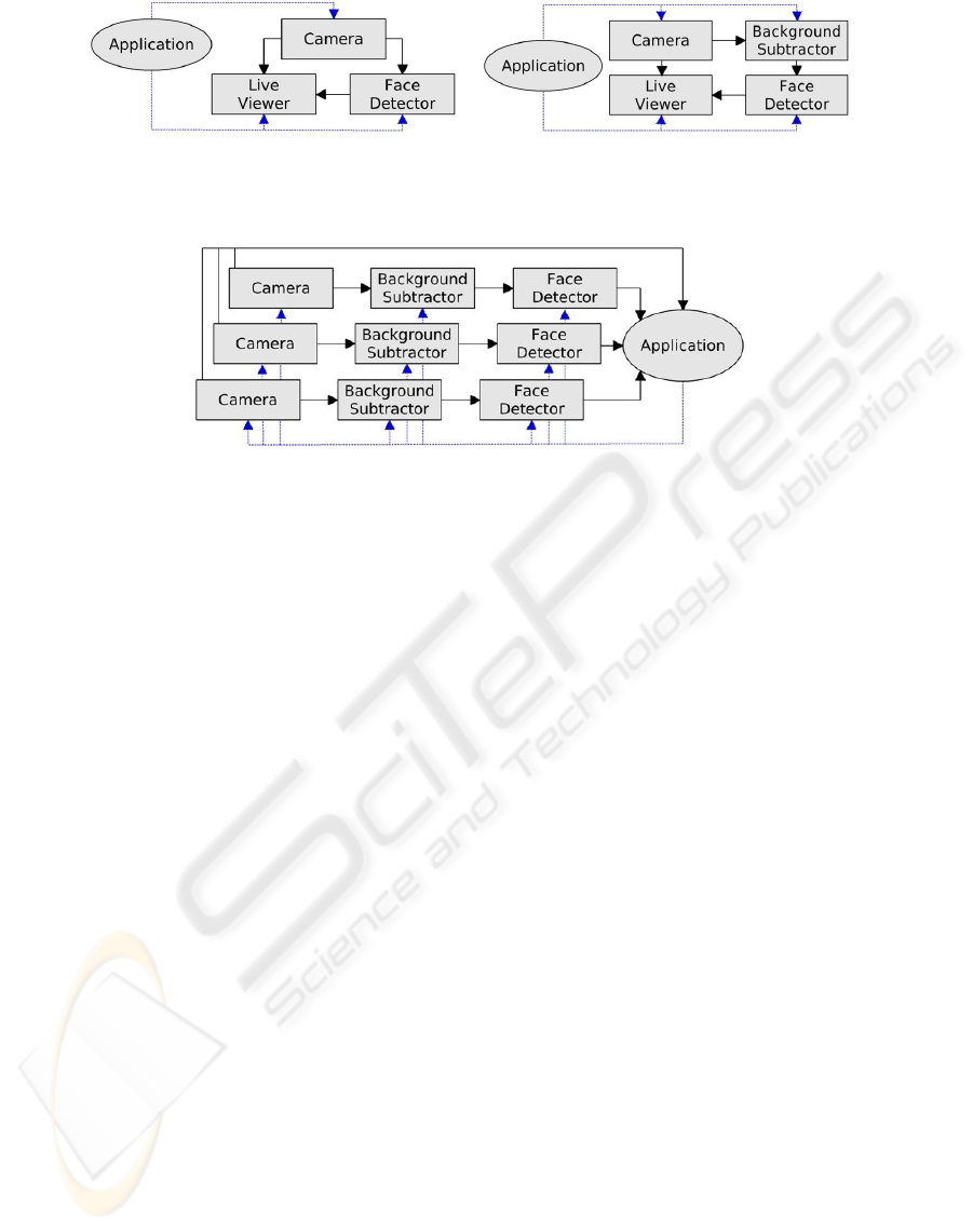
(a) System 1 (b) System 2
Figure 1: Face Detection. Flow charts showing the connections in (a) direct detection and (b) the addition of a Background
Subtractor drone.
Figure 2: Quality of View Analysis. The flow chart for the Hive sensor network for analysing the quality of views via face
detection.
base set of drones, system prototypes can be con-
structed quickly, and swarms can be dynamically con-
nected to test different configurations.
4.1 Face Detection
Our first application is a real-time face detection sys-
tem implemented using four of the Hive drones de-
scribed above: the AXIS Camera; the Background
Subtractor; the Face Detector; and the Live Video
Viewer. The system operates in two ways: the first
detects faces on the original camera images; the sec-
ond performs face detection on a foreground extracted
image. Results demonstrate the improvement in accu-
racy and performance by incorporating a background
subtraction system, and the system itself shows the
simplicity and flexibility of constructing applications
in Hive.
Both methods of face detection use a ‘dumb’ ap-
plication to connect the various drones together. The
application is termed ‘dumb’ because it does not need
to do any computation or result collation itself, as the
drones perform all the processing.
The first method uses the application to connect an
AXIS Camera to both the Face Detector and the Live
Video Viewer, and then connects the Face Detector
to the Live Video Viewer (as shown in Figure 1(a)).
Using Hive and the pre-defined drones, this amounts
to under thirty lines of code (including configuration
parameters). To obtain real-time performance the face
detector is configured to be less accurate and faster,
however this results in more false positives.
For the second system a background subtractor
is inserted between the AXIS Camera and the Face
Detector in order to reduce the number of false pos-
itives while maintaining real-time performance. This
new system, shown in Figure 1(b), removes identified
faces from the background (such as photographs) as
well as reducing the number of false positives. An
evaluation of the face detection systems is presented
in Section 5.1. The addition of the Background Sub-
tractor drone to the system is simple and shows how
systems can be enhanced or tested by inserting addi-
tional processes using Hive.
4.2 Quality of View Analysis
The next application extends the previous real-time
Face Detection algorithm to create a system which
analyses the quality of the given views in a multi-
ple camera network. The quality evaluation is set
to be the number of faces in each view, and the ap-
plication automatically switches to the view with the
most faces. This system could for example be used
for home video podcasting in one-person shows: us-
ing multiple webcams the system will automatically
change to the view the presenter is looking at.
The system connections are shown in Figure 2:
three AXIS Camera drones are each connected to
a Background Subtractor drone which is in turn at-
tached to a Face Detector drone. The cameras are also
connected to the application to provide the images for
the chosen view. As the feeds come in from the Face
Detectors, the number of faces in each view is com-
pared and the view with the most faces chosen, and
its images are routed to the applications display. This
VISAPP 2009 - International Conference on Computer Vision Theory and Applications
104
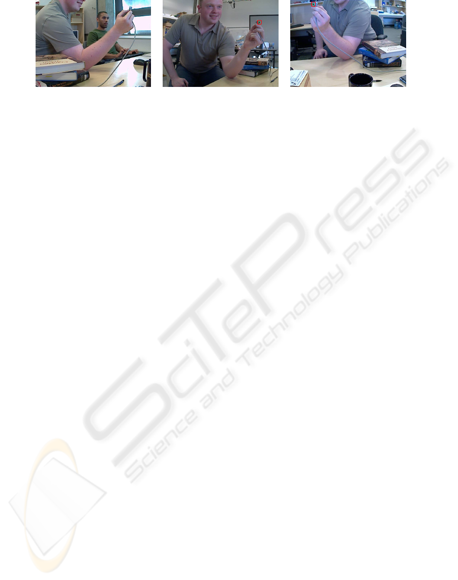
Figure 3: Multiple Camera Calibration. Feed from cameras 1, 2 and 3 during data point collection for calibration.
example application shows how a sophisticated sys-
tem can be built quickly using Hive from a set of base
drones.
Results and an example of the system running are
shown in Section 5.2.
4.3 Multiple Camera Calibration
Our next application is a multiple camera calibration
tool using magnetic sensors to obtain the intrinsic and
extrinsic camera parameters. There are various meth-
ods for computing camera calibration; we have devel-
oped a multiple camera calibration system based on
the Tsai calibration method(Tsai, 1987).
Using Hive we utilize the Colour Point Detector
and the Fastrak drones. For this application we use a
green marker on the Fastrak sensor to locate it in the
image giving an image point to 3D point correspon-
dence. To perform calibration, the marked sensor is
moved around in the field of view of each camera to
produce a data set which is then processed using the
Tsai method to calculate the intrinsic and extrinsic pa-
rameters.
Figure 4(a) shows the interconnection of drones
in the multi-camera calibration system. The appli-
cation is connected to one Fastrak and three sets of
the Colour Point Detector and AXIS Camera swarms.
The application couples the 3D sensor position from
the Fastrak drone with the 2D location of the colour
point from the Colour Point Detector drone and runs
the calibration routine. The resulting calibration pa-
rameters are written to disk for each camera. Figure 3
shows the annotated images for each camera. Note
that extension to more cameras is trivial, requiring an
additional swarm for each camera.
4.4 Augmented Reality
Insertion of virtual objects into a real scene has many
applications in entertainment, virtual reality and hu-
man computer interaction. We have implemented a
real-time augmented reality system using the Fastrak
and multiple cameras that provide jitter-free virtual
object insertion that is accurately represented in the
different camera viewpoints. Figure 4(b) shows the
interconnection of drones for this application. We use
the multiple camera calibration application described
above to calibrate the cameras to the Fastrak’s coordi-
nate system. The calibration data is used to construct
a model of the cameras in OpenGL.
Given this model, a 3D object can be placed in
the scene using the correct position and orientation
supplied by the Fastrak sensor, and rendered in the
image plane of the modelled camera. This rendering
is superimposed on the actual camera feed to produce
the images that contain the virtual object. Figure 5
shows the frames from the three cameras before and
after the placement of the augmented reality object.
5 RESULTS
This section presents the results of the Face Detector
and Quality of View Analysis applications described
above. Results were generated on a 2.33GHz Intel
Core2 Duo with 1GB RAM, with drones running on
a single machine.
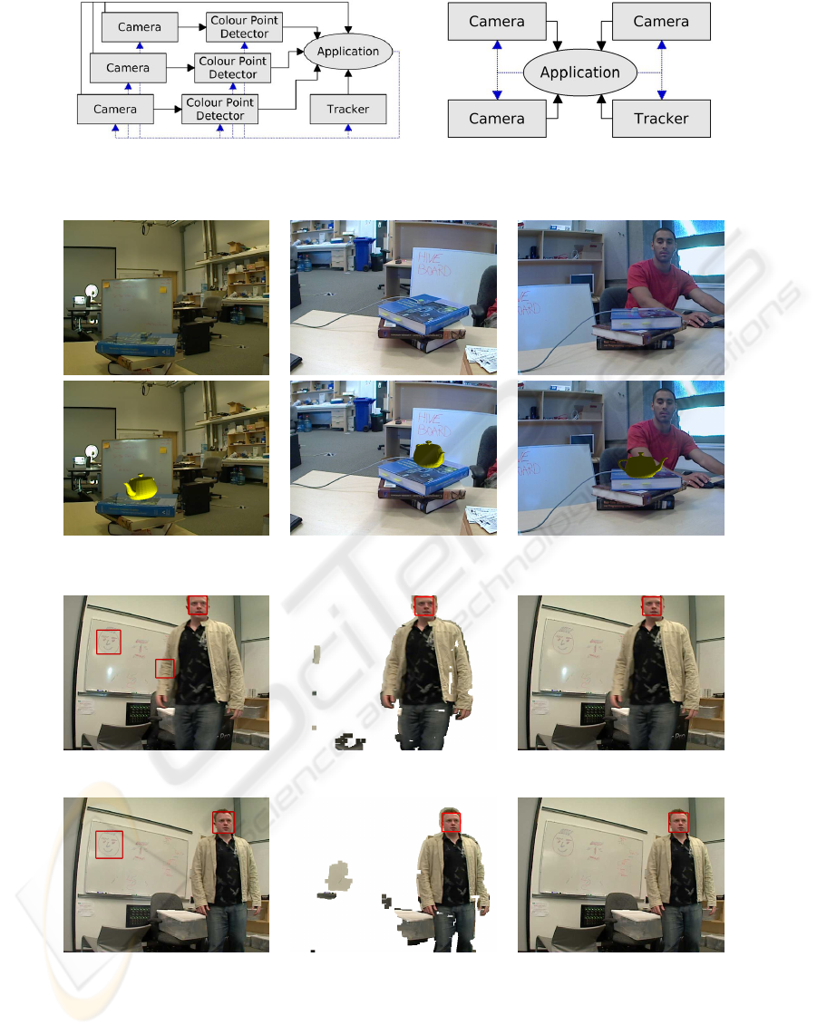
5.1 Face Detection
The Face Detection application described in Sec-
tion 4.1 uses three drones for the first system (di-
rect face detection) and four for the second (including
background subtraction). The results of the two sys-
tems are shown in Figure 6, with and without back-
ground subtraction, and at two levels of accuracy. To
obtain real-time performance the Face Detector is set
to find faces with low accuracy, which increases the
rate of false positives (shown in Figure 6(a)). Attach-
ing a Background Subtractor to the system removes
large regions of the image (Figure 6(b)) where false
positives can appear, as well as removing static faces
(such as photographs) from the scene. Figure 6(c)
shows the final result using the second system. The
second row of images displays results for the system
with the Face Detector in high accuracy mode.
The table in Figure 7 shows the results of the two
systems running on a set of 200 frames in a clut-
RAPID VISION APPLICATION DEVELOPMENT USING HIVE - A Modular and Scaleable Approach to Vision System
Engineering
105
(a) (b)
Figure 4: Drone connections for (a) Multiple Camera Calibration, (b) Augmented Reality.
Figure 5: Augmented Reality. Original feed from the cameras vs. Augmented Reality.
(a) (b) (c)
Fast detection Foreground image Result from (b) overlaid
(d) (e) (f)
Accurate detection Foreground image Result from (e) overlaid
Figure 6: Face Detection. (a)-(c) show the results of the fast method, (d)-(f) the accurate method; both show improvement
through the addition of background subtraction.
tered scene, in both low and high accuracy modes.
The fast mode (low accuracy) with background sub-
traction provides improvements in false positives and
positive matches, with only a slight dip in processing
speed. The background subtraction also removes the
static faces in the scene.
VISAPP 2009 - International Conference on Computer Vision Theory and Applications
106
Mode False Positives Background Faces Positive Matches FPS
Fast 3% 91% 92.4% 15.3
Fast + BGS 1% 0% 95.1% 13.1
Accurate 3.5% 85.5% 98.4% 3.9
Accurate + BGS 0% 0% 98.9% 6.4
Figure 7: Face Detection. Results of the face detection on a 200 frame sequence.
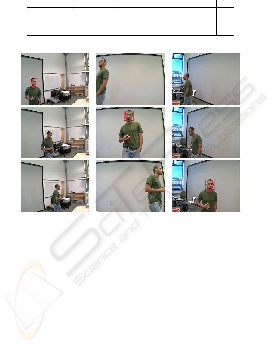
Figure 8: Quality of View Analysis. Each row represents a snapshot in time from each of the three cameras. The red boxes
in the top-left, centre and bottom-right images show positive detections and the view chosen by the system.
The slow mode (high accuracy) actually had the
most false positives but a higher rate of positive
match. When combined with background subtraction
it became the best overall system, with zero false pos-
itives, zero static faces and the highest rate of positive
match. The background subtraction also increased the
frame rate (since the search for faces did not need to
work at multiple scales on background regions).
These results demonstrate the systems built using
Hive are flexible and capable of performing in real-
time.
5.2 Quality of View Analysis
Figure 8 shows the results of the Quality of View
Analysis application. The system was tested on three
cameras converging on a single region, in a varied
scene. Each row represents a snapshot in time from
each of the three cameras. View switching occurs
when a face is identified, shown as the red rectangle
in the top-left, centre, and bottom-right images. The
system operates in real-time, and is easily scalable us-
ing Hive to support many more cameras.
5.3 Performance
The drones used in our system all perform at real-time
rates, as shown in the table in Figure 9. The Back-
ground Subtractor and Colour Point Detector have
not been optimized and their frame rate could be im-
proved. While the rate of the applications is shown at
less than the camera rate, all applications display the
camera images at close to 30Hz, and use the results of
the other drones to update the system, which happens
less frequently.
RAPID VISION APPLICATION DEVELOPMENT USING HIVE - A Modular and Scaleable Approach to Vision System
Engineering
107
Drone Rate
AXIS Camera 29.5fps
Background Subtractor 15fps
FasTrack 120Hz
Face Detector 13fps
Colour Point Detector 20fps
Application Rate
Face Detection 15fps
Face Detection (BGS) 13fps
QoV Analysis 13fps
Augmented Reality 27fps
Figure 9: Performance. These tables document the performance of the drones individually and of the applications.
6 CONCLUSIONS
We have presented a novel method for creating sensor
fusion networks using Hive. The systems consisted
of multiple sensors, from input devices such as cam-
eras and 3D trackers, to processing systems such as
background subtraction and face detection. As proof
of concept four applications were described, for face
detection, quality of view analysis, multiple camera
calibration from 3D sensor, and augmented reality in
multiple cameras. The set of drones used to create
these applications have been described, as well as the
simple process of integrating new functionality as a
drone. Results have demonstrated the flexible con-
struction and the ability to prototype systems quickly
using Hive, and the real-time performance achieved.
We have many other drones either implemented
or under development, such as a Tri-Stereo Camera,
Symbian OS and iPhone drones (for visualization on
mobile phones, and the use of camera phones), Hand
Tracker and Eye Tracker, to name a few.
Hive has been released for use by the vision and
robotics communities, as well as a number of drone
implementations. Visit:
http://hct.ece.ubc.ca/research/Hive/
for details.
REFERENCES
Afrah, A., Miller, G., Parks, D., Finke, M., and Fels, S.
(2008). Hive: A distributed system for vision process-
ing. In Proc. 2nd International Conference on Dis-
tributed Smart Cameras.
Bradski, G. and Kaehler, A. (2008). Learning OpenCV:
Computer Vision with the OpenCV Library. O’Reilly
Media, Inc., 1st edition.
Gerkey, B., Vaughan, R., Stoy, K., Howard, A., Sukhatme,
G., and Mataric, M. (2001). Most valuable player: a
robot device server for distributed control. In Intel-
ligent Robots and Systems, 2001. Proceedings. 2001
IEEE/RSJ International Conference on, pages 1226–
1231.
Lienhart, R. and Maydt, J. (2002). An extended set of haar-
like features for rapid object detection. In Proceed-
ings of International Conference on Image Process-
ing, volume 1, pages 900–903.
Luo, R. C., Chin-Chen, Y., and Kuo, L. S. (2002). Multisen-
sor fusion and integration: approaches, applications
and future research directions. IEEE Sensors Journal,
2:107–119.
Metta, G., Fitzpatrick, P., and Natale, L. (2006). Yarp: yet
another robot platform. In International Journal of
Advanced Robotics Systems.
Polhemus (2008). Fastrak :
http://www.polhemus.com/. Technical report.
Schimek, M. H., Dirks, B., Verkuil, H., and
Rubli, M. (2008). Video for linux v4.12:
http://v4l2spec.bytesex.org/v4l2spec/v4l2.pdf.
Technical Report 0.24, Linux.
Tsai, R. (1987). A versatile camera calibration technique for
high-accuracy 3d machine vision metrology using off-
the-shelf tv cameras and lenses. Robotics and Automa-
tion, IEEE Journal of [legacy, pre - 1988], 3:323–344.
VAPIX (2008). Axis communication api:
http://www.axis.com. Technical report, AXIS.
VISAPP 2009 - International Conference on Computer Vision Theory and Applications
108
