SKELETON-BASED RIGID SKINNING
FOR CHARACTER ANIMATION
Andreas Vasilakis and Ioannis Fudos
Department of Computer Science, University of Ioannina, Ioannina, Greece
Keywords:
Skeletonization, Rigid skinnig, Character animation, Mesh generation.
Abstract:
Skeleton-based skinning is widely used for realistic animation of complex characters defining mesh move-
ment as a function of the underlying skeleton. In this paper, we propose a new robust skeletal animation
framework for 3D articulated models. The contribution of this work is twofold. First, we present refinement
techniques for improving skeletal representation based on local characteristics which are extracted using cen-
troids and principal axes of the character’s components. Then, we use rigid skinning deformations to achieve
realistic motion avoiding vertex weights. A novel method eliminates the artifacts caused by self-intersections,
providing sufficiently smooth skin deformation.
1 INTRODUCTION
In video games, crowd simulations, computer gener-
ated imagery films and other applications of 3D com-
puter graphics, achieving skin motion of deformable
objects in a realistic-looking way is of utmost impor-
tance. Since, due to its versatility, skeletal animation
is one of the most popular techniques, we focus on
skin motion techniques for skeletal animation of ar-
ticulated objects.
In skeletal animation, a representation model con-
sists of at least two main layers: a highly detailed 3D
surface representing the character’s skin, and an un-
derlying skeleton which is a hierarchical tree structure
of joints connected with rigid links (bones) providing
a kinematic model of the character.
The process of extracting a skeleton is called
skeletonization. A skeleton acts as a special type of
deformer transferring its motion to the skin by as-
signing each skin vertex one (rigid skinning) or more
(linear blending skinning-LBS) joints as drivers. In
the former case, inherent flaws arise caused by self-
intersections, especially in areas around joints. In the
latter case of LBS , each skin vertex is assigned mul-
tiple influences and blending weights for each joint.
This scheme provides more detailed control over the
results. However, the generated meshes exhibit vol-
ume loss as joints are rotated to extreme angles pro-
ducing non-natural deformations (also known as col-
lapsing joint and candy wrapper effects). Yet an-
other problem with LBS is that tuning the LBS ver-
tex weights tends to be a tedious and cumbersome
task (Lewis et al., 2000; Mohr and Gleicher, 2003;
James and Twigg, 2005). Despite these drawbacks,
variations of this method are widely used in interac-
tive computer graphics applications because they are
simple and easy to implement on GPUs.
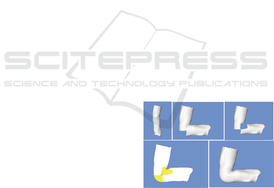
Figure 1: Robust rigid skinning. From top left to bottom
right: the initial model; rotating the lower part; removing
points; adding points; construct a robust blending patch.
To address the above issues we present an integrated
skeleton-based rigid skinning framework for animat-
ing 3D solid modular articulated models. A visu-
ally satisfactory skeleton is extracted using centroids
and principal axes (Lien et al., 2006) of the compo-
302
Vasilakis A. and Fudos I.
SKELETON-BASED RIGID SKINNING FOR CHARACTER ANIMATION.
DOI: 10.5220/0001799803020308
In Proceedings of the Fourth International Conference on Computer Graphics Theory and Applications (VISIGRAPP 2009), page
ISBN: 978-989-8111-67-8
Copyright
c
2009 by SCITEPRESS – Science and Technology Publications, Lda. All rights reserved

nents of a segmented object by performing a depth-
first traversal of the skeleton hierarchy tree. We re-
fine the produced skeleton segments with local and
neighbor features to derive better skeletal represen-
tations that are more appropriate for our application.
Then, we use classic rigid skinning by assigning each
skin vertex to an influence bone to achieve mesh an-
imation avoiding thus vertex weight estimation and
training pose set production costs. We introduce a
novel method to eliminate degeneracies and artifacts
from self-intersections, especially in areas near joints,
by performing alternative intuitive deformations. Fig-
ure 1 illustrates the entire process.
2 RELATED WORK
There is an abundance of research work in the litera-
ture that tackles the skeleton extraction and skinning
of 3D objects from different perspectives. We focus
on recent developments most closely related to ani-
mation.
Skeletonization algorithms may be classified
based on whether they work on the boundary surface
(geometric methods) or on the inner volume (volumet-
ric methods). Researchers have proposed geometric
based algorithms approximating MAT to overcome
some of its inefficiencies, however MAT based skele-
tons are still not well fitted for animation applications.
Several methods (Liu et al., 2003; Ma et al., 2003)
generate skeletons by constructing discrete field func-
tions by means of the object’s volume. Although ac-
curate, such methods are usually very time consuming
and they cannot be applied to animation since the vol-
umetric information needed is not usually part of the
animation model. Researchers also generate skeletons
based on mesh contraction (Au et al., 2008). (Katz
and Tal, 2003) extract a skeleton using a hierarchical
mesh decomposition algorithm. Finally, (Lien et al.,
2006) proposed an iterative approach that simultane-
ously generates hierarchical shape decomposition and
a corresponding set of multi-resolution skeletons.
Linear blend skinning (LBS) is the most widely
used technique for real-time animation due to its com-
putational efficiency and straightforward GPU imple-
mentation (Rhee et al., 2006). Recent skinning al-
gorithms are classified based on whether they use
(Geometric methods) or a training set of poses (Ex-
ample based methods) of input models. Geometric
methods revert to non-linear blending of rigid trans-
formations since deformation is inherently spherical.
Numerous proposed methods have replaced the lin-
ear blending domain with simple quaternion (Hejl,
2004), spherical blending (Kavan and
ˇ
Z´ara, 2005) and
dual quaternion (Kavan et al., 2008). Example-based
methods remove artifacts by correcting LBS errors
with storage and computation cost increase (Lewis
et al., 2000; Wang and Phillips, 2002; Merry et al.,
2006). Our rigid skinning approach falls under Geo-
metric class of algorithms introducing a novel versa-
tile, robust and efficient blending approach based on
rational quadratic Bezier patches.
3 SKELETONIZATION
We have built on techniques introduced by (Lien
et al., 2006) that produce refined local skeletal morphs
from the components of modular models. A straight-
forward approach to build the skeleton of a compo-
nent is to connect the opening centroids. A boundary
of a componentconsists of the common joining points
of two adjacent components generated during a mesh
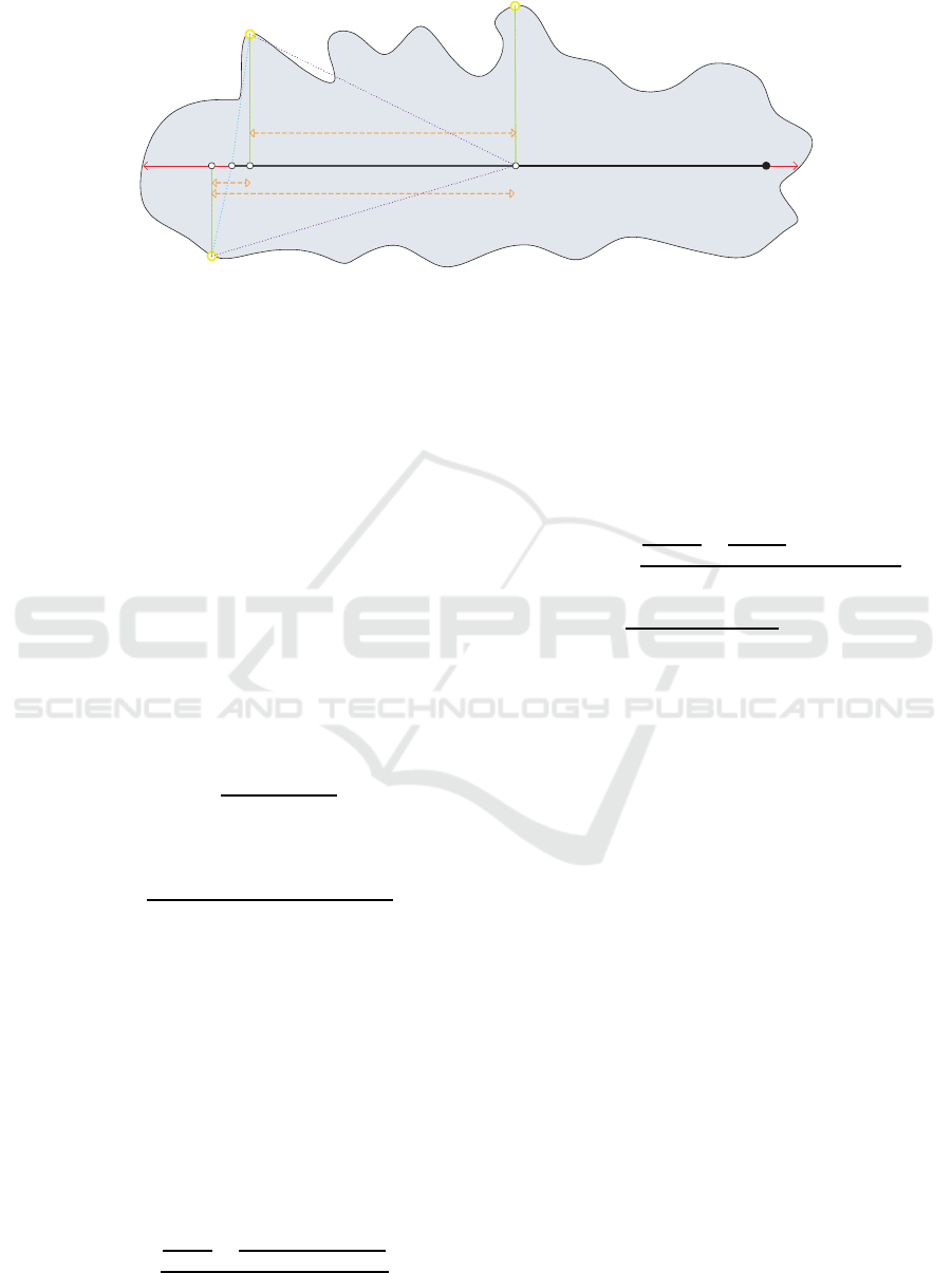
segmentation process. We denote the centroid of a
boundary as opening centroid. An improvement over
this method is to use the centroid or kernel centroid of
the component in addition to the opening centroids.
However, frequently they do not capture the compo-
nent shape accurately.
In (Lien et al., 2006) proposed to overcome failures
of previous methods by extracting a skeleton from
a component by connecting the opening centroids to
the principal axis. Our approach adapts this skeleton
extraction technique for use in our animation frame-
work. Let OC be the set of the opening centroids
oc
i
of component C, OC = {oc
1
,... , oc
n
}. First, we
select the principal axis segment of the component’s
convexhull that resides within the interior of the com-
ponent. For even better results we have used as major
axis an axis parallel to the principal axis of the con-
vex hull that goes through the kernel centroid of the
component to ensure that skeleton segments have the
least possible intersection with the component’s bor-
der. We denote this major axis segment as pa. We
subdivide the pa in a number of uneven segments by
picking as link points the projections of the opening
centroids on pa (see Figure 2). Let P
pa
(oc
i
) be the
projection of opening centroid oc
i
on pa. Our match-
ing algorithm uses a dynamic programming concept,
enhanced with new score functions which aim at max-
imizing the length of the utilized pa.
After grouping has been performed, we create
the set of skeleton edges. Beyond the standard con-
nections between the opening centroids and the link
points, we use extra skeleton edges based on the map-
ping result.
Our approach improves the principal axis orien-
tation by introducing two modifications, the first is
SKELETON-BASED RIGID SKINNING FOR CHARACTER ANIMATION
303
oc
2
oc
1
oc
3
pa
P
pa
(oc
1
) P
pa
(oc
2
)
L
pa
(oc
12
)
d
min
(oc
2
)
d
min
(oc
1
)
d
m
a
x
(
o
c
2
)
d
m
a
x
(
o
c
1
)
d
(
o
c
1
,
L
p
a
)
d
(
o
c
2
,
L
p
a
)
P
pa
(oc
3
)
d(P
pa
(oc
1
),P
pa
(oc
2
))
d(P
pa
(oc
1
),P
pa
(oc
3
))
d(P
pa
(oc
2
),P
pa
(oc
3
))
sk
gr
sk
con
Figure 2: Skeleton segments extracted by the grouping (sk
gr
) and the connecting (sk
con
) algorithm.
based on local features and the second uses knowl-
edge inherited from the component hierarchy. Finally,
we propose to add four more joints which represent
the two ends of the other axes segments making the
skeletal representation more topologically expressive.
3.1 Grouping Algorithm
Our approach manages to minimize the total mapping
length and the cardinality of the set of link points
(score function F
1
), while at the same time maximizes
the used pa length (score function F
2
).
Let d(~p
1
, ~p
2
) be the euclidean distance between
point ~p
1
and point ~p
2
. For a set of opening cen-
troids, oc
ij
= hoc
i
,... , oc
j
i, we compute their link
points on pa as the average of their projections by
L
pa
(oc
ij
) =
∑
j
k=i
P
pa
(oc
k
)
|oc
ij
|
(1)
∀ oc
k
∈ oc
ij
, we evaluate its normalized variation as
V(oc
k
) =
d(oc
k
,L
pa
(oc
ij
)) − d
min
(oc
k
)
d
max
(oc
k
) − d
min
(oc
k
)
(2)
where d
min
(oc
k
) = d(oc
k
,P
pa
(oc
k
)) and
d
max
(oc
k
) = max
1≤l≤|OC|
{d(oc
k
,oc
l
)}.
Moreover, we define the ratio of the pa length
which is vanished after grouping as the pa length
which is generated among the projections of these
opening centroids divided by the maximum used pa
length.
Definition 1. The normalized merging score function
F
1
for oc
ij
group set is defined as the average of the
total distance cost and the ratio of the not used pa
length,
F
1
(oc
ij
) =
∑
j
k=i
V
k
|oc
ij
|
+
d(P
pa
(oc
i
),P
pa
(oc
j
))
d(P
pa
(oc
1
),P
pa
(|OC|))
2
(3)
Definition 2. The normalized separating score func-
tion F
2
for groups G
x
= hoc
x
i
,... , oc
x
l
i and G
y
=
hoc
y
l+1
,... , oc
y
j
i is defined as the average of the sums
of their total distance cost and the complement of the
ratio of pa length which is generated between these
groups,
F
2
(G
x
,G
y
) =
∑
V(oc
x
k
)
|G
x
|
+
∑
V(oc
y
k
)
|G
y
|
+ (1− gR
pa
)
3
(4)
where gR
pa
=
d(P
pa
(oc
x
l
),P
pa
(oc
y
l+1
))
d(P
pa
(oc
1
),P
pa
(|OC|))
.
3.2 Connecting Algorithm
The final skeleton of the component contains line seg-
ments that connect opening centroids to link points
and line segments that interconnect link points. Open-
ing centroid grouping often generates skeletons that
do not capture important topological information.
Therefore, the connection algorithm works with the
following rules:
1. If all opening centroids are grouped to one link
point and this point is close to:
• pa’s centroid, we connect it with the pa’s end points
on both sides of its centroid.
• one of pa’s end points, we connect it with the pa’s
end point on the other side of pa’s centroid.
2. If opening centroids are connecting to more than
one link point and these points are close to:
• pa’s centroid, we connect the first and the last link
points with the pa’s end points on both sides of pa’s
centroid, respectively.
• one of pa’s end points, we connect the first or the last
link point with the pa’s end point on the other side
of pa’s centroid.
GRAPP 2009 - International Conference on Computer Graphics Theory and Applications
304
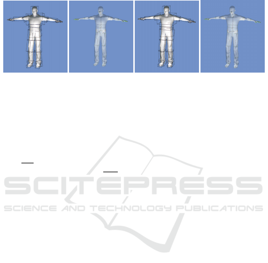
Figure 3: Oriented bounding boxes and skeletons of “Human” components: (left) Original configuration (right) After align-
ment.
3.3 Local Refinement
To achieve optimal or satisfactory orientation results,
we approximately align principal directions along
some qualitative features through slight modification.
The proposed algorithm performs weighted vector
alignment for each opening centroid. If the com-
ponent has more than one opening centroids, we
align with regards to the closest principal direction by
angle=
α
weight
, where α is the angle between the given
vector and its closest axis and weight w =
1
|OC|+1
ex-
cept from the opening centroid which lies at the root.
This is assigned an increased weight : 2∗ w, such that
∑
|OC|
i=1
w
i
= 1.
3.4 Hierarchical Refinement
We extend the orientation improvements performed
individually on each component by performing opti-
mal fitting of the local principal directions of neigh-
bor components. The algorithm starts from the chil-
dren of the root node of the skeleton tree perform-
ing the same process to their children until it reaches
the tree leaves. For each component, this process first
aligns with regards to the parent’s principal direction
which is closer to the child’s principal axis. Subse-
quently, from the rest of the child’s and parent’s prin-
cipal directions we detect those that are closer and
aligns them. Note that fitting two principal direc-
tions from different components, results in rotating
the other principal directions too.
4 ADVANCED RIGID SKINNING
We have developed a novel technique to address the
major flaws from self-intersections in areas around
the joints providing sufficiently smooth skin defor-
mation. Briefly, our approach first removes the skin
vertices of the overlapping component parts and then
adds new vertices to fill in the gap. Finally, for each
frame it constructs a blending mesh that produces a
smooth surface using a robust triangulation method.
4.1 Removing Vertices
The first step of our technique is to detect which ver-
tices from each of the collided components are lo-
cated inside each other. A fast approximate test is to
use the oriented bounding box (OBB) since accurate
methods require a lot of computational resources. We
start from the boundary points to perform the fewer
tests since they have the highest probability to be in-
side the other component’s OBB and move through
their 1-ring of neighbors until we reach the points
which are in the outer side of the OBB. Two points
are 1-ring neighbors if they belong to the same facet.
4.2 Adding Vertices
Definition 3. There are three point sets that will use
to construct the blending mesh:
• Boundary is the set of boundary points that have not
been removed.
• Replaced is the point set that will replace the points that
have been removed.
• In-between is the point set which consists of the average
of the initial and final positions of the opening points
which have been removed (O
i,initial
,O
i
points).
We present two blending techniques; the first one
called front blending patch construction uses only
the Boundary set and the second called rear blend-
ing patch construction uses both the Replaced and In-
between sets.
4.2.1 Front Blending Patch Construction - Fbps
The observation behind this process is that when we
rotate a component about an arbitrary axis, movement
SKELETON-BASED RIGID SKINNING FOR CHARACTER ANIMATION
305
of every point B ∈ Boundary will describe a circu-
lar arc. The task is to find new points by interpolat-
ing from the point’s position (B
0
= q
0
Bq
−1
0
) before
the rotation q
0
to the point’s position after rotation
(B
′
0
= q
1
Bq
−1
1
) q
1
(see Figure 4). We use fast linear
interpolation of quaternions (QLERP) since the inter-
polation along the shortest segment hardly causes any
observable skin defect (Kavan and
ˇ
Z´ara, 2005).
4.2.2 Rear Blending Patch Construction - Rbps
We have to fill in the gap in the area where we have
removed points from both components. The major
issue is that we only have the Replaced points from
each component without any correspondence between
them. So, we propose to use as extra point set,
called In-between points.
A grouping function is developed to create triplets
from each InB
i
∈ In-between and one point from
child’s and parent’s Replaced sets (R
C
j
,R
P
k
points, re-
spectively). The feature of each triplet is that the
plane defined by its points, has the minimum dihe-
dral angle with the plane defined by the joint position
and the kernel centroids of the participating compo-
nents (plane PL). Then, we construct blending arcs
given the triplet as control points using a Rational
Bezier representation (Fudos and Hoffmann, 1996).
The tangent vectors at R
C
j
,R
P
k
defined as the projec-
tions on PL of the vectors going from the joint posi-
tion to child’s and parent’s kernel centroids, respec-
tively. To prevent the generated meshes from exhibit-
ing volume loss as joints rotate to extreme angles we
replace InB
i
point with V
m
. We define V
m
as the aver-
age of the InB
i
point and the intersection of their tan-
gents (I
p
) and then evaluate the tangents (T
C
,T
P
) to
the vectors going from R
C
j
,R
P
k
to InB
i
(see Figure 4).
4.3 Blending Mesh
The points derived through the two blending pro-
cesses constitute the scattered 3D data which will
be triangulated. In this work, we use the Tight Co-
cone (Dey and Goswami, 2003) algorithm to con-
struct water-tight surfaces. Since we need only two
parts of the generated spheroid to fill the holes, we
must eliminate a number of unnecessary facets to de-
rive optimal lighting results. The evaluation of the
patch point normal vectors is achieved by averaging
the normals of the output surface facets and the nor-
mals of the pre-existant component facets that share
the point.
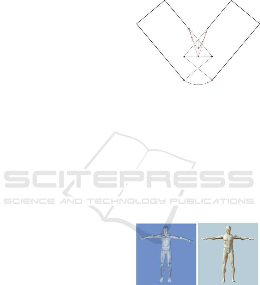
O
i,initial
O
i
i
V
m
InB
B
0
B’
0
IP
FBPC
R
j
R
k
T
C
T
P
P
C
RBPC
Figure 4: Introducing additional points and blending curves.
5 COMPLEXITY AND
PERFORMANCE EVALUATION
The input to our framework is a segmented poly-
hedron model and its associated skeleton hierar-
chy information. At the following experiments we
decompose characters into components using the
Blender (http://www.blender.org/) software. A sum-
mary of the characteristing studied models (courtesy
of (efrontier, 2006; AIM@SHAPE, 2008)) is given in
Table 1.
We evaluate our proposed algorithms with respect
to two criteria: quality and performance. All tests
were performed on an 2.4 GHz Intel Core Quad with
2GB of RAM.
Figure 5: Comparison on a human model between our re-
fined skeleton and a default hand-made skeleton.
Table 1 provides computation times for extracting
skeletons from the above models. Most of the time
is due to the principal directions and kernels centroid
computation which is performed in
∑
k
i=0
O(n
i
logn
i
)
and
∑
k
i=0
O(n
i
logn
i
) + O(r
i
logr
i
) time respectively,
for a character with k components where the ith com-
ponent has n
i
vertices and r
i
kernel points. The local
and hierarchical refinement methods times are negli-
GRAPP 2009 - International Conference on Computer Graphics Theory and Applications
306
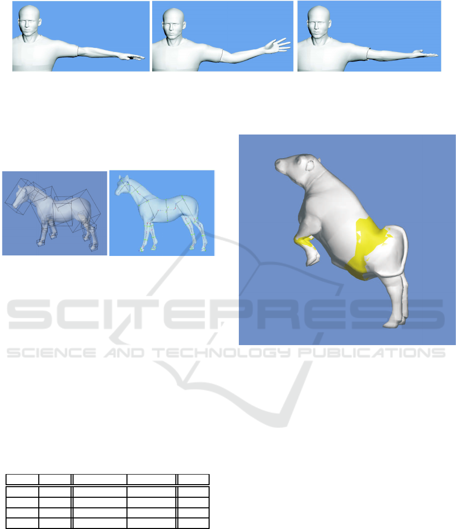
Figure 6: Avoidance of the typical LBS “candy-wrapper” artifact. (Left) is a reference pose, (middle) upper arm is rotated
90
o
about its axis, and on (right) upper arm is rotated 180
o
about its axis.
gible compared to the overall performance. However,
we observe from measures of Table 1 that skeleton ex-
traction complexity appear to be nearly linear on the
number of triangles.
Figure 7: Refined oriented bounding boxes and skeletons of
the components of a horse model.
It’s difficult to compare our method with other re-
cent methods, since the input model should be seg-
mented. Figure 3 illustrates the qualitative superior-
ity of our refined skeletons and aligned OBBs over
the original principal axis algorithm. In general, our
method generates refined skeletons in less than half a
minute for dense models (Figures 3, 5, 7). Thus, if our
method is used in conjunction with a fast decomposi-
tion method, it will be a very efficient overall process.
Figure 5 illustrates the similarity between the default
skeleton generated by Poser software and a skeleton
extracted by our method.
Table 1: Experimental models and performance of their
skeletonization steps (time measured in seconds).
Model Vertices Kernel Centroid Principal Axis Total
Cow 3825 1.982 0.868 2.995
Horse 8964 2.086 0.924 3.178
Dilo 26214 4.701 2.022 7.150
Human 74014 10.244 4.649 14.893
We create animations by re-targeting hand-made mo-
tion data to the skeletons extracted from the original
meshes. Figures 6 and 8 show animated poses us-
ing our rigid skinning technique. We also provide
snapshots depicting a closer view of a human knee
mesh to demonstrate the robustness of the skinning
process (Figure 1). These visual results confirm that
our method is indeed free of artifacts exhibited by pre-
vious LBS methods working only on a single mesh.
Figure 8: Cow multiple part animation. Patched parts are
highlighted in yellow.
However, the overall processing time of our skin-
ning method is very high for a real-time animation
due to the computation of new points which takes
O(n
1
· n
2
· n
3
) time to complete ( n
1
and n
2
are the
numbers of Replaced points of moving and its parent
components and n
3
is the cardinality of In-between
set) and the triangulation algorithm O(n
2
) complex-
ity, where n is the number of the constructed points.
For instance, Table 2 shows the time performance of
our rigid skinning animating figure’s 1 human’s knee
from initial pose to extreme angles where moving and
its parent components consist of 891 and 1000 ver-
tices, respectively.
6 CONCLUSIONS AND FUTURE
WORK
We have proposed a robust skeleton-based animation
framework for 3D characters. Approximate refine-
ment algorithms have been presented to improve ex-
SKELETON-BASED RIGID SKINNING FOR CHARACTER ANIMATION
307
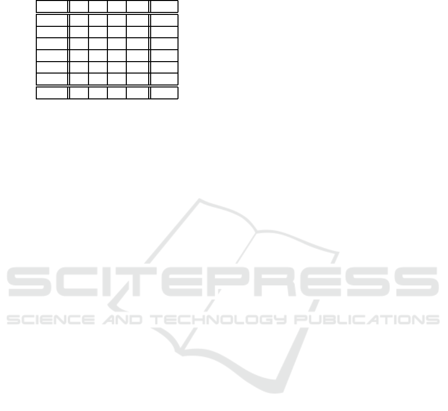
Table 2: Rigid skinning performance of human’s knee ani-
mation (time measured in seconds).
Frame n
1
n
2
n
3
n Time
1 26 28 24 64 0.390
2 27 28 23 93 0.421
3 26 31 22 116 0.456
4 27 32 23 150 0.510
5 28 34 24 188 0.572
6 35 37 24 214 0.654
Mean 28 32 23 137 0.501
tracted skeleton’s orientation. We have developed a
novel rigid skinning method that eliminates the po-
tential shortcomings from self-intersections, provid-
ing plausible mesh deformations.
Considering completeness there is need for fur-
ther investigating in a more quantitative manner the
grouping functions. Further, one could try replac-
ing the angle-weighted algorithm with an optimiza-
tion method which will compute the principal axis
orientation more accurately.
Finally, to achieve real-time animation an alterna-
tive triangulation method should be employed and its
GPU realization should be investigated.
REFERENCES
AIM@SHAPE (2008). http://shapes.aim-at-
shape.net/.
Au, O. K.-C., Tai, C.-L., Chu, H.-K., Cohen-Or, D.,
and Lee, T.-Y. (2008). Skeleton extraction by
mesh contraction. ACM Trans. Graph., 27(3):1–
10.
Dey, T. K. and Goswami, S. (2003). Tight cocone:
a water-tight surface reconstructor. In ACM SM
’03, pages 127–134.
efrontier (2006). Poser 7.
http://my.smithmicro.com/win/poser/index.html.
Fudos, I. and Hoffmann, C. M. (1996). Constraint-
based parametric conics for CAD. Computer-
aided Design, 28(2):91–100.
Hejl, J. (2004). Hardware skinning with quaternions.
Game Programming Gems, 4:487–495.
James, D. L. and Twigg, C. D. (2005). Skinning
mesh animations. ACM Transactions on Graph-
ics, 24:399–407.
Katz, S. and Tal, A. (2003). Hierarchical mesh de-
composition using fuzzy clustering and cuts. In
ACM SIGGRAPH ’03, pages 954–961.
Kavan, L., Collins, S., Zara, J., and O’Sullivan, C.
(2008). Geometric skinning with approximate
dual quaternion blending. ACM Trans. Graph.,
27(4).
Kavan, L. and
ˇ
Z´ara, J. (2005). Spherical blend
skinning: a real-time deformation of articulated
models. In Proc. of the 2005 symposium on In-
teractive 3D graphics and games, pages 9–16.
ACM.
Lewis, J. P., Cordner, M., and Fong, N. (2000). Pose
space deformation: a unified approach to shape
interpolation and skeleton-driven deformation.
In ACM SIGGRAPH ’00, pages 165–172.
Lien, J.-M., Keyser, J., and Amato, N. M. (2006).
Simultaneous shape decomposition and skele-
tonization. In Proceedings of the 2006 ACM
Symposium on Solid and Physical Modeling,
pages 219–228.
Liu, P.-C., Wu, F.-C., Ma, W.-C., Liang, R.-H., and
Ouhyoung, M. (2003). Automatic animation
skeleton using repulsive force field. Proceed-
ings of the 11th Pacific Conference on Computer
Graphics and Applications, pages 409–413.
Ma, W.-C., Wu, F.-C., and Ouhyoung, M. (2003).
Skeleton extraction of 3d objects with radial ba-
sis functions. In Proceedings of the Shape Mod-
eling International 2003, page 207.
Merry, B., Marais, P., and Gain, J. (2006). Animation
space: A truly linear frameworkfor character an-
imation. ACM Trans. Graph., 25(4):1400–1423.
Mohr, A. and Gleicher, M. (2003). Building efficient,
accurate character skins from examples. ACM
Trans. Graph., 22(3):562–568.
Rhee, T., Lewis, J., and Neumann, U. (2006). Real-
time weighted pose-space deformation on the
GPU. Computer Graphics Forum, 25(3):439–
448.
Wang, X. C. and Phillips, C. (2002). Multi-weight
enveloping: least-squares approximation tech-
niques for skin animation. In Proceedings of the
2002 ACM symposium on Computer animation,
pages 129–138.
GRAPP 2009 - International Conference on Computer Graphics Theory and Applications
308
