
A NOVEL APPROACH TO ACHIEVE ROBUSTNESS AGAINST
MARKER OCCLUSION
Hugo
´
Alvarez, Diego Borro
Centro de Estudios e Investigaciones T´ecnicas de Guip´uzcoa, CEIT, Spain
Keywords:
ARToolkitPlus, Marker tracking, Occlusion.
Abstract:
This paper introduces a novel estimation technique to compute camera translation and rotation (only in the
axis that is perpendicular to the image plane) when a marker is partially occluded. The approach has two main
advantages: 1) only one marker is necessary; and 2) it has a low computational cost. As a result of the second
feature, this proposal is ideal for mobile devices. Our method is implemented in ARToolkitPlus library, but it
could be implemented in another marker-tracking library with square markers. A little extra image processing
is needed, taking advantage of temporal coherence. Results show that user feels enough realistic sensation to
apply this technique in some applications.
1 INTRODUCTION
The objective of the Augmented Reality (AR) is em-
bedding virtual objects into the field of view of the
user. With this statement in mind, the tracking and
registration problem is today one of the most funda-
mental challenges in AR research. To achieve that the
real and the virtual world are properly aligned with
respect to each other, the cameras position within the
environment has to be determined.
The marker-based tracking detects reference ob-
jects (markers), which have been previously placed
manually to the environment. There are different
types of markers, with distinct shapes as circular
(de Ipia et al., 2002) or planar (Zhang et al., 2002), or
based on color-coded (Mohring, 2004); but the most
popular and also public available marker-based track-
ing software is ARToolkit, developed by Hirokazu
Kato et al. (Kato et al., 2000). ARToolkitPlus is an
extended version that adds features and uses different
type of markers(BCH markers) (Wagner and Schmal-
stieg, 2007).
The disadvantages of the marker-based alternative
are the sensitive to the occlusion and the environment
adaptation. (Tateno, 2007; Kato and Billinghurst,
1999; Lee et al., 2004) use multiple markers to solve
the first drawback, but it requires more than one
marker, so it increases the second disadvantage. Our
method improves the robustness with occlusions and
does not incorporate any extra marker.
In the other hand, generally, the vision-based algo-
rithms need too much computing power to be applied
in handheld devices, which processing and mem-
ory capabilities are limited. Due to this reason, our
method is initially ideal for mobile devices, as it uses
the information calculated by ARToolkitPlus, and it
requires a little image analysis.
In Section 3 the communication between our
method and ARToolkitPlus is presented. Then, in
Section 4 our method is explained in detail, and some
experiments are described in Section 5. In this section
some images are also shown to see how our method
works. Finally, in Section 6 conclusion of the whole
work is presented.
2 RELATED WORK
ARTag is a marker-tracking software implemented by
(Fiala, 2005). It uses better image processing tech-
niques (edge segmentation despite of binary thresh-
olding) and heuristics to close open contours. There-
fore it is capable to support some partial occlusions
(updating 6DOF of camera pose) that the initial AR-
ToolkitPlus fails. However, ARToolkitPlus with our
method achieves more robustness (Figure 5), worse
accuracy (4DOF), and the posibility to run in mobile
devices.
(Wagner et al., 2008) has recently presented new
techniques to improve Studierstube Tracker. Three
478
Álvarez H. and Borro D. (2009).
A NOVEL APPROACH TO ACHIEVE ROBUSTNESS AGAINST MARKER OCCLUSION.
In Proceedings of the Fourth International Conference on Computer Vision Theor y and Applications, pages 478-483
DOI: 10.5220/0001789904780483
Copyright
c
SciTePress
new marker types are studied ( Frame markers, Split
markers, Dot markers ) that reduce the marker area
nedded to detect the marker, allowing some occlu-
sions. Furthermore, a technique that use environment
information is implemented to calculate the camera
pose when the marker is partially occluded (incre-
mental tracking). However, the detected features must
be in the same plane as the marker and at least 4 fea-
tures are needed. In this way, this technique, unlike
our technique, is limited to some environments.
(Malik et al., 2002) uses incremental tracking of
the corners that detects inside the marker. However, it
requires markers with special inside to ensure a min-
imal amount of corners and a correct spatial configu-
ration between them. Thus, this approach looses gen-
erality. Nevertheless, the main disadvantages respect
to our solution are that it doesn’t support strong oc-
clusions (most of corners dissapear), posible corner
matching error between consecutive frames (produc-
ing drift), and the posibility to execute faster move-
ments. Furthermore, it has problems with rotations in
X and Y axis too, since the optimal spatial configura-
tion is distorted, converging some corners onto other
corners during the matching process.
3 OCCLUSION INTEGRATION
ARToolKitPlus uses computer vision techniques to
calculate in real time the camera position and orienta-
tion relative to marked cards, so the marker visibility
is an essential requirement. However, when a marker
suffers a small occlusion ARToolkitPlus fails, since it
requires the visibility of the four corners, the visibil-
ity of the interior picture, and a square shape. To solve
this problem, we have developed our pose estimation
procedure, which has been connected with ARToolk-
itPlus, and it is used only when ARToolkitPlus fails.
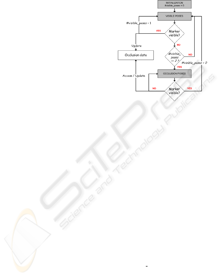
The scheme is shown in Figure 1.
We rename the poses calculate by ARToolkit-
Plus as visible poses, and the poses calculate by our
method as occlusion poses. In this way, while marker
is visible, ARToolkitPlus calculates the visible poses
and updates some data (occlusion data) that will be
used to calculate the hypothetical occlusion poses.
This data contains the follow minimum information
for each of the last two poses:
• Camera pose;
• Markers centre in pixels coordinates;
• Marker AABB (Axis Aligned Bounding Box) (Fig-
ure 2);
When the stated is changed from occlusion to vis-
ible, the number of visible poses is set to 0, so the last
Figure 1: Relation between ARToolkitPlus and Occlusion.
two visible camera poses are dynamically updated.
Notice that ARToolkitPlus is the first step of the
execution for every frame, so if one marker is par-
tially occluded and another visible marker appears in
the image, then ARToolkitPlus has more priority, and
the camera pose will be calculated with the visible
marker.
4 OCCLUSION POSES
For explaining the follow sections, we suppose that
2D coordinates correspond to the image reference
system, and the 3D coordinates correspond to the
camera reference system.
The calculation of occlusion poses is divided into
two steps: the first occlusion pose and the rest occlu-
sion poses.
4.1 First Occlusion Poses
To calculate the first occlusion pose, the translation
between the last two visible poses is applied to the last
visible pose. The rotation parameters are maintained
fixed and occlusion data is updated.
Occlusion P
0
= P
i−1
+ Tr(P
i−1
,P
i−2
); (1)
where P indicates camera pose and Tr translation.
The assumed estimation is that the camera move-
ment respect to the marker will continue in the
same way between the two first consecutive occlu-
sion frames. However,this assumption is not valid for
the next occlusion poses because the time between the
A NOVEL APPROACH TO ACHIEVE ROBUSTNESS AGAINST MARKER OCCLUSION
479
first occlusion frame and the current occlusion frame
could be enough to do any kind of movement.
4.1.1 Rest Occlusion Poses
To detect the marker in the image, ARToolkitPlus
process the image and look for objects with specific
features (square objects with black border) to finally
analyze and compare the inside of the selected ob-
ject (Schmalstieg and Wagner, 2007). Therefore, AR-
ToolkitPlus fails because detected objects do not have
marker features. However, if the marker has been par-
tially occluded, the part that is visible will be one of
the detected objects, so the new task to do is to detect
which of the candidates is the marker itself. Neverthe-
less, we only extract these candidates from ARToolk-
itPlus pipeline when occlusion is detected, to achieve
better performance. This is another reason why we di-
vide our method in two steps, since the first one (4.1)
activates the new candidate search.
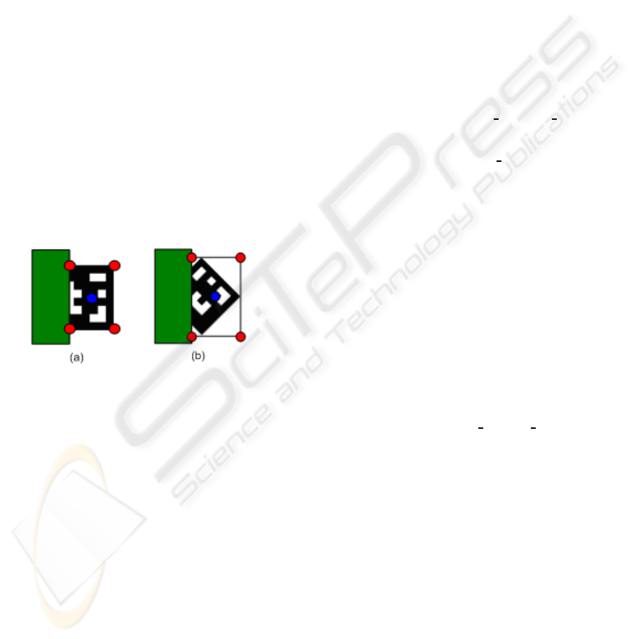
4.1.2 Candidate Selection
For each candidate we have its AABB (red points) and
centre (blue point) in image coordinates (Figure 2).
Figure 2: Occlusion when the marker is parallel to the im-
age border (a), and when the marker is rotated before the
ocllusion (b).
Moreover, we have the same data for the marker
detected in the last frame (we will refer it as reference
marker). Thus, we choose the candidate that is closest
to the reference marker and has similar area (temporal
coherence). A square centred on a reference marker
centre has been used to do not analyze all image, and
achieve better performance. With a 320x240 image
resolution we have had good results with squares that
have 50-75 pixels of radius. Furthermore, we have in-
terpreted ”similar area” as area change less than 25%.
4.2 Translation
X and Y translation in 3D coordinates is obtained us-
ing X and Y 2D translation between the centres of
the candidate and the reference marker in the im-
age. However, in occlusion context, the marker centre
translation is always the half of the marker translation
for one or both coordinates (when marker is occluded
2 pixels, the centre of the visible part of the marker
moves 1 pixel).
To know which coordinate has to be multiply, we
compare the candidate corners positions in the image
(image resolution is an ARToolkitPlus parameter). If
one of the candidate corners is in the image vertical
border, then the X translation has to be multiplied by
2. If it is in the horizontal border, then the Y transla-
tion has to be multiplied by 2.
Finally, to make the coordinates conversion, a 3D-
2D proportion is used (Section 4.6), where 3D trans-
lation is the difference between the last two visible
poses and 2D translation is the difference between the
centres of the marker in the image.
tX = propX ∗ centres distances x; (2)
where tX is the new X 3D translation, propX = TrX(
3D ) / TrX( 2D ), and centres distances is the cor-
rect marker centre translation (analogous for Y coor-
dinate).
When a Z translation is executed the size of the
objects that are in the image changes. With this as-
sumption, to detect Z translation the side sizes are an-
alyzed.
As we said in 4.1.2, we have the four corners of
the AABB, so we have always one visible side, except
in the image corners, that we will explain later. This
side will be used to do the comparisons and we will
refer it as visible side.
The process is similar to (X, Y) translation. The
difference between the sizes of the current visible side
(candidate marker) and the last visible side is multiply
by Z proportion (Section 4.6)
tZ = propZ ∗ (VSS
fi
−VSS
fi−1
); (3)
where VSS
fi
is the visible side size in frame i.
Another problem is when the marker is occluded
in the image corners, since in these positions there
are not completely visible sides. Because of this, we
can not distinct between (X, Y) translations and Z
translations in these situations. Therefore, we inter-
pret a movement in the image corner as Z translation
when the size of the partially visible sides grows or
decreases proportionally
|sideX
i
/sideX
i−1
− sideY
i
/sideY
i−1
|
˜
0 (4)
where sideH
k
is the size of the side H in frame k.
Eq 4 is the most generally interpretation, since it
only decides wrong when user moves the marker in
the image corner and the sides are occluded propor-
tionally because of (X, Y) translation.
VISAPP 2009 - International Conference on Computer Vision Theory and Applications
480
4.3 Rotation in Z Axis
The new rotation parameters are only updated for the
Z axis, since for the other axes there is not enough
information to obtain them (Section 4.5).
The rotation angle in Z axis is the same rotation
angle between two consecutive OBBs of the marker,
where OBB is the Oriented Bounding Box (red lines
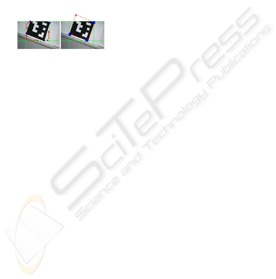
in the right column of Figure 3). To calculate the
OBB, we use the AABB, as it is shown in the left
column of Figure 3.
Figure 3: Transformation from AABB to OBB corners.
Starting in each AABB corner (intersection of the
green lines in Figure 8) and moving in X and Y direc-
tion (red arrows), for each AABB corner we choose
the point that is closest, obtaining 4 points (blue
points). Only the image area that defines the AABB is
analyzed, so a little image analysis is needed. Further-
more, we analyze the image that is already segmented
by ARToolkitPlus, so the process is faster.
However, only 3 of these 4 points belong to the
OBB, so to discard the outlier, we select the 3 points
that generate two perpendicular vectors (right column
of Figure 3). The last point of the OBB is calculated
using the parallelogram rule.
To compare the actual OBB with the OBB of the
last frame, the corners of the OBB in the last frame
are saved and updated every frame. Moreover, to do
the comparison we need the same point configuration
in both. When the first OBB is calculated in an oc-
clusion sequence, points are order in clockwise and
saved starting with the upper left corner. To obtain the
same point configuration in the next OBB, firstly, the
corners of it are ordered in clockwise. Then, we cal-
culate the all possible configurations (permutations),
and it is selected the configuration with the minimum
distance against the configuration of the last frame.
To calculate the angle between two OBBs, the an-
gle between the same side in both OBBs is used. As
they have the same point configuration, we use the
first two points that are saved, and we calculate the
vector of the side. The same process is done for the
both OBBs, obtaining two vectors, v1 and v2. Finally,
to obtain the angle, we calculate the dot product of the
two vectors.
a = acos(v1.v2/|v1||v2|) (5)
4.4 Camera Pose Update
In the previous sections, we have obtained the X, Y
and Z translation from the last frame to the actual
frame (tx’, ty’, and tz’ respectively). The rotation an-
gle in the Z axis (α) has been computed too.
Using these data, the previous pose ([ R | t ]) is
transformed in the new pose ([ R’ | t’ ]):
t
′T
= t
T
+ (tx
′
ty
′
tz
′
)
T
R
′
=
cosα −sinα 0
sinα cosα 0
0 0 1
∗ R (6)
4.5 Observations and Limitations
When a rotation in Z axis is executed, the size of the
visible side of the AABB increases, so it could be in-
terpreted as translation in Z axis too. Therefore, a
constraint has been used in order to not to mix the
both movements: When a translation in Z axis is ex-
ecuted, then the rotation angle has to be less than β,
where β is a threshold. Our experiments used a value
between 2 and 3 degrees.
In our approach, the different sizes of the visi-
ble side have been used to calculate the Z translation
(Section 4.2). However, they could be used to calcu-
late the rotation in X (difference between horizontal
visible sides) and Y (diference between vertical vis-
ible sides) axes provided that the Z translations are
forbidden. Nonetheless, Z translation is more impor-
tant and usual movement than pitch and yaw.
Although our method provides an aproximation of
the pose (4DOF), we think that it is enough to some
tasks. Furthermore, our technique does not need espe-
cial markers or extra prepared environments, so it can
be used in scenes that are already prepared for AR-
ToolkitPlus without installing anything. Our choices
have been conditioned to achieve a global method that
could be integrated in any environment and marker
tracking software with squared markers. We take pri-
ority to easy adaptability.
4.6 Proportion Values
The propX, propY and propZ proportions are calcu-
lated using the similar triangles rule in a pinhole cam-
era model and supposing X,Y or Z pure translations.
Assuming fx is the focal length in X axis, X3D
1
the 3D coordinate in X axis, X3D
2
the 3D coordinate
in X axis of the same point in the next frame, X2D
1
and X2D
2
their respective projections in the image,
and Z value is maintaned fixed (top of Figure 4); the
A NOVEL APPROACH TO ACHIEVE ROBUSTNESS AGAINST MARKER OCCLUSION
481
resulting propX = TrX(3D) / TrX(2D) is
propX =
(X3D
2
− X3D
1
)
fx
Z1
∗ (X3D
2
− X3D
1
)
=
Z1
fx
(7)
The process to calculate propY is anologous, replac-
ing X axis by Y axis.
In the other hand, to calculate propZ, the Z value
changes and the X value (or Y for Y axis) is main-
tained fixed (X3D
1
=X3D
2
) (bottom of Figure 4). Fur-
thermore, propZ is divided in propZX and propZY,
since we are working with images that have not got
square resolution, so fx and fy are different. Taking
everything in consideration, propZX and propZY ex-
presions are
propZX =
TrZX(3D)
TrZX(2D)
=
(
X2D
1
X2D
2
− 1) ∗ Z1
(X2D
2
− X2D
1
)
(8)
propZY =
TrZY(3D)
TrZY(2D)
=
(
X2Y
1
X2Y
2
− 1) ∗ Z1
(Y2D
2
−Y2D
1
)
(9)
Note that we have to detect when the visible side is
vertical to apply propZY, and when it is horizontal to
apply propZX, in Equation 3.
Figure 4: Pure X translation (top) and pure Z translation
(bottom) in a pinhole camera model.
5 EXPERIMENTS
5.1 Computational Cost
ARToolkitPlus has been tested with our occlusion
management in a PC (P4 3GHz, 2GB RAM) and PDA
(Dell Axim X 50v). Thus, it only adds computational
cost in the PDA execution (
˜
2 frames per second),
when ARToolkitPlus is able to calculate the new pose.
In these situations, additionally to calculate the new
pose, the occlusion data is saved, decreasing the fps
value. When the marker is occluded, ARToolkitPlus
does not execute the calculus to obtain the camera
pose with 4 coplanar points, so this time is used to
calculate occlusions, and the final fps value is com-
pensated.
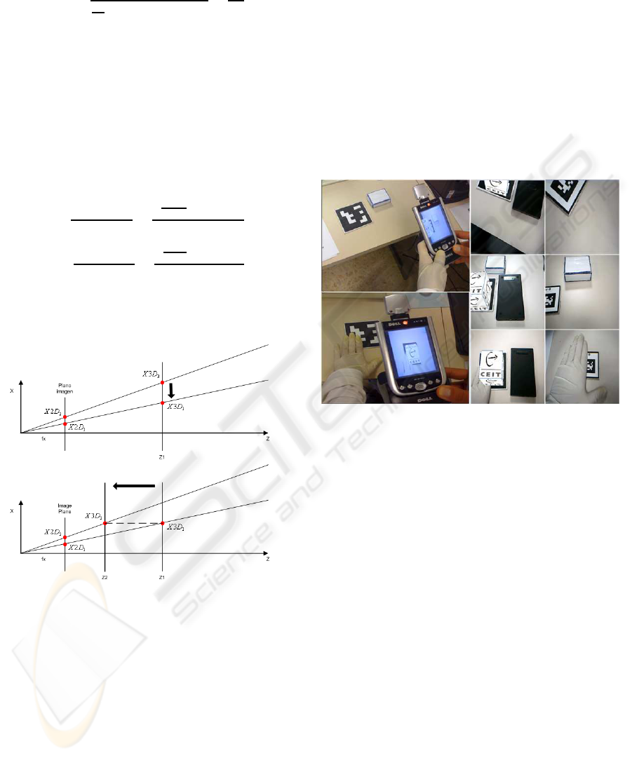
5.2 Results
In this section, we present some images of the occlu-
sion execution to show how it works (Figure 5). Fur-
thermore, the third column shows how ARTag fails in
similar cases in which our method still works, provid-
ing that our approach is more robust.
Figure 5: ARToolkitPlus output with our occlusion manage-
ment, using a PDA (left) and PC (middle). ARTag output
for similar cases (right).
5.3 Edge Segmentation
As we explained in Section 4.1.1, ARToolkitPlus
looks for black square shapes to detect the marker,
and Candidate selection compares the candidates area
with the markers reference area. That is why, when
user occludes the marker with black objects ARToolk-
itPlus detects all as one object (right column of Fig-
ure 6). Thus, the areas difference is too big, and
our method fails. To overcome this problem, we
have implemented initial prototype (only for PC) that
uses edge segmentation when the binary thresholding
fails (middle column of Figure 6). This is similar to
ARTag, but without using heuristics to close contours,
since they add extra time consuming.
6 CONCLUSIONS-FUTURE
WORK
In this paper a novel approach has been presented to
estimate the X, Y, Z translation and rotation in Z axis
VISAPP 2009 - International Conference on Computer Vision Theory and Applications
482

Figure 6: Detected marker candidate (red contour), using
binary segmentation (left), and using edge segmentation
(middle). The green rectangle is the AABB used to cal-
culate new camera pose with edge segmentation. ARToolk-
itplus output using edge segmentation (right).
of the marker when it is occluded. It needs a little
image analysis, and computational cost is very low,
so it is ideal for mobile devices. In addition, only
one marker (without modification) is necessary, and
it has not got ARToolkitPlus dependence. (Simon,
2000; Yuan, 2006) are markerless solutions that detect
planar surfaces to calculate the camera pose, so this
method could be implemented in these approaches
too. Although we work with markers, we dont use
the information that is coded inside them, so we re-
ally work with planar surfaces.
In our future work we are going to implement the
same solution presented in Section 5.3, but for mobile
platforms. We also are going to design a new marker.
Adding some extra features to the marker we will able
to use the same procedure as (Wagner et al., 2008)
and (Malik et al., 2002), but despite of extract features
from the environment or doing incremental tracking,
we will extract all information from the marker every
frame, making a tracking by detection, and avoiding
most of problems that these solutions have.
ACKNOWLEDGEMENTS
This work was partially funded by a grant of the
Basque Country Government and the national project
RASMAP.
REFERENCES
de Ipia, D. L., Mendonca, P. R. S., and Hopper, A. (2002).
Trip: A low-cost vision-based location system for
ubiquitous computing. 6(3):206–219.
Fiala, M. (2005). Artag, a fiducial marker system using dig-
ital techniques. Proceedings of the 2005 IEEE Com-
puter Society Conference on Computer Vision Pattern
Recognition (CVPR’05), pages 590–596.
Kato, H. and Billinghurst, M. (1999). Marker tracking and
hmd calibration for a video-based augmented reality
conferencing system. In IWAR ’99: Proceedings of
the 2nd IEEE and ACM International Workshop on
Augmented Reality, page 85, Washington, DC, USA.
IEEE Computer Society.
Kato, H., Billinghurst, M., and Poupyrev, I. (2000). AR-
ToolKit version 2.33: A software library for Aug-
mented Reality Applications.
Lee, G. A., Billinghurst, M., and Kim, G. J. (2004). Oc-
clusion based interaction methods for tangible aug-
mented reality environments. In VRCAI ’04: Pro-
ceedings of the 2004 ACM SIGGRAPH international
conference on Virtual Reality continuum and its ap-
plications in industry, pages 419–426, New York, NY,
USA. ACM.
Malik, S., Roth, G., and Mcdonald, C. (2002). Robust
2d tracking for real-time augmented reality. In Proc.
Conf. Vision Interface, pages 399–406.
Mohring, M. (2004). Video see-through ar on consumer
cell-phones. In Mixed and Augmented Reality, 2004.
ISMAR 2004. Third IEEE and ACM International
Symposium on, pages 252–253.
Schmalstieg, D. and Wagner, D. (2007). Experiences with
handheld augmented reality. In The Sixth IEEE and
ACM International Symposium on Mixed and Aug-
mented Reality (ISMAR ), pages 3–15.
Simon, G. (2000). Markerless tracking using planar struc-
tures in the scene. In Augmented Reality, 2000.
(ISAR 2000). Proceedings. IEEE and ACM Interna-
tional Symposium on, pages 120–128.
Tateno, K. (2007). A nested marker for augmented reality.
In Virtual Reality Conference, 2007. VR ’07. IEEE,
pages 259–262.
Wagner, D., Langlotz, T., and Schmalstieg, D. (2008).
Robust and unobtrusive marker tracking on mobile
phones. International Symposium on Mixed and Aug-
mented Reality, IEEE,.
Wagner, D. and Schmalstieg, D. (2007). Artoolkitplus for
pose tracking on mobile devices. In Proceedings of
12th Computer Vision Winter Workshop (CVWW’07).
Yuan, C. (2006). Markerless pose tracking for augmented
reality. Advances in Visual Computing. Second Inter-
national Symposium, pages 721–730.
Zhang, X., Fronz, S., and Navab, N. (2002). Visual marker
detection and decoding in ar systems: A comparative
study. In ISMAR ’02: Proceedings of the 1st Interna-
tional Symposium on Mixed and Augmented Reality,
page 97, Washington, DC, USA. IEEE Computer So-
ciety.
A NOVEL APPROACH TO ACHIEVE ROBUSTNESS AGAINST MARKER OCCLUSION
483
