
A MULTI-LAYERED MICROFLUIDIC DEVICE
FOR MAGNETOPHORETIC CELL SEPARATION
Hye-Lyn Lee, Suk-Heung Song, Hee-Taek Lim, Hyung-Joon Kim, Min-Suk Park and Hyo-Il Jung
School of Mechanical Engineering, Yonsei University, Seoul, Republic of Korea
Keywords: Multi-layered microfluidic channel, Magnetophoretic cell separation, Microelectromagnet, Microbeads,
Magnetic field.
Abstract: In this paper, we present the design and experimental results of a multi-layered microfluidic electromagnetic
cell separation device. Our channel consists of top and bottom layers in order to separate magnetically
labeled cells in the vertical direction. Rapid separation of magnetic beads in top and bottom channel can be
used in high throughput screening to monitor the efficacy and drug compounds. The experiments using the
device were carried out with 4.5μm magnetic bead and magnetic labeled Jurkat cell under electromagnetic
field of 1.55mT. Without the magnetic field, the magnetic labeled cells started to flow from the bottom inlet
and exit out of the bottom channel outlet. In the presence of the magnetic field, the cells started in bottom
channel are attracted upward by the electromagnetic field and flow through the top layered. Finally, the
labeled cells flow out the top channel outlet. The separation efficiencies of the multi-layer structured
microfluidic channel showed more than 95%. We found that the multi-layer structured microfluidic channel
was very effective in enhancing the separation. This microfluidic channel can be potentially applied to Lab-
on-a-chip system because of its attractive features such as high throughput, continuous sorting, simple and
rapid fabrication.
1 INTRODUCTION
There is a growing interest of microfluidic cell
separation systems as they are useful for high
throughput drug screening and medical diagnosis
(Inglis at al. 2004) (Pamme and Wilhelm, 2006).
The Fluorescent Activated Cell Sorter (FACS) is one
of the most common methods to detect and separate
cells but the bench-top volume of the device is a
barrier to its miniaturization. A microfluidic device
is a proven way of minimization and there have been
several reports regarding the separation of specific
cells in an optical microfluidic system (Wolbers et al.
2004). However, optical systems have the
disadvantage of requiring external observation and
are not suitable for opaque samples like blood.
A Magnetic Activated Cell Sorter (MACS) can
overcome all the defects of cell sorters. It is simple
to operate and is generally not affected by the
electrical properties of a solution, pH, temperature or
impurities (Pamme 2006). Separation of human
peripheral T lymphocytes has been reported using
MACS with permanent magnets and quadropole
fields (Sun et al. 1998). Microfluidic MACS for
HeLa cell and macrophage sorting have recently
been developed (Pamme and Wilhelm 2006).
It is a generally, thought that conventional
magnetophoretic separating devices produce small
magnetic fields in the microfluidic channel. Also,
most use mono-layered channel that separate in the
horizontal direction (Kim at al. 2007).
In this research, we demonstrate a new
microfluidic channel consisted of top and bottom
layers in order to separate in the vertical direction.
This device can get easily high degree of separation
efficiency although in the small magnetic fields.
2 MATERIALS AND METHOD
2.1 Theory
There are three forces acting on a magnetically
labeled cell surface: magnetic force, drag and
gravity as shown in Fig.1.
Because the effect of gravity is negligible owing
286
Lee H., Song S., Lim H., Kim H., Park M. and Jung H. (2009).
A MULTI-LAYERED MICROFLUIDIC DEVICE FOR MAGNETOPHORETIC CELL SEPARATION.
In Proceedings of the International Conference on Biomedical Electronics and Devices, pages 286-289
DOI: 10.5220/0001776702860289
Copyright
c
SciTePress
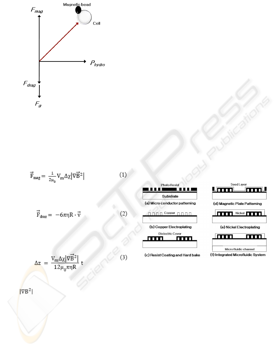
Figure 1: Three forces acting on the surface of a cell.
to the small size of the magnetic bead labeled cell
(Qasem et al. 2004), the forces responsible for
deflection of cells coated with magnetic beads are
magnetic and drag forces. The magnetic force
exerted on a magnetic bead in magnetic field can be
calculated as follows (Williams et al. 1999):
Hydrodynamic drag force is estimated according to
the Stokes drag equation:
Finally, considering the force balance between
magnetic and hydrodynamic drag (neglecting the
inertial term of Newton’s law), the deflection of the
cell is given by (Qasem et al. 2004):
In Eq. (3), V
m
is a volume of magnetic beads. Δχ
was calculated from the literature (Lagae et al. 2005).
Finally,
as determined by measuring magnetic
fields with a gauss meter (LakeShore 475 DSP) and
calculating based on the inverse square law. The
deflection of the cell, Δz, generated by one magnetic
bead attached on the cell surface was 4.5 μm. In
most cases, the number of magnetic beads bound
with cell was more than 1, so the vertical deflection
should be more than 17.5 μm. We fabricated a
microfluidic device to separate cells assuming that
Δz is more than 17.5 μm.
2.2 Fabrication
2.2.1 Electromagnet
The microelectromagnet was fabricated using
MEMS technology. The fabrication process for on-
chip microelectromagnet is in Fig. 2: (a) SiO2 was
deposited 1μm on a double-side-polished Si wafer
by furnace and the microconductor was patterned
using UV-lithography; (b) a copper microcoil, as a
conductor for the microelectromagnet, was
manufactured by 25μm thick electroplating with a
photoresistor mold. For the electrical insulation, the
dielectric layer based on polymer material (AZ 4620,
Clariant, Korea) was deposited between the
microcoil and the magnetic plate; (c) The polymer,
as a dielectric layer, was encapsulated on the
microcoil and was hard-baked; (d) The seed layer,
Ti/Ni 500/3000Å, was deposited onto the dielectric
layer for electroplating of the nickel plate; (e) the
nickel, as a magnetic plate, was electroplated 25μm
thick and (f) the PDMS microfluidic channel system
was integrated.
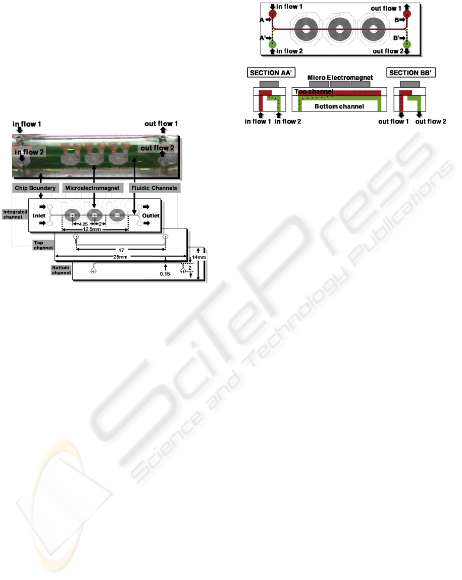
The size of the electromagnet is 4 x 4 mm
2
and
the height of the magnetic plate is 25 μm.
Figure 2: Fabrication processes of the microelectromagnet
and microfluidic system.
2.2.2 Microfluidic Channel
A microfluidic channel was fabricated according to
standard softlithography and replica molding process.
The silicon wafer was washed first by methanol,
followed by acetone, and de-ionized water, then a
SU-8 negative epoxy-based photoresist (SU-8 2100,
MicroChem Corp.) was spin-coated on the wafer.
The spin-coated wafer was baked using a hot plate
(95°C, 35 min) to remove unwanted area from the
photoresist. The wafer was then exposed to UV light
(λ = 365 nm, 60 s), baked again in two steps (65°C,
1 min and 95°C, 15 min), and developed by the SU-
8 developer (Sigma Aldrich) for 15 min. The result
was a 130 μm high photoresist mold. After
A MULTI-LAYERED MICROFLUIDIC DEVICE FOR MAGNETOPHORETIC CELL SEPARATION
287
preparing the SU-8 mould, a PDMS gel mixture (DC
184-A:B = 9:1, Dow Corning) was poured on the
wafer, the gel mixture was baked in an oven (80°C,
45 min) and detached from the mold. The PDMS
microfuidic channel was finally treated with O
2
plasma and bonded with a glass substrate. The size
of this device is 25mm x 14mm x 5mm and the
microfluidic channel length is 17mm, the width is
150μm and the depth is 100μm.
Figure 3: Illustration of the multi-layered microfluidic
channel with on-chip electromagnet.
2.3 Cell Culture
Jurkat clone E6-1 cells (Organ: acute T cell
leukemia/ human blood) were cultured under
standard conditions (37°C, 5%CO
2) in RPMI-1640
medium comprised of 10% (v/v) fetal bovine serum
(FBS) and 1% antimycotic antibiotic (all purchased
from Cambrex, USA).
2.4 Sample Preparation
Dynabeads
®
CD3 are superparamagnetic, micro
sized particles with a characteristic polymer surface
for coupling with CD3 T-Cells, thus making it
possible to sort out the human T cells in this
experiment. Dynabeads
®
CD3 (4x10
8
bead/ml, 25 μl)
and Jurkat clone E6-1 cells (1x10
7
cell/ml, 1ml)
were incubated for 10 min at 2-8°C with gentle
tilting and rotation. Finally, Jurkat cells (13 µm
diameter) are bound with magnetic beads CD3 (4.5
µm diameter).
2.5 Experimental Set-up
A schematic view of the multi-layered microfluidic
channel using on-chip electromagnet is illustrated in
figure 4. The multi-layered microfluidic channel is a
Figure 4: Schematic diagram of the multi-layered
microfluidic channel.
straight type with a square cross-section. The fluid is
assumed incompressible the flow will be laminar
and boundary condition is the no-slip on the channel
walls. The magnetic beads and cell mixture started
in bottom channel at flow rate of 5μL/min are
attracted upward by the electromagnetic field and
flow through the top layered. Finally, magnetic
beads flow out the top channel outlet.
A syringe pump (KDS scientific, CMA
instruments) is connected to the microfluidic
channel to supply different types of fluid through
two syringes (sample solution syringe and buffer
solution syringe). The syringes and channel inlets
were linked by Teflon tubes (500 μm, Nano Port).
The microfluidic channel was placed on an optical
microscope and monitored by a CCD camera. We
used a microelectromagnet of 1.55mT (Tesla) placed
on the top of the main channel.
3 RESULTS AND DISCUSSION
The sample solution was flowed through a
microfluidic channel and the Jurkat cells labeled
magnetic beads were separated by a 1.55mT
microelectromagnet at 5μL/min of flow rate.
Magnetic beads are introduced to magnetic fields
and then experience a magnetic field while flowing
in the microfluidic channel.
Figure 6 shows comparison of the efficiencies
without and with magnetic field by electromagnet.
In the absence of magnetic fields, the flow of cells
labeled magnetic beads is shown negligible in
outflow 1 of top channel with an efficiency of 2.8%.
However, in the presence of magnetic fields, the
magnetically labeled cells are dominant in outflow 1
with a high efficiency of 95.3%. It demonstrates
magnetic beads were deflected and separated
through outlet 1 when a magnetic field was
introduced.
BIODEVICES 2009 - International Conference on Biomedical Electronics and Devices
288
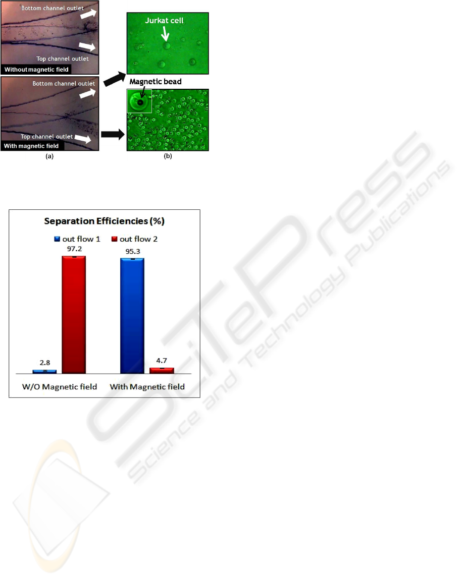
Figure 5: (a) Photographic image of microfluidic channel
(b) Photographic image of Jurkat cells and magnetic beads
from outlet of the channel.
Figure 6: Experimental results of the separation
efficiencies.
4 CONCLUSIONS
A new multi-layered channel for separating cells has
been introduced using microelectromagnet. Our
experiments demonstrate that specific cells can be
separated simply using a multi-layered microfluidic
channel with high efficiencies.
The efficiency of the separation by our approach
was comparable with that of conventional
magnetophoretic cell sorters (Bu at al. 2008)
(Smistrup at al. 2005). Our results identify a new
multi-layered microfluidic channel to isolate cells
for drug discovery and Lab-on-a-chip system
because of its attractive features such as high
throughput, continuous sorting, simply and rapidly
fabricated system.
ACKNOWLEDGEMENTS
This work was supported by National Core Research
Center (NCRC) for Nanomedical Technology of the
Korea Science & Engineering Foundation (Grant no.
R15-2004-024-01001-0), Seoul Research &
Business Development (R&BD Program, 11128)
and Korea Research Foundation Grant funded by the
Korean Government (MOEHRD) (KRF-2007-313-
D00073).
REFERENCES
Inglis, D., Riehn, R., Austin, R., & Sturm, J. 2004.
Continuous microfluidic immunomagnetic cell
separation. Applied Physics Letters, 85, 5093.
Pamme, N., & Wilhelm, C. 2006. Continuous sorting of
magnetic cells via on-chip free-flow magnetophoresis.
[Article]. Lab on a Chip, 6(8), 974-980.
Wolbers F, Andersson H, van den Berg A, Vermes I. 2004.
Apoptosis induced kinetic changes in autofluorescence
of HL60 cells-possible application for single cell
analysis on chip. Apoptosis 9:749–755
Pamme N. 2006. Magnetism and microfluidics. Lab Chip
6:24–38
Sun L, Zborowski M, Moore LR, Chalmers JJ. 1998.
Continuous, flow-through immunomagnetic cell
sorting in a quadrupole field. Cytometry 33:469–475
Kim, H., Son, O., Kim, K., Kim, S., Maeng, S., & Jung, H.
2007. Separation of apoptotic cells using a
microfluidic device. Biotechnology Letters, 29(11),
1659-1663.
Qasem R, Victor S, Daniel P, Chen Y. 2004. On-chip
microelectromagnets for magnetic-based bio-
molecules separation. J Magnetism and Magnetic Mat
281:150–172
Williams PS, Zborowski M, Chalmers JJ. 1999. Flowrate
optimization for the quadrupole magnetic cell sorter. Anal
Chem 71:3799–3807
Lagae L, Wirix-Speetjens R, Liu CX, Laureyn W, Borghs
G, Harvey S, Galvin P, Ferreira HA, Graham DL,
Freitas PP, Clarke LA, Amaral MD. 2005. Magnetic
biosensors for genetic screening of cystic fibrosis.
IEEE Proc Circuit Device Syst 152:393–400
Bu, M., Christensen, T. B., Smistrup, K., Wolff, A., &
Hansen, M. F. 2008. Characterization of a
microfluidic magnetic bead separator for high-
throughput applications. Sensors and Actuators, A:
Physical, 145-146(1-2), 430-436.
Smistrup, K., Hansen, O., Bruus, H., & Hansen, M. 2005.
Magnetic separation in microfluidic systems using
microfabricated electromagnets-experiments and
simulations. Journal of Magnetism and Magnetic
Materials, 293(1), 597-604.
A MULTI-LAYERED MICROFLUIDIC DEVICE FOR MAGNETOPHORETIC CELL SEPARATION
289
