
HYBRID TERRAIN VISUALIZATION BASED ON LOCAL
TESSELLATIONS
E. G. Paredes
1
, C. Lema
2
, M. Amor
2
and M. B´oo
3
1
Dept. Electronic and Computer Eng., Univ. Santiago de Compostela, Santiago de Compostela, Spain
2
Dept. Electronics and Systems, Univ. Coru˜na, A Coru˜na, Spain
3
Dept. Electronic and Computer Eng., Univ. Santiago de Compostela, Santiago de Compostela, Spain
Keywords:
Hybrid terrain representation, Interactive visualization, Tessellation, Convexification.
Abstract:
Hybrid terrain models represent an effective approach to combine geographic data with different acquisition
properties. Terrain models constituted by regular grid elevation data may locally integrate detailed TIN meshes
to represent morphologically complex terrain features and artificial objects. However, direct rendering of
hybrid terrain models poses additional difficulties: holes and geometric discontinuities between the borders of
the different parts would appear in the images. In this paper we present two new software based proposals for
efficient hybrid terrain visualization. Both proposals generate high-quality geometrically continuous models
and support multiresolution methods over regular grids.
1 INTRODUCTION
Interactive visualization of large Digital Terrain Mod-
els (DTM) is an important challenge in the field of
computer graphics. Due to the increasing utilization
of applications that use 3D geographic models on a
large scale –such as Geographic Information Systems
(GIS), cartography, urban planning, virtual reality and
computer games– in recent years, differentmethods to
optimize the process of visualization have been suc-
cessfully developed (VTerrain, 2008). Most of the op-
timization techniques are based on employing several
representations of the original model with different
Level Of Detail (LOD) (Luebke et al., 2002).
An interesting situation arises when one base rep-
resentation of the terrain exists together with another,
in a different type of representation, for areas requir-
ing a finer sampling, such as topographicallycomplex
terrain features and artificial man-made microstruc-
tures. This permits the enhancement of existing reg-
ular terrains by adding details to specific regions of
interest without having to increase the overall resolu-
tion or having to convert the whole terrain model into
a finer and irregular representation. Microstructures
integrated in grid-based terrain models also improve
the graphical and perceptual quality of visualized ter-
rain models, since they provide a more precise and
adequate geometry, shading, and illumination of mor-
phologically important terrain features (typically af-
fecting less than 20% of the complete terrain surface).
Proposals analyzing the problem of directly rep-
resenting hybrid terrain models have recently ap-
peared. An adaptive tessellation procedure to con-
nect both meshes is suggested in (Dykes et al., 2005)
to avoid discontinuities in the junction between rep-
resentations. However, no specific tessellation algo-
rithms were proposed in these works. Based on this
idea, a technique for interactive visualization of hy-
brid meshes was presented in (B´oo et al., 2007; Amor
and B´oo, 2008). The main characteristic of this Hy-
brid Meshing (HM) algorithm is that an efficient LOD
level independent scheme is used for representing the
local adaptive triangulation between mesh borders.
In this paper we present two software oriented al-
gorithms for the visualization of hybrid terrains. Our
proposals, inspired in the hardware oriented algorithm
developed in (B´oo et al., 2007; Amor and B´oo, 2008),
are based on the generation of the additional required
triangles following a cell-based strategy. Specifically,
we have employed two algorithms to generate those
triangles. The first one computes local tessellations
using the incremental randomized triangulation algo-
rithm for triangulating polygons (Seidel, 1991). The
second one adapts the HM algorithm to a software im-
64
Paredes E., Lema C., Amor M. and Bóo M. (2009).
HYBRID TERRAIN VISUALIZATION BASED ON LOCAL TESSELLATIONS.
In Proceedings of the Four th International Conference on Computer Graphics Theory and Applications, pages 64-69
DOI: 10.5220/0001768200640069
Copyright
c
SciTePress
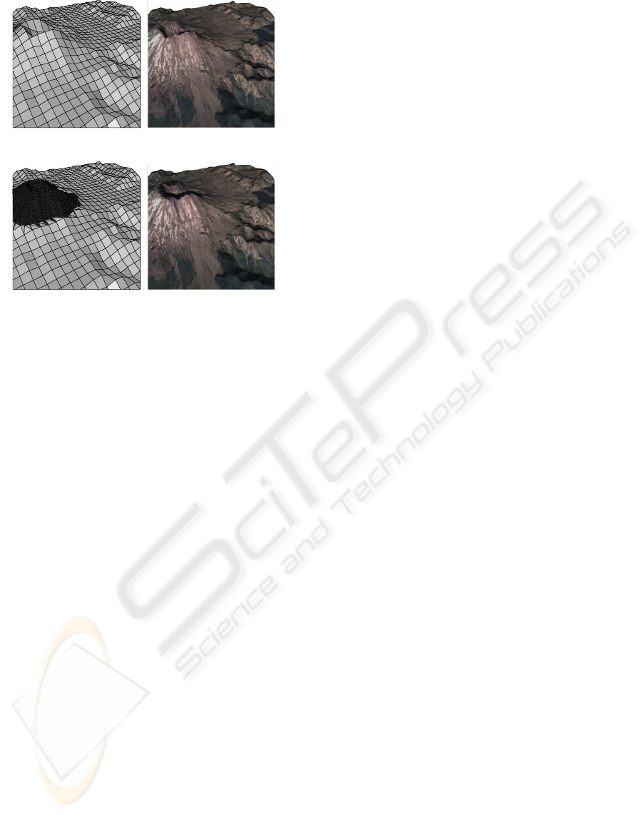
(a) (b)
(c) (d)
Figure 1: Hybrid terrain model. (a) Grid (b) Grid with tex-
ture (c) Hybrid model (d) Hybrid model with texture.
plementation. A performanceevaluation of our exper-
imental implementation of both methods and a com-
parison between them is presented here.
2 HYBRID REPRESENTATION
OF TERRAIN MESHES
Digital Terrain Models are represented in different
ways depending on several factors such as the nature
of the capturing technology, input data, or applica-
tion domain. Digital Elevation Model (DEM) (Lue-
bke et al., 2002) is a simple and widely employed
representation method that stores a collection of regu-
larly spaced elevation samples of the terrain surface in
a gridded 3D mesh. An alternative data model for ter-
rain representation is the Triangulated Irregular Net-
works (TIN) (Luebke et al., 2002). TIN meshes ap-
proximate the terrain by a set of non-overlappingcon-
tiguous triangles, generated by connecting a finite set
of irregularly spaced sampled data points.
Hybrid representation of terrain meshes integrates
information from different data models, usually from
DEM and TIN. These hybrid models act as a memory-
efficient approach for detailing terrains with complex
topographic structures. But, as data points are usually
provided from different measuring systems, a method
to connect the data is required to avoid discontinuities
in the junction of the meshes.
When real-time visualization is needed, multires-
olution techniques are often used. However, includ-
ing multiresolution in hybrid terrains implies that the
connections between DEM and TIN models would
depend on the LOD. Due to this dependence, pre-
computingand transmitting LOD-dependent informa-
tion would not be optimal. The solution presented
in (Yang et al., 2005) is based on the generation of
a preprocessed mesh combining both representations.
Specifically, the Delanuay triangulation of square tiles
of the grid is performed according to the TIN infor-
mation. The main disadvantage of this method is the
implied modification of the original data.
We present in this paper a software oriented solu-
tion based on the local tessellation of the grid cells.
Our proposal consists in generating additional trian-
gles to join the models, following the strategy devel-
oped on (B´oo et al., 2007; Amor and B´oo, 2008). This
strategy leads to the generation of high quality mod-
els, as it avoids any modification of the original data.
Figure 1 shows an example of application. The first
two subfigures present a grid and the enriched ver-
sion with a texture. The last subfigures are based on
the hybrid model representation. Note that the higher
quality of the image is associated with the utilization
of a detailed TIN model of the crater.
The final hybrid model is formed by the union of
the grid and TIN in a single, coherent mesh. The gen-
eration is performed as follows: first, the entire TIN
and non covered cells of the grid (NC cells) are di-
rectly rendered; next, completely covered grid cells
(CC cells) are eliminated, as they will be replaced by
the more detailed TIN data; finally, those grid cells
partially covered (PC cells) by the TIN have to be
adaptive tessellated. This local tessellation strategy
was selected due to its simplicity and the relatively
easy adaptation for use in conjunction with LOD sys-
tems. An interesting consequence of joining models
through a local, cell-based strategy is that high quality
triangulations are generated.
In this paper we work with two tessellation algo-
rithms, based on the incremental randomized triangu-
lation algorithm (Seidel, 1991) and a software imple-
mentation of the HM strategy suggested in (B´oo et al.,
2007; Amor and B´oo, 2008).
3 PROPOSAL BASED ON THE
INCREMENTAL RANDOMIZED
TRIANGULATION METHOD
Our first proposal is based on the identification of the
non covered part of each PC cell and the utilization
of a standard polygon triangulation algorithm to con-
nect the TIN and grid models. The first step is the
HYBRID TERRAIN VISUALIZATION BASED ON LOCAL TESSELLATIONS
65
TIN
v1
v2
v3
v4
v5
c3
c0
c1
c2
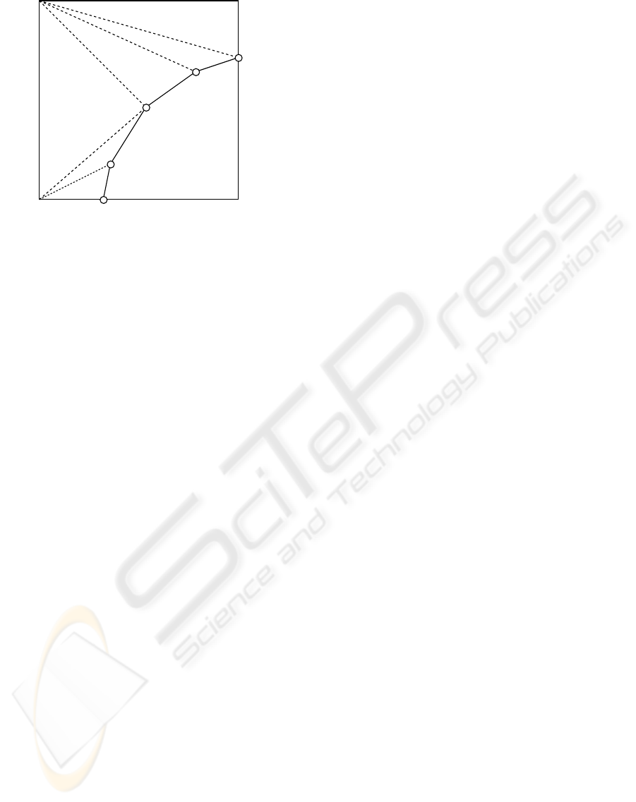
Figure 2: Corner tessellation example.
identification of the polygon made by the non-covered
grid cell corners and the vertices of the TIN bound-
ary falling into this cell. As shown in the example
of Figure 2, the identification is performed on the XY
projection of the meshes. In this example the polygon
to be tessellated is made by the cell corners c
0
, c
1
, c
3
and the TIN boundary vertices v
1
− v
5
. Note that to
assure a cell-based tessellation the intersection ver-
tices between TIN boundary and cell edges have to
be included. In the example represented in Figure 2,
vertices v
1
and v
5
were included for that purpose.
In the second step of the algorithm, the objective
is to perform a fast triangulation locally for each PC
cell. As the vertices of the grid in the cell may be
different in each LOD, the tessellation is performed
after extracting the level of detail selected by the mul-
tiresolution model. Consequently, the triangulations
are LOD dependent and have to be completely recal-
culated every frame.
We have selected for our implementation, among
all polygon tessellation methods, the Incremental
Randomized Triangulation algorithm (Seidel, 1991).
This algorithm has been widely implemented due to
its simplicity and efficiency. Good results in terms of
quality are obtained following this cell-based strategy
as will be shown in Section 5.
4 PROPOSAL BASED ON THE
HYBRID MESHING METHOD
The HM algorithm was presented in (B´oo et al., 2007;
Amor and B´oo, 2008) as a hardware oriented method
to achievehigh performanceand good quality in inter-
active visualization of hybrid terrains. The algorithm
generates an efficient LOD level independent repre-
sentation which is used for the adaptive triangulation
of every PC cell of the model.
The HM algorithm has two main cores: the local
convexification of the TIN and the adaptive tessella-
tion of the resulting convex structure. The convexifi-
cation of the TIN can be performed as a preprocessing
step and the corresponding information efficiently en-
coded. As this information can be precomputed and
encoded, the triangles associated with this step can be
generated in run-time by simple decoding operations.
On the other hand, the final tessellation to be executed
in run-time is very simple, due to the convex structure
of the TIN. This will achieve good results in terms of
execution time for this algorithm.
4.1 Triangulation between Tin and Grid
using Convex Tin Structures
During the rendering process, the grid cells partially
covered by a TIN mesh are connected with TIN
boundary vertices. Assuming that the TIN boundary
has been previously convexified, the method works
generating triangles that connect uncovered cell cor-
ners of the grid with consecutive TIN vertices while
the introduced triangle does not overlap with the TIN.
The shift in the grid corner employed is easily de-
tected by evaluating the angles between the corner
and consecutive vertices of the TIN, which is effi-
ciently implemented by testing the sign of the cross
product of consecutive edges in the TIN boundary.
Consider the example shown in Figure 2 where
a partially covered (PC) cell and the corresponding
convex TIN silhouette are depicted. TIN boundary
vertices (v
1
, v
2
, v
3
, v
4
, v
5
) and the cell corners uncov-
ered by the TIN (c
3
, c
0
, c
1
) are assumed to be pro-
cessed in a clockwise order. The HM algorithm acts
by connecting the list of corners with the list of ver-
tices following a sequential order. This way, c
3
cor-
ner is consecutively connected with the vertices of the
boundary where possible. In this example corner c
3
is
connected with vertices v
1
, v
2
and v
3
, but not with
v
4
because the new triangle (c
3
, v
3
, v
4
) would overlap
with the TIN. Therefore, corner c
0
is then selected and
connected with v
4
and with v
5
.
4.2 Incremental Convexification
As the triangulation process requires a properly con-
vexified TIN boundary to work without flaws, a con-
vexification process for the TIN boundary is locally
performed in each cell. The resulting convexified
boundary is efficiently stored, for all different con-
vexification levels, in a simple and lightweight data
structure.
The convexification inside each cell has three
steps: compute the convex hull of the TIN boundary
GRAPP 2009 - International Conference on Computer Graphics Theory and Applications
66
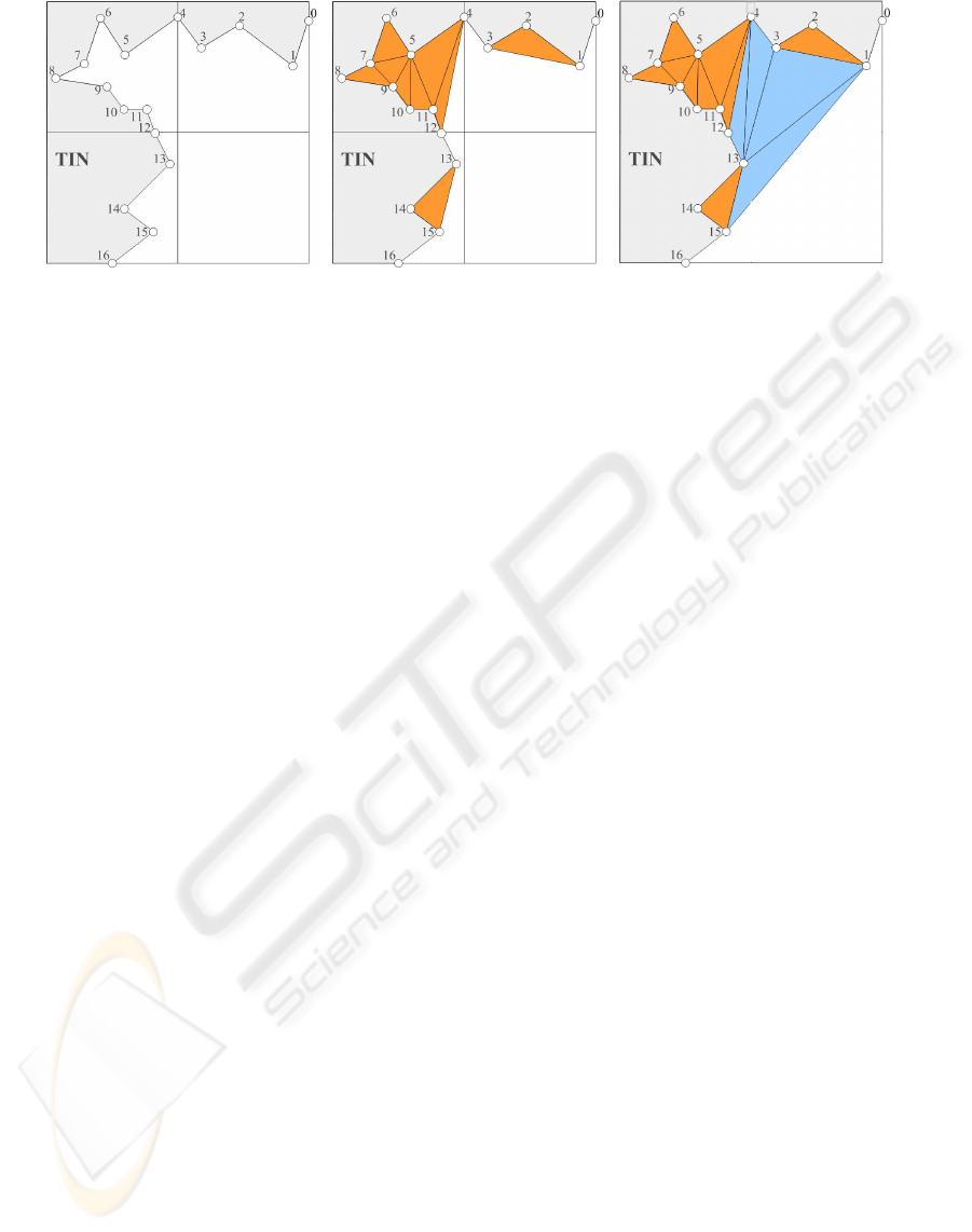
(a) (b) (c)
Figure 3: Four cells of a grid with the TIN silhouette. (a) Before convexification (b) Finest LOD level convexification (c)
Coarser level convexification.
in the cell, identify concave cavities on the boundary
and, finally, triangulate those cavities. Following this
cell-based strategy and to assure a local tessellation, it
is assumed that there is a vertex in every intersection
point between the TIN boundary and the cell borders.
In the first step the convexification is performed
for the finest grid resolution level. Figure 3(a) shows
four cells corresponding to the finest resolution level
of the grid and the corresponding TIN silhouette cov-
ering this area. The TIN is depicted in grey, the TIN
boundary is explicitly marked and vertices on it are
indicated with circles. The local convexification re-
sults are indicated in Figure 3(b). Local convex hulls
are delimited by vertices {0, 1, 3, 4} (up-right cell),
{4, 12} (up-left cell) and {12, 13, 15, 16} (down-left
cell). Once the convex hull for each cell is deter-
mined, the triangles inside the caves are generated us-
ing any standard tessellation algorithm.
After computing the convex hull for all cells in
the finest level of detail, the following coarser level is
processed following an incremental strategy and the
triangles generated in previous convexifications are
preserved. Following the previous example of Fig-
ure 3(a), the next coarser level of detail is analyzed
in Figure 3(c). In this figure, the new convexification
triangles are shown and, with a different colour, the
ones generated in previous steps. The new local con-
vex hull is determined by vertices {0, 1, 15, 16}. The
procedure continues for each cell and each level of the
grid until the coarsest level is processed.
4.3 Hybrid Model Representation
As has been shown previously, the key point of the
HM algorithm for achievinggood performanceresults
is the compact and efficient representation of the con-
vexified boundary information of the TIN. The sim-
plicity of the tessellation procedure is directly related
to this representation as well. As a result, and given
a LOD, the corresponding triangles can be extracted
from this representation in run-time by means of very
simple decoding operations.
Together with this information, two additional
lists are used to directly identify the cells and the ver-
tices implied in the tessellation: the Grid Classifica-
tion list and the Vertex Classification list. The first
one permits the identification of the cells to be di-
rectly rendered and the cells to be tessellated. The
second one indicates the TIN Boundary (TB) vertices
to be employed in the local tessellation for each cell.
In the following we summarize only the representa-
tion to encode the convexification triangles. A com-
plete description of the representation can be found in
(B´oo et al., 2007; Amor and B´oo, 2008).
To encode the convexification triangles the list of
TB vertices together with some additional connectiv-
ity information is employed. Assuming that the TB is
stored following a clockwise ring structure, the con-
nectivity associated to each vertex indicates the dis-
tance (number of vertices) between that vertex and the
most distant one in the ring connected to it. This way,
if connectivity of vertex v
i
is j, it means that the far-
thest vertex connected to it is v
i
+ j. Let us consider
the example described in Figure 3(c) to illustrate this
storing strategy. In that example the TB array is:
TB = {0(1), 1(14), 2(1), 3(10), 4(9), 5(6), 6(1),
7(2), 8(1), 9(1), 10(1), 11(1), 12(1), 13(2),
14(1), 15(1), 16(1)}
where the connectivity value of each vertex is indi-
cated within brackets. For example, vertex 4, with a
connectivity value of 9, is connected with vertex 13
and all the vertices between them that are not inside a
nested cavity. In this case, connectivity values show
two nested cavities: between 5 and 11 and between 7
and 9. The algorithm assumes a sequential connection
of the starting vertex of a cavity to all the vertices in-
side it, but this connecting structure is broken if nested
HYBRID TERRAIN VISUALIZATION BASED ON LOCAL TESSELLATIONS
67
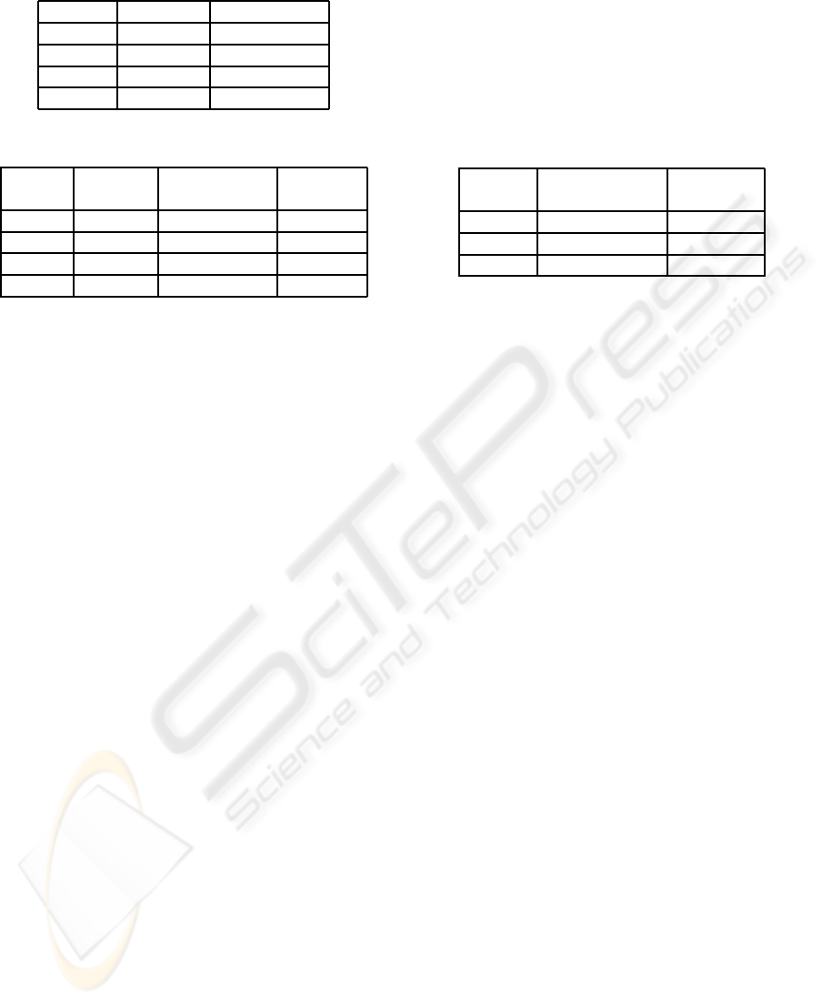
Table 1: Size and complexity of the test scenes.
Grid cells TIN triangles
Scene 1 400 3144
Scene 2 400 1563
Scene 3 1089 9872
Scene 4 5445 49360
Table 2: Performance results obtained with both proposals.
Triangles Inc. triang. HM based
generated based proposal proposal
Scene 1 186 442 fps 1356 fps
Scene 2 158 523 fps 1776 fps
Scene 3 444 308 fps 753 fps
Scene 4 2220 46 fps 132 fps
caves exist. For this example, vertex 4 is connected to
all vertices between 5 and 13, but not inside a nested
cavity, that is: {6, 7, 9, 10, 11}, and so on.
As explained in (B´oo et al., 2007; Amor and B´oo,
2008) the connectivity values generated for the coars-
est LOD can be employed for any other LOD, and
this unified representation may be employed for the
reconstruction of the convexification triangles associ-
ated with different levels of detail.
5 EXPERIMENTAL RESULTS
We have tested our two strategies employing a hy-
brid terrain visualization software that includes the
two tessellation algorithms.
Test computer hardware is a Intel Core 2 Duo
E6600 with 2 GB of RAM and a GeForce 8800GT
512 MB. We have used four different scenes in our
testing. The first three of them are formed by a regu-
lar grid partially covered by a TIN patch. The last one
is a synthetic model consisting of five copies of the
meshes present in scene 3. The number of grid cells
and TIN triangles of each scene is shown in Table 1.
The main results obtained with the two proposals
are summarized in Table 2. The number of triangles
generated to connect the differentrepresentation mod-
els (second column) is the same for the two methods.
This is coherent with the fact that the polygons to be
triangulated are the same for any method.
As is shown in the table, the HM based proposal
(fourth column) clearly outperforms the one based on
incremental randomized triangulation (third column).
HM method is, in the worst scenery, 2.44 times faster,
and it reaches the maximum difference in Scene 1,
where it is 3.40 times faster. This is a direct conse-
quence of using the preprocessed connectivity infor-
mation of the TIN boundary in the HM algorithm, to
generate the adaptive tessellation during run-time. As
the method based on the incremental randomized tri-
angulation does not perform any preprocessing of the
meshes, the tessellation is computed directly from the
selected vertices of the boundaries for each grid cell.
Table 3: Average compactness value of the triangles ob-
tained with both proposals.
Inc. triang. HM based
based proposal proposal
Scene 1 0,53 0,49
Scene 2 0,53 0,47
Scene 3 0,49 0,49
With respect to the quality of the triangulation,
high quality models can be generated with both meth-
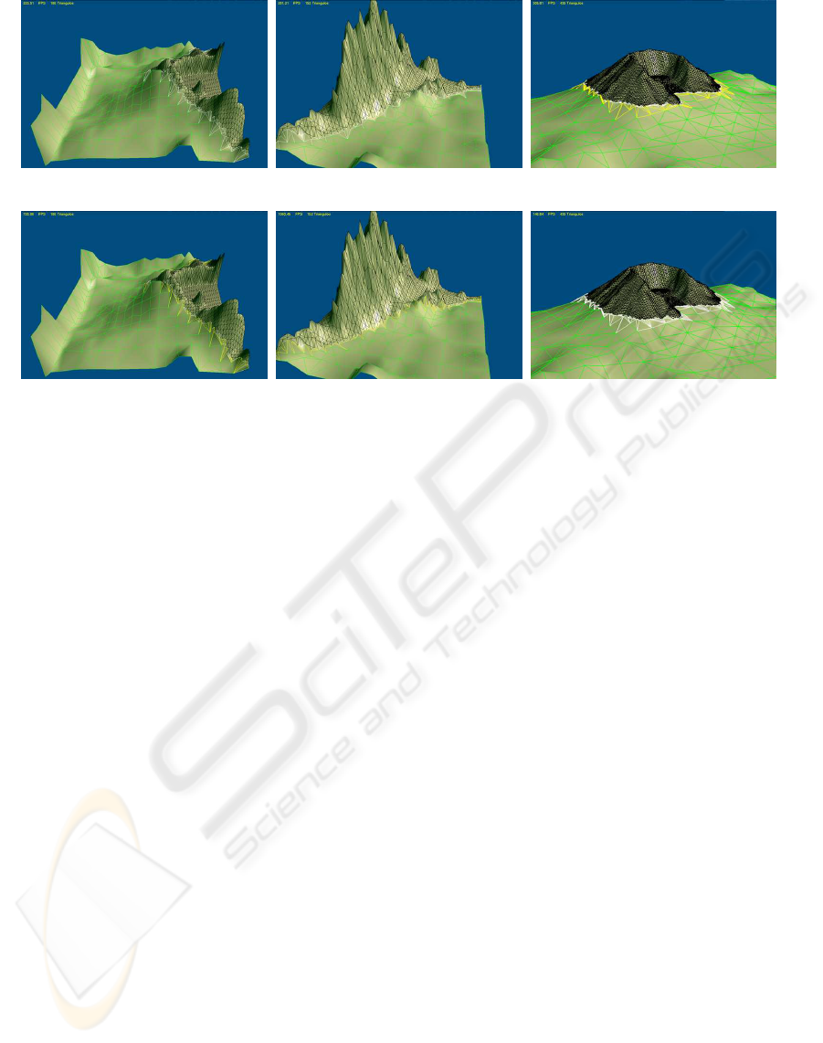
ods. An example of application is shown in Figure 4.
These are the resulting models when a detailed TIN
is applied to the scenes 1, 2 and 3. For both algo-
rithms the meshes are softly joined and the connec-
tions are performed locally to each cell. The triangles
generated are small and all the holes and cracks in the
borders are eliminated. Despite the fact that the tri-
angles generated with both methods are different, in
terms of visual quality they are in fact quite similar.
This fact is also shown in Table 3, where the average
compactness values obtained for the two methods are
presented. The compactness value (Gueziec, 1995) is
an indication of the triangles shape, usually employed
as a measure of quality, being zero for a degenerated
triangle and one for an equilateral triangle. As shown
in the table, triangulations obtained with both algo-
rithms are very similar. However, the high quality
results obtained in terms of speed with the HM al-
gorithm make it a better solution for hybrid terrain
rendering.
6 CONCLUSIONS
In this paper we have presented two different solu-
tions to the interactive visualization of hybrid terrain
meshes. Both methods are based on a process of
adaptive local tessellation between the boundaries of
a multiresolution grid model and a detailed TIN mesh.
Our first proposal is based on a standard polygon tri-
angulation algorithm (Seidel, 1991) and represents a
simple and direct approach to the problem: it con-
nects the models by performing a triangulation be-
tween the grid cell corners and the TIN boundary ver-
tices. The second proposal is based on the hardware
oriented HM algorithm (B´oo et al., 2007; Amor and
GRAPP 2009 - International Conference on Computer Graphics Theory and Applications
68
(a) (b) (c)
(d) (e) (f)
Figure 4: Adaptive tessellations generated by both proposals. Subfigures (a), (b) and (c) are generated by the proposal based
on the incremental randomized triangulation. Subfigures (c), (d) and (e) are generated by HM based proposal.
B´oo, 2008), adapted to a software implementation.
The results of our tests indicate that both methods
can obtain high quality meshes, without holes or any
other triangulation artifact, in real-time. In terms of
performance, however, HM based method runs sev-
eral times better than standard polygon triangulation
strategy. This important difference is caused by the
efficiently encoded, unified representation of the con-
vexification information in the TIN boundary for the
HM algorithm. This means that part of the triangles
are precomputed and decoded in run-time with simple
operations. Additionally, the remaining triangles are
generated through a straightforward procedure.
ACKNOWLEDGEMENTS
This work was partially supported by the Ministry
of Science and Technology of Spain under contract
TIN 2007-67537-C03, the Ministry of Education and
Science of Spain under the contract MEC TIN2004-
07797-C02, Xunta de Galicia under the contracts
08TIC0011206PR and Programa de consolidaci
´
on y
estructuraci
´
on de unidades de investigaci
´
on compe-
titivas, and also supported by the High Performance
Computing Galician Thematic Network (G-HPC).
REFERENCES
Amor, M. and B´oo, M. (2008). A New Architecture for
Efficient Hybrid Representation of Terrains. Journal
of Systems Architecture, 54(1-2):145–160.
B´oo, M., Amor, M., and D¨ollner, J. (2007). Unified Hybrid
Terrain Representation Based on Local Convexifica-
tions. Geoinformatica, 11(3):331–357.
Dykes, J., MacEachren, A., and Kraak, M.-J. (2005). Ex-
ploring Geovisualization. Elsevier.
Gueziec, A. (1995). Surface simplification with vari-
able tolerance. Second Annual Intl. Symp. on Med-
ical Robotics and Computer Assisted Surgery (MR-
CAS’95), pages 132–139.
Luebke, D., Reddy, M., Cohen, J., Varshney, A., Watson,
B., and Huebner, R. (2002). Level of Detail for 3D
Graphics. Computer Graphics and Geometric Model-
ing. Morgan Kaufmann Publishers.
Seidel, R. (1991). A Simple and Fast Incremental Random-
ized Algorithm for Computing Trapezoidal Decom-
positions and for Triangulating Polygons. Comput.
Geom. Theory Appl., 1(1):51–64.
VTerrain (2008). Virtual Terrain Project.
http://www.vterrain.org.
Yang, B., Shi, J. W., and Li, Q. (2005). An Integrated TIN
and Grid Method for Constructing Multi-resolution
Digital Terrain Models. Int. Journal of Geographical
Information Science, 19(10):1019–1038.
HYBRID TERRAIN VISUALIZATION BASED ON LOCAL TESSELLATIONS
69
