
MESOTHERAPY DEVICE FOR ESTHETIC APPLICATIONS
M. S. Martins
1
, V. M. G. Correia
2
, J. G. Rocha
3
Industrial Electronics Department, University of Minho, Campus de Azurém, 4800-058 Guimarães, Portugal
J. M. Cabral
Industrial Electronics Department, University of Minho, Campus de Azurém, 4800-058 Guimarães, Portugal
Keywords: Mesotherapy, Galvanic current, Step-Up circuit, Master-Slave Architecture, Microcontroller, H-Bridge,
PWM, CPU
Abstract: This article describes a complete system prototype to be used in aesthetic mesotherapy. The system is
composed by two main blocks: a Master block, whose chief component is a CPU, which provides the user
interface and a Slave block, implemented with a micro controller and a wave generator, which produces the
appropriated voltages and currents compatible with the mesotherapy treatments. The whole system is
powered by a 12V power supply and the output signal has a voltage that range between -54 V and 54 V. The
output signal is composed by the overlap of two frequencies: the first one is selected in the range from 1.2
kHz to 1.8 kHz and the second one is in the range from 0.07 Hz to 2 Hz. The system is being tested in
clinical environment with real patients showing very good promising results.
1 INTRODUCTION
Mesotherapy is a non-surgical cosmetic medicine
treatment that employs multiple injections of
pharmaceutical and homeopathic medications, plant
extracts, vitamins, and other ingredients into the
subcutaneous fat. Mesotherapy injections are
purported to target adipose fat cells, apparently by
inducing rupture and cell death among adipocytes.
(Tosti, 2007).
Mesotherapy has presented new opportunities in
aesthetic medicine because it is a non-evasive
treatment capable of reducing cellulite and weight
(Ward, 2002). Into these two capabilities are also
included protocols like Cellulite, Obesity, Facial and
Body Contouring. Besides these applications, the
mesotherapy can be applied in other treatments such
as acne, arthritis, sports injuries, ulcers, vein
treatments and rheumatology.
In this article we report some aspects of the
design and fabrication of a device prototype that
allows mesotherapic treatments. These treatments,
based on different layers of skin, are able to reach
9cm of depth (e.g. hypoderm or fat most affected
area).
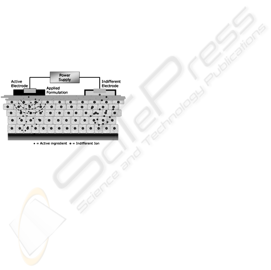
The basic working principle of the device
consists on a set of electrical pulses that are applied
on the skin surface, through two treatment
electrodes: a roll-on, used as active electrode, and a
glove, used as return electrode, originating two
reactions:
Expansion of the cell pores and epidermis
alignment, as shown in figure 1;
The electric field attracts the cream molecules
into the skin. The cream can be positively or
negatively charged, as shown in figure 2.
Figure 1: Transcellular and intercellular routes of
treatment cream through the lipid matrix.
256
Martins M., Correia V., Rocha J. and Cabral J. (2009).
MESOTHERAPY DEVICE FOR ESTHETIC APPLICATIONS.
In Proceedings of the International Conference on Biomedical Electronics and Devices, pages 256-261
DOI: 10.5220/0001551802560261
Copyright
c
SciTePress
The main objective of this project is the
development of a device prototype capable to
perform the treatments referred above. In order to do
that, it is necessary to:
Develop a programmable signal generator;
Due to practical issues the system supply
voltage cannot exceed 12V, while the output
signal may contain peaks that reach 54V;
Develop the appropriate safeguards to avoid
patients injuries;
Develop a user-friendly interface to be used by
technical personal without expertise on
electronics and informatics;
Develop a flexible system able to introduce
new types of treatments without hardware
upgrades;
Develop a system capable to report any type of
anomaly;
Develop a system able to work 24h/7day.
Figure 2: Electric field generated by the electrodes It is
visible the response of cream particles along the
hypoderm.
2 BACKGROUND
This project is being funded by several companies
and its main goal is to develop an hardware
prototype capable of performing mesotherapy,
reducing the technical expertise needed in treatments
handling. On the other hand, it is possible to expand
the functionalities of this prototype in order to
achieve other treatments in the area of
electrotherapy, without the need of adding new
hardware components.
With the support provided by ISAVE University
(ISAVE, 2008) we have been able to incorporate all
the information required to produce the proper
signals required to generate other therapy types of
currents:
Galvanic Currents;
Russian Electrical Simulation (Ward and
Shkuratova, 2002);
Transcutaneous Electrical Simulation;
Iontophoresis Current (Carter, 2003);
Pain-Free Currents (Johnson, 2003);
Electroforoporation Currents;
Thus, despite the development of this prototype
was targeted for aesthetic medicine, it can also
achieve other types of treatments since the platform
accepts other signals by changing only a few setup
parameters.
Electronic devices applied on esthetical medicine
must have a huge factor of accuracy and quality,
mostly the ones that are in direct contact with the
patient, leaving no space for errors.
In the past, all the options taken in the
development of these devices are mainly related
with the chosen materials and the methods that were
used to maximize perfection, quality, reliability and
performance.
In order to achieve the best results during a
treatment, the equipments must guaranty a clear and
precise signal output with a perfect repetition and
very low error tolerance.
In the esthetical medicine area there are different
types of treatments which can be held as a resource
of mesotherapy:
Anticellulite;
Located anticellulite;
Antistretch;
Antiflaccidity.
Each type of treatment needs a special signal
with a polarity, which may be positive or negative,
depending on the cream used. In all treatments the
applied signals obeyed to eq. 1:
SIGNAL = ((HF * LF) + LF)
(1)
where HF is the high frequency component,
whose value ranges between 1.2kHz and 1.8kHz,
and LF is the low frequency component, whose
frequency ranges from 0.07Hz to 2Hz (its period
ranges between 0.5 and 14 seconds).
Galvanic current is the base of this treatment. It
always circulates in the same direction (the voltage
is always positive or is always negative), once each
cream has its own polarity. Therefore the system
must guarantee this characteristic for the generated
voltage, that is, the system must follow the
algorithm:
Positive Polarity:
If ((HF * LF) + LF) < 0
MESOTHERAPY DEVICE FOR ESTHETIC APPLICATIONS
257
then SIGNAL=0
Else
SIGNAL = (HF * LF) + LF
Negative Polarity:
If ((HF * LF) + LF) > 0
then SIGNAL=0
Else
SIGNAL = (HF * LF) + LF
3 SYSTEM ARCHITECTURE
The general system architecture proposed in this
paper is a master-slave structure since there are two
control units: a high-level control unit (master) and a
low-level control unit (slave).
The high-level control unit or central processing
unit (CPU) is responsible for supporting the user
interface: exchanging and processing the necessary
information between the user and the low-level
control unit. The low-level control unit, whose main
component is a micro controller, is responsible to
convert digital data, received from the high-level, to
analogical signals that are applied directly to the
patient skin, through the connection devices.
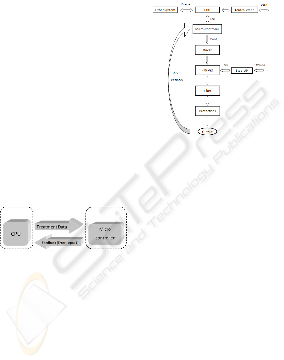
Figure 3 shows the system architecture.
Maste
r
Slave
Figure 3: System architecture. The CPU operates as
master and the micro controller operates as slave. The
micro controller functionalities are controlled by the CPU.
Despite the system is of master-slave type, a
feedback from the output to the micro controller is
used in order to allow the detection of some
malfunctions.
The Master block is composed by a processor
unit, a touch-screen and an Ethernet interface, while
the Slave block is constituted by a micro controller,
a step-up converter, a driver, an H-bridge, a filter
and the patient’s protection circuit. Both blocks
communicate by means of an USB interface.
The following paragraphs describe, in detail, the
most important functions shown in figure 4.
Figure 4: Block Diagram of the device internal structure
and the links between the various sub-systems.
The CPU is the head of the system, responsible
for gather all the data, coming from the user-
interface console, process it and calculate the
appropriated coefficient vector that will be used by
the micro controller to produce the corresponding
output signal with a PWM (Pulse Width
Modulation).
If we consider that the technical personal do not
have expertise in informatics and electronics
technologies, it is important to provide an intuitive
graphical interface. For this purpose, it was used a
touch-screen monitor to operate the device in an
intuitive way. The programming language used was
C++, associated to an Open GL platform in order to
satisfy several requirements, namely the real time
operation, the support for micro controller systems
and the attainment of the maximum graphic
potentialities of the system.
It is important to refer that this platform is based
on a Linux operating system, due its great
potentialities for real time operation associated with
the advantage that it is a free software, making
easier and cheaper the system commercialization.
Another particular feature is the system
dynamism, which enables firmware upgrades and
interconnection with other devices in order to allow
a huge range of treatments.
All interconnections between CPU and other
functional blocks are bidirectional, allowing a
continuous feedback that enable instantaneous
detection of any anomaly.
BIODEVICES 2009 - International Conference on Biomedical Electronics and Devices
258
The micro controller is responsible for
assembling the information, sent by the CPU, in
order to drive the H-Bridge. It calculates the PWM
ON / OFF times, generating the desired signal to the
system output.
The micro controller uses an 8MHz crystal. In
order to generate a PWM signal that does not reach
frequencies higher than 30kHz, the sampling
frequency used by the micro controller is about 17
times higher than the frequency of the output signal
to ensure a low ripple at the filter output.
An AT90USB1287 low-power CMOS 8-bit
micro controller was used (Johnson and Tabasam,
2003), based on the AVR with 64/128K bytes of ISP
Flash and an USB device controller with full speed
and low speed data transfer support, enhanced RISC
architecture. By executing powerful instructions in a
single clock cycle, the AT90USB1287 achieves
throughputs approaching 1MIPS per MHz allowing
the system designer to optimize power consumption
versus processing speed.
The interface between master and slave blocks is
achieved by means of a USB connection due to is
large bandwidth and Plug and Play interoperability.
A full-duplex low speed (1.5Mbit/s) data rate
connection is used that guarantees up to 512kbit/s of
bandwidth in each direction.
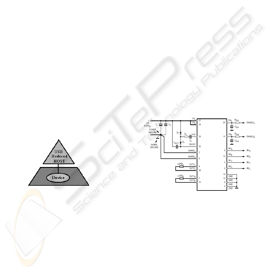
The Bus topology used is the Reduced Host
Topology showed in figure 5 (Atmel, 2007).
Figure 5: Reduced Host Topology. A reduced host
controller has a unique USB port and does not handle full
USB tree with hub. It means that a reduced host controller
is designed to handle a unique point-to-point connection
with an unique USB device.
Its main characteristics are:
USB Host:
There is only one host in any USB system, and
it operates as the “master” of the USB bus;
The USB interface to the host system is referred
to as the Host Controller.
USB Device:
An USB device operates as a slave node on the
USB bus;
Thanks to the USB hub (that also operates as an
USB device) up to 127 devices can be
connected on the USB bus. Each device is
uniquely identified by a device address.
It would be only necessary to implement a more
elaborated connection topology if the micro
controller interacts with more than one device
because it would be necessary to guarantee that it
communicates with the correct device. As this
system is composed by just one device, the use of
the simplified topology facilitates the
implementation of the connection between the CPU
and the micro controller.
The micro controller output signal produces a
peak voltage of 3.3V. To manage an effective
treatment it is necessary to amplify this signal to
higher levels, such as 54V. To carry out this task it
was implemented an H-bridge with two quadrants,
allowing the change of the signal output polarity
according to the corresponding treatment. The H-
Bridge was implemented by means of L6225 DMOS
Dual Full Bridge chip which combines isolated
DMOS Power Transistors with CMOS and bipolar
circuits on the same chip (STMicroelectronics,
2007). Figure 6 shows the schematic diagram of this
circuit.
Figure 6: H-Bridge circuit based on BCD technology.
Combines isolated DMOS Power Transistors with CMOS
and bipolar circuits on the same chip.
The signal output is a sum of two components: a
low frequency of 0.07Hz (Period = 14s) and a high
frequency of 1.8kHz. A low-pass active filter, with a
Q factor of 2, and a cut-off frequency of 2kHz were
used. Thus the filter output no longer presents the
high frequency components, produced by the PWM
modulator, and all variations of the sign are
smoothed. Figure 7 shows the output waveform of
the PWM modulator. Figure 8 depicts a time
expansion between B1 and B2 bars of figure 7.
MESOTHERAPY DEVICE FOR ESTHETIC APPLICATIONS
259
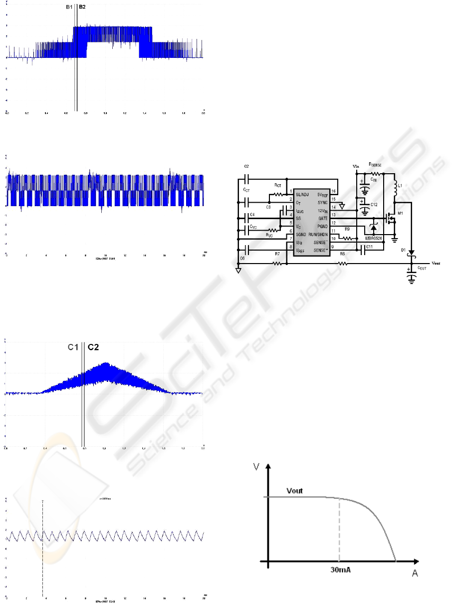
Figure 7: Signal obtained at the output of the H-Bridge
circuit, with 2s in time axis and 5V in voltage axis.
Figure 8: Signal of figure 7, expanded with 20ms between
B1 and B2 bars.
Figure 9 shows the low pass filter response. Figure
10 depicts a time expansion between C1 and C2 bars
of figure 9
.
Figure 9: Signal obtained at the system output. It
corresponds to the signal of Fig. 8 be low-pass filtered,
with 2s in time axis and 5V in voltage axis.
Figure 10: Signal Signal of figure 9, expanded with 20ms
between B1 and B2 bars.
Standard requirements (RSIUEE, 1974),
imposed on medical equipment, does not allow that
the power system, responsible for generating
treatment signals, have input voltages higher than
12V. Nevertheless, to obtain the expected results,
the signal output must produce peaks of 54V. This
task is achieved by means of a step-up circuit which
provides up to 54V linear voltage with small ripple
and 500mA of maximum current. In the present
application the current can not exceed 50mA. The
step-up circuit is implemented with the LT1680
(Linear Technology, 2007) whose schematic
diagram is shown in figure 11.
Figure 11: Step-Up circuit. High power, current mode
switching power supply controller optimized for boost
topologies. The IC drives an N-channel MOSFET switch
for DC/DC converter up to 60V output.
All equipment must obey to security rules
imposed by responsible entities. Therefore, in
addition to the main objective, that is, the
mesotherapic equipment development, we have also
to ensure the safety of the patient. In this way, it was
introduced a current limiter before the signal output.
When the current reaches higher values than 30mA,
the circuit output voltage is lowered, as it is shown
in figure 12.
Figure 12: Output voltage versus current. For currents
above 30mA the system protection responds by reducing
the output voltage.
BIODEVICES 2009 - International Conference on Biomedical Electronics and Devices
260
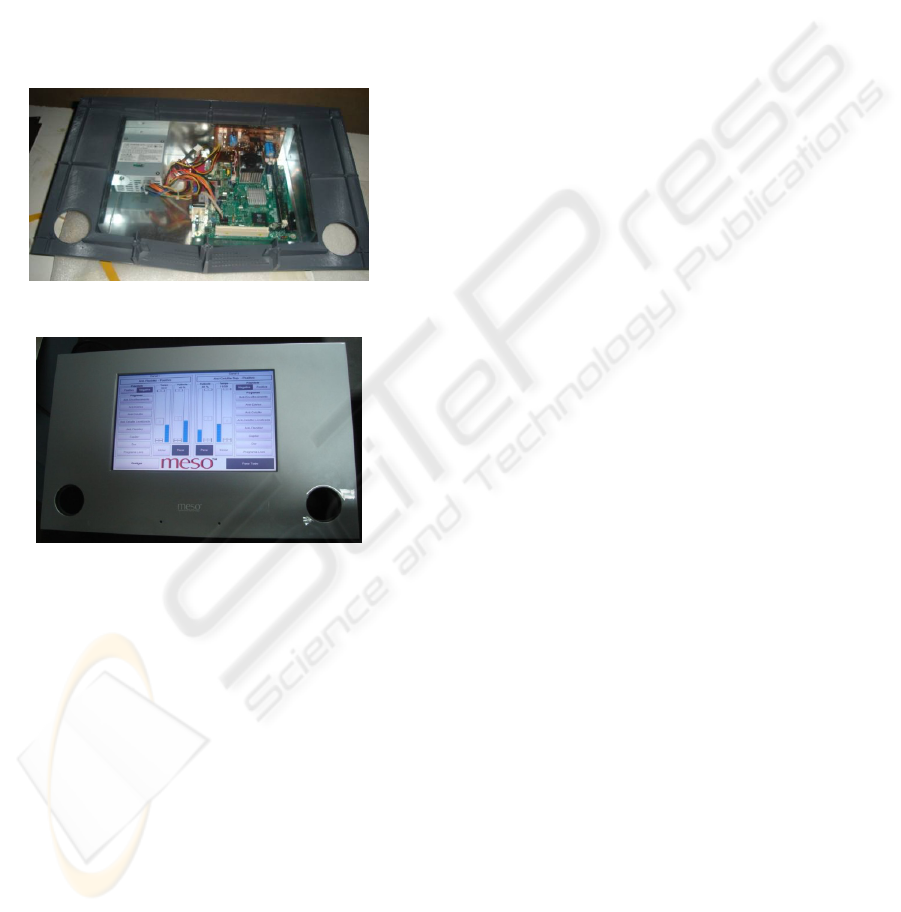
4 PROTOTYPE
To conduct the necessary system tests, a prototype
was built where the methodology described in this
article was implemented. This prototype is now
being used in the aesthetics mesotherapy treatments
in order to get a functionality and efficiency
diagnosis of the device. Therefore, it is necessary
that this prototype show the full potentialities of the
system but also show simple and functional user-
interface to simplify the use by the technical
personal. Figures 13 and 14 show some pictures of
the prototype.
Figure 13: Device internal circuits.
Figure 14: Device external appearance.
5 CONCLUSIONS
This article described a complete system prototype
for use in aesthetic mesotherapy. The system is
composed by a master-slave architecture in which
the master block is based on a CPU and the slave
block is based on a micro controller. The first
system prototype is already tested and fabricated in
laboratory conditions with performances that
correspond to the expected ones. It was also tested in
a clinical environment, with real patients. The results
of these tests are more or less subjective once consist
on the opinion of the technicians and patients, but
almost all consider the performance of the prototype
as good or very good. As a future work, the
prototype software will be adapted to perform
lymphatic draining or muscle stimulation treatments.
ACKNOWLEDGEMENTS
The authors would like to thank Doctor Cláudio
Javier Martinez Leon, who helps the authors in
understanding aesthetics mesotherapy treatments
fundamentals.
REFERENCES
A. Tosti, M. Pia De Padova, "Atlas of Mesotherapy in
Skin Rejuvenation", Informa Healthcare, United
Kingdom 1 September 2007.
ISAVE Website, “http://www.isave.edu.pt”.
Carter R. Anderson, Russell L Morris, Stephen D Boeh,
Peter C Panus, Walter L Sembrowich, “Effects of
Iontophoresis Current Magnitude and Duration on
Dexamethasone Deposition and Localized Drug
Retention”, Physical Therapy. Volume 83. Number 2.
February 2003.
Charles Godbout, Jérôme Frenette, “Periodic Direct
Current Does Not Promote Wound Closure in an In
Vitro Dynamic Model of Cell Migration”, Physical
Therapy. Volume 86. Number 1. January 2006.
Mark I. Johnson, Ghazala Tabasam, “An Investigation
Into the Analgesic Effects of Interferential Currents
and Transcutaneous Electrical Nerve Stimulation on
Experimentally Induced Ischemic Pain in Otherwise
Pain-Free Volunteers”, Physical Therapy. Volume 83.
Number 3. March 2003.
Alex R. Ward, Nataliya Shkuratova, “Russian Electrical
Stimulation”, Physical Therapy. Volume 82. Number
10. October 2002.
S. Madhere, "Aesthetic Mesotherapy and Injection
Lipolysis in Clinical Practice", Taylor & Francis Ltd,
United Kingdom 15 June 2006.
Atmel Corporation 2007 - Microcontroller at90USB1287,
http://www.atmel.com/dyn/resources/prod_documents
/doc7593.pdf.
STMicroelectronics 2007 - DMOS Dual Full Bridge
Driver L6225, http://www.st.com/stonline/products/
literature/ds/9451.pdf.
Decreto-Lei nº 740/74 Artº 598º Protecção contra
contactos indirectos, Regulamento de Segurança de
Instalações de Utilização de Energia Eléctrica
(RSIUEE), December 1974, Portugal.
Linear Technology 2007 - High Power DC/DC Step-Up
Controller LT1680,
http://www.linear.com/pc/downloadDocument.do?navId=
H0,C1,C1003,C1042,C1031,C1115,P1597,D1509
MESOTHERAPY DEVICE FOR ESTHETIC APPLICATIONS
261
