
DESIGN OF A BIO-INSPIRED WEARABLE EXOSKELETON
FOR APPLICATIONS IN ROBOTICS
Michele Folgheraiter, Bertold Bongardt, Jan Albiez and Frank Kirchner
German Research Center for Artificial Intelligence DFKI Bremen
Robotics Lab Robert-Hooke-Strae 5D-28359 Bremen, Germany
Keywords:
Haptic Interface, Bio-Inspired Device, Biorobotics, Exoskeleton.
Abstract:
In this paper we explain the methodology we adopted to design the kinematics structure of a multi-contact
points haptic interface. We based our concept on the analysis of the human arm anatomy and kinematics with
the intend to synthesize a system that will be able to interface with the human limb in a very natural way. We
proposed a simplified kinematic model of the human arm using a notation coming from the robotics field. To
find out the best kinematics architecture we employed real movement data, measured from a human subject,
and integrated them with the kinematic model of the exoskeleton , this allow us to test the system before its
construction and to formalize specific requirements. We also implemented and tested a first passive version of
the shoulder joint.
1 INTRODUCTION
In this paper a bio-inspired design approach to syn-
thesize the kinematics structure of a haptic interface is
introduced. The system presented is mainly intended
for applications in the field of the tele-robotics sys-
tems; nevertheless can also be effectively employed
as a sophisticated haptic interface during the interac-
tion with a virtual environment or during a training or
rehabilitation session.
In interaction with a human an exoskeleton can
provide two main functionalities: First, it can be used
as an assistive device, e.g in physiotherapy an ex-
oskeleton can be adopted for movement enhancement
(Gupta et al., 2008) (Carignan et al., 2005), in other
scenarios it can be used for performance augmenta-
tion (Dollar and Herr, 2008).
Second, an exoskeleton can be used as an input
device, enabling a human operator to manipulate ei-
ther a virtual or a real target system. The latter use-
case – which is called teleoperation surrenders in any
situation where work has to be done in regions, in
which it is unfavorable or even impossible to work as
a human. Possible applications for teleoperation oc-
cur in telesurgery (Bar-Cohen et al., 2001), aerospace
(Schiele and Visentin, 2003) and underwater (Kwon
et al., 2000).
The primary aim of an intuitive teleoperation is to
allow a human operator to see and feel the remote en-
vironment, as a secondary aim he further should be
able to attribute himself with the target robot (IJssel-
steijn et al., 2006). A general overview about the topic
of teleoperation is given in (Hokayem and Spong,
2006).
In case of teleoperation an exoskeleton acts as an
human-robot haptic interface which is “nothing but
a bidirectional mechanical transducer”(Hayward and
Astley, 1996). Ciriteria for the quality of haptic feed-
back are given in (Hayward and Astley, 1996), com-
parative studies are are presented in (Griffin et al.,
2005) or (Yu, 2003).
The hardware of existing constructions of ex-
oskeletons differ in their degree of activity: On the
one hand pure passive devices were developed by
(Song et al., 2005) and (Chen et al., 2007, ZJUESA).
On the other hand empowering exoskeletons were
built up, see (Dollar and Herr, 2008). Between
these extrema one finds exoskeletons acting as force-
reflecting controlling devices. These can be further
categorized into solutions which are fixed to an exter-
nal basis (Mistry et al., 2005) and (Perry et al., 2007)
and those remaining wearable. The latter is described
by the study in (Kim et al., 2001).
In the next following section we introduce the
model used during the design process, we also
presents some results from the study we conducted
on a real human subject in order to analyse the impor-
tance of the Clavicle-Scapula articulation during the
414
Folgheraiter M., Bongardt B., Albiez J. and Kirchner F. (2009).
DESIGN OF A BIO-INSPIRED WEARABLE EXOSKELETON FOR APPLICATIONS IN ROBOTICS.
In Proceedings of the International Conference on Biomedical Electronics and Devices, pages 414-421
DOI: 10.5220/0001550704140421
Copyright
c
SciTePress
shoulder movement. Section 3 deals with the kine-
matic model of the exoskeleton, in particular here we
reported only the system that is supposed to be cou-
pled with the shoulder of the user. In section 4 we pro-
pose a possible design for the exoskeleton and present
some preliminary results. Finally section 5 draws out
the conclusions and the future developments.
2 HUMAN ARM STUDY
AND KINEMATIC MODEL
The Human Arm represents one of the most advanced
manipulation system we can find in nature. It is the
product of an evolutionary process lasted 3.7 billion
years (origin of life on the Earth). Its kinematics is
defined by the configuration of different bones and
articulations, these elements represent the structural
components of the limb. Grossly we can divide the
arm in two different parts: the upper arm and the fore-
arm. The upper arm is represented by the segment that
goes from the shoulder to the elbow, the forearm the
segment that goes from the elbow to the hand.
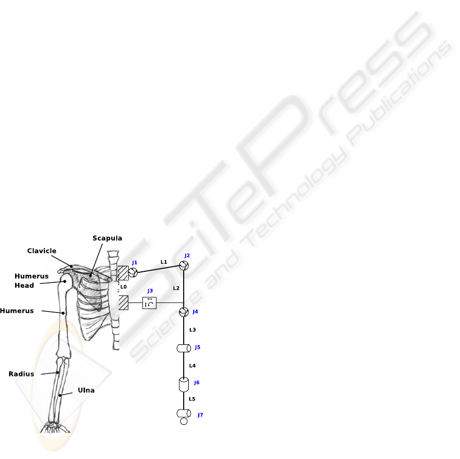
Starting from the sternum (see picture 1), that for
us represent the reference base, and moving toward to
the distal part of the limb, we can encounter the fol-
lowing bones : Clavicle, Scapula, Humerus, Radius,
Ulna, Carpus Bones, Metacarpus Bones, Phalanxes.
Figure 1: Representation of the skeleton of the human
arm and its 10 DOF simplified kinematics model using a
robotics notation.
In literature we can find different kinematic mod-
els for the human arm (Klopcar and Lenarcic, 2005),
(Schiele and van der Helm, 2006), each one oriented
to describe certain aspects rather than the others; As
in (Schiele and van der Helm, 2006), to represent the
kinematic model of the human arm, we used a no-
tation related with the robotics field this in order to
couple it more easily with the kinematic model of the
exoskeleton. Of course we introduced numerous sim-
plifications and assumed the articulations like joints
with a well defined geometry, nevertheless we think
that for our study this fits well.
The model formalized is represented in figure 1
(right side), again we can separate the kinematic ar-
chitecture in two different parts: Shoulder Kinemat-
ics, Arm Kinematics. The shoulder Kinematics is
composed by four joints, three spherical (3DOF) and
one planar. More in detail the planar joint can be de-
composed in two prismatic and one rotational joint,
however in this first representationwe preferredto use
a compact notation. It also should be noted that the
shoulder kinematics can be further separated in two
other parts: one that is a closed kinematic chain, and
the other that is an open kinematic chain represented
by a spherical joint located in the proximal part of the
upper arm link. The closed chain is formed by three
links and three joints, joint-1 (spherical) is located be-
tween link-0 (the link with the inertia reference sys-
tem) and link-1, joint-2 (spherical) is located between
link-1 and link-2, and finally joint-3 (planar) close the
kinematics chain connecting link-2 and link-0.
The first consideration we can do on this kine-
matic chain is about the overall mobility. The three
joints have a total of 9 DOFs, however because of its
parallel nature there are some constrains that limit the
mobility. We can define q as the configuration vari-
able, this is a vector with m components (q ∈ R
m
)
that define unambiguously the position and the ori-
entation of the all rigid bodies that compose the kine-
matic chain. We consider in this case only minimal
configurations, this means that is not possible define
unambiguously the system with less than m scalars.
Given the kinematic chain we can calculate the
dimension for q applying the Kutzbach-Gr¨ubler for-
mula (Zhao et al., 2004) :
m = 6(n− g− 1) +
g
∑
i=1
f
i
(1)
where n is the number of links present in the kine-
matic chain, g is the number of joints, and f
i
is the
number of degrees of freedom for the i
th
joint. If we
apply this equation to our specific case we obtain:
m = 6(3− 3− 1) +
3
∑
i=1
f
i
= −6+ 9 = 3 (2)
This mean that this chain has overall three de-
grees of freedom, therefore to define unambiguously
DESIGN OF A BIO-INSPIRED WEARABLE EXOSKELETON FOR APPLICATIONS IN ROBOTICS
415
its kinematic configuration we can just define only
three scalars. The model differs from (Schiele and
van der Helm, 2006) for the presence of an addi-
tional DOF that allows to represents better the human
anatomy. The question that arise now is: which joints
variables we have to chose to define the configura-
tion of the shoulder, in theory it is possible to chose
just three variables from the nine we have. In practice
we will see that there are some choices that are bet-
ter than others, this especially if we need to measure
these quantities in a real system.
Starting from the joint-4 the human arm can be
represent as a open kinematic chain. As we can
see from picture 1 joint-4 (lower part of the shoul-
der) connects link-2 to link-3. This joint has a total
of three DOF and allows movements of extension-
flexion, adduction-abduction and rotation around the
upper arm axis.
Moving toward the distal part of this model we
encounter joint-5 (the elbow) that connect link-3 with
link4, this is a one DOF rotational joint that allow
forearm flexion and extension. Finally we have joint-
6 (first degrees of freedom for the wrist) that connect
link-4 with link-5. In comparison with the human arm
anatomy this represent a simplification, indeed in hu-
man beings it is a complex movement of both radio
and ulna bones that allows the wrist rotation. Any-
how in a first approximation this simplification is not
so critical for our purposes. A more accurate model
will be formalized in the case the results obtained will
be not satisfactory.
In picture 1 we represented also the other joint for
the wrist, joint-7, this has a total of two degrees of
freedom that in the human arm allow the wrist flexion-
extension and adduction-abduction. At the moment
the hand kinematics is not considered in our study.
2.1 Analysis of the Arm Movements
In order to better understand the kinematic of the hu-
man Arm, and to start the validation of the proposed
model, we conducted a first experiment where we ac-
quired the trajectories of different points of interest
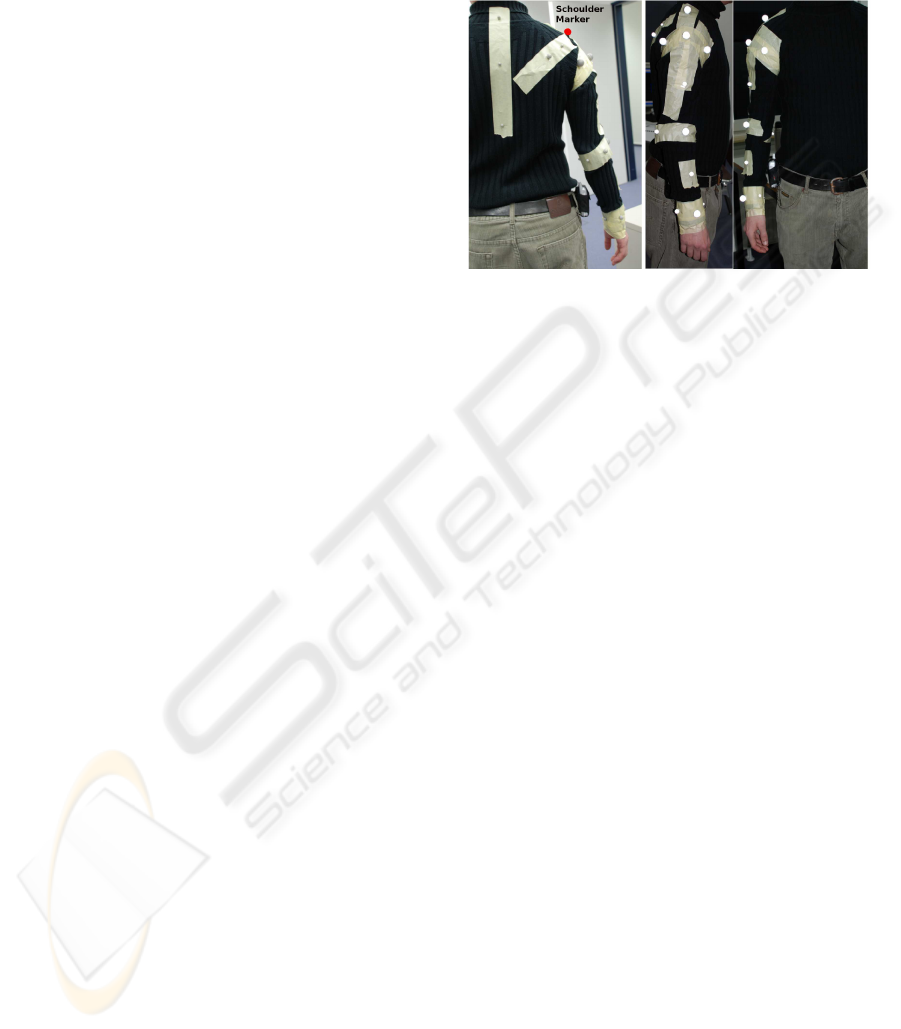
located on the surface of the Arm. We applied a total
of 19 markers (see picture 2) on a male subject (height
1.7m.) 3 along the spinal cords, 3 on the scapula, 1
on the top of the shoulder, 3 for the shoulder ring, 1
in the middle of the upper arm, 3 in the elbow ring , 1
in the middle of the forearm, and 4 in the wrist ring.
We wanted to acquire the trajectories of all the parts
of the Arm that are involved during the performance
of an arbitrary movement. In the first experiment we
asked the subject to perform a movement of flexion
and extension of the shoulder. The rotation was rela-
tive to an hypothetical axes orthogonal to the sagittal
plane, of course due to the complex kinematic of the
shoulder this axes is not fixed, but changes according
with the shoulder movements.
Figure 2: 19 Markers were fixed on the surface of the sub-
ject’s arm.
The Experiment where done using a commercial
motion tracking system by Qualysis
r
, we employed
the version with three cameras.
We chose an arrangement in order to avoid as
much as possible the landmarks occlusion during the
planned movement.
During the acquisition subject was located near
the reference system, and was asked to perform the
movement of the arm trying to keep fixed as much as
possible the rest of the body.
After data acquisition and post-processing, it was
possible to analyze the results visually, and to ex-
port the data in text format for a further elabora-
tion by Matlab. The analysis of the movement by
the QualysisTrackManager
r
showed many interest-
ing features and behaviors. We noted that from the
first phase of the extension movement all the bones
of the upper shoulder are involved. We could recog-
nize this by observing the trajectory of the markers
located on the top of the shoulder, and in proximity of
the scapula (figure 3a ).
This means that it is very difficult to separate the
movement of the lower shoulder from the movement
of the upper shoulder, it turns out that we need to con-
sider the entire shoulder kinematics from the begin-
ning of the exoskeleton design. In picture 3 (b) we
can see the trajectories followed by the markers for
quite the complete extension movement (90%), it ap-
pears that many of them have a circular pattern, this
is natural if we think at the kinematic structure of the
human shoulder.
BIODEVICES 2009 - International Conference on Biomedical Electronics and Devices
416
a. b.
Figure 3: (a)First part of the movement, it possible to note
that the markers on the top of the shoulder start to move (b)
Trajectories followed by the markers during the 90% of the
extension movement.
3 THE EXOSKELETON
KINEMATIC
The exoskeleton kinematics is strongly influenced
both by the human arm anatomy and the perfor-
mances we want to reach. The central idea is to try
to restrict the mobility of the user’s arm as less as
possible when he is wearing the exoskeleton. Other
desiderable requirements for the overall system are:
• Lightweight construction
• A system easily wearable
• Multi-contact points haptic feedback
• Modular design
All these goals are important to synthesize the
kinematic structure for the exoskeleton, but for an ini-
tial analysis, the overall mobility constrains and the
necessity to have multi-contact point haptic interface,
represent our most relevant aims.
If we want to reduce the user’s mobility limita-
tions due to the exoskeleton we can fix the following
kinematic requirements:
• The upper arm coupled with the upper part of the
exoskeleton should have a total of 3 DOFs
• The forearm coupled with the lower part of the
exoskeleton should have a total of 2 DOFs
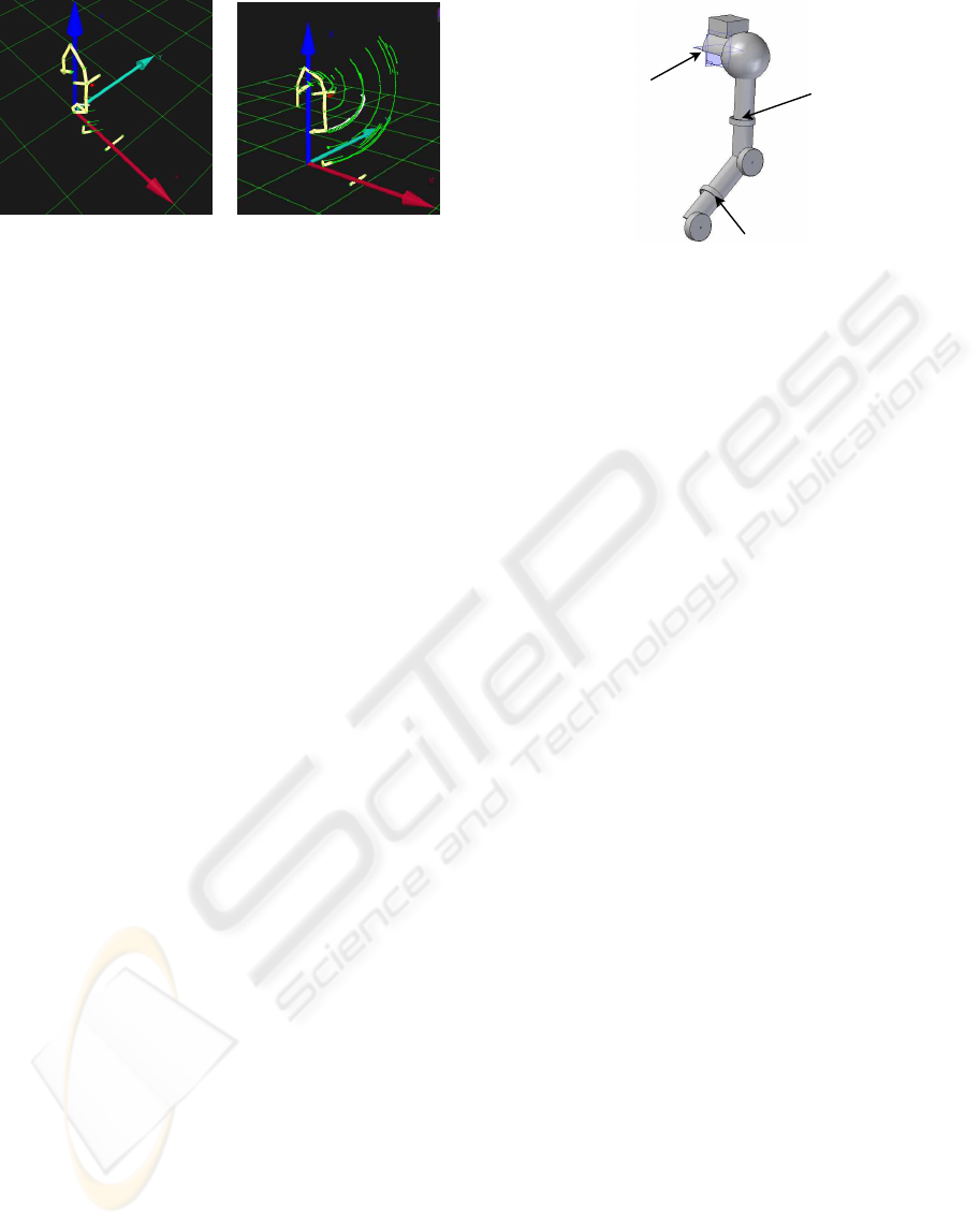
In order to provide the user a broad haptic feed-
back, our exoskeleton will transmit forces and torques
via multiple contact points. One of these we have
already defined locating the exoskeleton-shoulder on
the user-shoulder, the other will be located in the mid-
dle of the user upper arm and the last one in the middle
of the user forearm. This locations are optimal in the
sense that they reduce the interference with the hu-
man articulation during the user movements. One can
see these three different contact-points represented in
figure 4.
Contact Point 1
Contact Point 2
Contact Point 3
Figure 4: Contact points between the exoskeleton and the
human arm.
3.1 Coupling the Exoskeleton with the
Human Arm
It is important now to do some considerations about
the overall kinematics that we obtain combining the
arm with the exoskeleton. This will also help us to
setup how many degrees of freedoms are required for
the exoskeleton.
The next paragraph will concentrate only on the
exoskeleton’s kinematics that deals with the shoulder
and the upper arm of the user, even if we have al-
ready started to extend the analysis also for the fore-
arm. This omission is also justifies by the fact that at
the moment we tested on a human subject only this
part of the exoskeleton.
3.1.1 The Upper Shoulder Joint
Here we the term joint we want to refer to the en-
tire kinematic structure for the mechanical system that
is charged to deal with the upper shoulder (clavicle-
scapula articulation). How many degrees of freedom
should have this joint? From the motion analysis on
the human arm it comes up that the upper shoulder
has a total of 3DOF, but again in order to design the
exoskeleton joint it is necessary to do some assump-
tions about its kinematics. A possible configuration
is presented in figure 5 (upper part) here we can see
that now we have a complex structure with different
closed paths.
In order to study the system we can do a first sim-
plification substituting the upper shoulder kinematic
with a single joint with 3 DOF, in this case we have a
simplified structure showed in figure 6.
Now it is possible to apply the theory in order to
find the overall mobility of this configuration, we can
calculate the number of DOF’s with equation 3.
m = 6(n− g−1) +
g
∑
i=1
f
i
= 6(5− 5−1)+ 9 = 3 (3)
DESIGN OF A BIO-INSPIRED WEARABLE EXOSKELETON FOR APPLICATIONS IN ROBOTICS
417
3DOF
3DOF
J 1
es
J 2
es
J 3
es
3DOF
L 0
s
L 0
s
L 0
es
L 2
es
L 3
es
Figure 5: Closed kinematic chain formed between the ex-
oskeleton shoulder joint and the upper shoulder kinematic
chain.
2DOF
3DOF
L 0
s
L 0
es
J 1
es
L 2
es
J 3
es
L 1
es
J 2
es
2DOF
1DOF
L 2
s
L 1
s
1DOF
Figure 6: Equivalent model.
As is represented in figure 6 the exoskeleton has
a total of 6 DOF; because we need to actuate a 3
DOF kinematic chain, it means that only 3 of the 6
DOF must be actuated and sensed. From a mechan-
ical point of view it is more suitable to actuate the
joints (J
es
1 and J
es
2) that is near to the barycenter of
the body, in this way the actuation system is not re-
quired to move also the weigh of the actuators itself,
this come clear if you think to the torque that can ex-
ercise a weight localized near the joint J
es
3 to the joint
J
es
1.
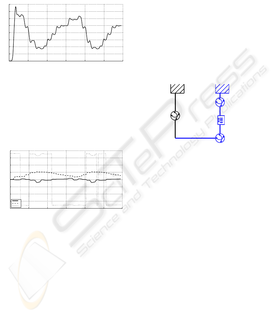
3.1.2 Model Simulations
To fix some specifications for the actuation system of
the exoskeleton we formilized a kinematic-dynamic
model of the exoskeleton shoulder-joint using the
toolbox SimMechanics in Matlab-Simulink environ-
ment. The system is composed of a spherical joint
and a prismatic joint (see picture 7).
The initial point for the exoskeleton joint is coin-
cident with the middle landmark along the spinal cord
(see section 2.1).
In order to analyze the motion in a realistic way,
we constraint the point P (see picture 7 ) to lie on a
trajectory. We imposed as a trajectory the one we ob-
tained from the motion analysis of the human arm per-
forming an extension-flexion movement of the shoul-
der (underlined Marker in picture 2). To constrain
the point on the desired trajectory we apply a force
field directly on the point that was generated using a
MIMO (Multi Input Multi output) PID controller, pa-
Figure 7: Simulation for the Shoulder Joint, measures in
meters.
rameters of this controller were not optimized because
we wanted only to perform a kinematical test of the
system. The PID in question can be represented using
a diagonal matrix:
P=0.4,I=0.1,D=0.3 0 0
0 P=0.4,I=0.1,D=0.3 0
0 0 P=0.4,I=0.1,D=0.3
!
This means that only the position error along the
X-axis will effect the X-component of the force, and
the same for error along Y- and Z-axis. The results of
this simulation is reported in picture 8, as it possible
to see the force field generated is able to constrain
the point trajectory (thicker line) near the reference
trajectory (thin line).
0.02
0.04
0.06
0.08
0.1
0.12
0.14
0.16
0.18
0.2
−0.1
−0.08
−0.06
−0.04
−0.02
0.55
0.6
0.65
0.7
0.75
m
m
m
Figure 8: The trajectory followed (thicker line) by the point
located on the upper shoulder, the thin line is the reference
trajectory acquired from a human subject.
Once we are sure that point P is well constrained
we can monitoring the position of each joint of the ex-
oskeleton in order to evaluate the range of its move-
ment, this is very useful to obtain same specifications
for the design of the real system. In the graph of pic-
ture 9 we can see the linear position of the prismatic
joint, how it is possible to note the range for this sub-
ject is about 0.08m (8cm). Of course it is necessary to
BIODEVICES 2009 - International Conference on Biomedical Electronics and Devices
418
perform this analysis on different subjects if we want
to have a system that can adapt to different arm sizes,
this will be the subject of future work.
0 50 100 150 200 250 300
0
0.02
0.04
0.06
0.08
0.1
0.12
0.14
0.16
Sample
Position [mm]
Figure 9: Range for the prismatic joint.
Figure 10 reports the angular positions of the
spherical joint in convention of the Euler angles (roll,
pitch and yaw). Therefore if we want to obtain the an-
gular position of the exoskeleton we should do in se-
quence three rotations along X,Y and Z respectively.
Again we can evaluate the excursion for each sin-
gle angle, from figure 10 we can see that roll range is
about 30
o
, the pitch 50
o
and finally the yaw 15
o
.
0 50 100 150 200 250 300
−200
−150
−100
−50
0
50
100
150
200
Sample
Angular position [Degrees]
X
Y
Z
Figure 10: The three Euler Angles for the spherical joint.
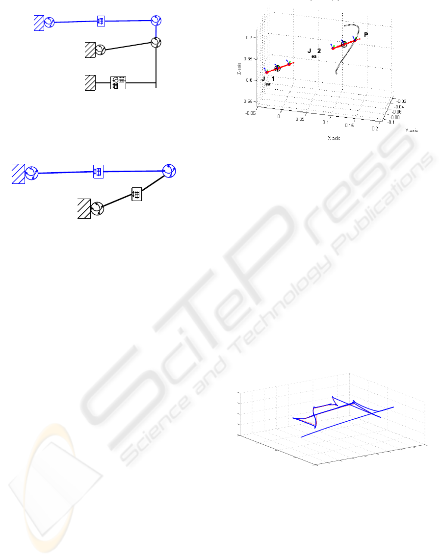
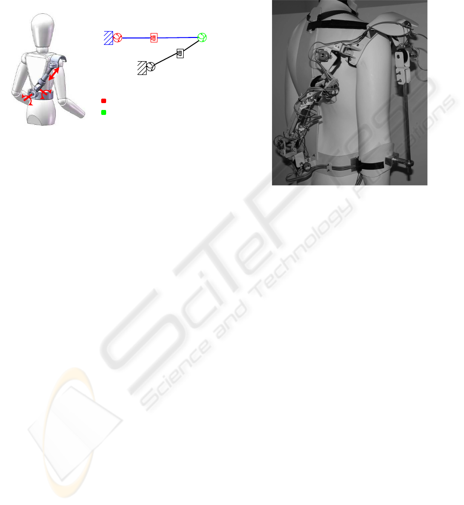
3.1.3 Lower Shoulder Joint
Considering the lower shoulder (upper arm) com-
bined with the upper part of the exoskeleton (figure
11) one can identify a closed kinematic chain. It
starts at the link L
a
0, crosses join J
a
1 (the user shoul-
der), goes toward the contact point one (where the ex-
oskeleton is fixed with the user upper arm) and then
encounters in the order J
ea
3, J
ea
2 and J
ea
1 that belong
to the exoskeleton. Finally the kinematic chain ends
with the link L
ea
0 that in this case coincides with L
a
0.
We have also to observe that in picture 11 L
a
1 and L
3
1
should be considered as a single link. Supposing now
that J
ea
1 is a 2DOF rotational joint, J
ea
2 is a 1DOF
prismatic joint and J
ea
3 a spherical joint we can cal-
culate the overall degrees of freedom of this closed
kinematics.
m = 6(n− g−1) +
g
∑
i=1
f
i
= 6(4− 4−1)+ 9 = 3 (4)
Equation 4 shows that combining the exoskeleton
with the arm brings to a system that has three degrees
of mobility (user upper arm), of course this do not
guarantee that the mobility we obtain is similar to the
mobility of the user upper arm. This is due to the
fact that Kutzbach-Gr¨ubler formula do not takes in ac-
count the configuration of the joint, but only the total
number of joints and degrees of freedom. For a more
precise analysis, a possible solution is to perform a se-
ries of simulations, this will hallow us also to explore
different configurations with different parameters.
L 0
a
L 1
a
J 1
a
L 0
ea
L 1
ea
J 1
ea
J 2
ea
L 2
ea
J 3
ea
L 3
ea
Figure 11: Kinematic representation of the exoskeleton
coupled with the user upper arm.
4 EXOSKELETON DESIGN
From the data analysis of the extension/flexion move-
ments of the shoulder it clearly appears that it is nec-
essary to consider the overall shoulder complexity in
order to define the exoskeleton kinematic.
However, in order to simply the design process,
it is still possible to assume the point defined on the
upper-lateral part of the shoulder as a starting point
where to fix the kinematic structure that will follow
the lower shoulder movements.
Therefore we separated the exoskeleton design in
two different parts: one that deals with the upper and
the other with the lower shoulder. In the following
we explain a possible solution for the upper shoulder
joint.
4.1 Upper-shoulder Joint
The mechanical structure is composed by four joints:
a sequence of two rotational, one prismatic and one
spherical joints. In figure 12 we can see a first con-
cept for this structure, were we can note that there are
two connection structures: one that is intended to be
fixed to the user pelvis (the belt), and the other that is
DESIGN OF A BIO-INSPIRED WEARABLE EXOSKELETON FOR APPLICATIONS IN ROBOTICS
419
intended to be connected with the top side of the user
shoulder. We want to employ rigid materials for these
two parts in order to have a stable connection with
the human body, but of course, we need also to shape
these parts in order to be comfortable for the user.
2DOF
3DOF
L 0
s
L 0
es
J 1
es
L 2
es
J 3
es
L 1
es
J 2
es
2DOF
1DOF
L 2
s
L 1
s
1DOF
Active DOF’s
Passive DOF’s
Figure 12: The Upper-Shoulder joint Exoskeleton concept
and its kinematic structure.
exoskeleton. It is quite easy to fix the belt to the
pelvis.
To design the device we should also take into ac-
count some important parameters:
• The exoskeleton length: this parameter should be
adjustable in order to fit with different user sizes.
Fortunately the length depends on the linear posi-
tion of the prismatic joint, this means that the joint
movement can be used to control the position of
the user shoulder but also to adjust the device to
the user size.
• The distance between the exoskeleton and the user
back: this is important because if the exoskeleton
is too near to the user back collisions will occur
during the shoulder movements.
• The Shoulder-Connection dimension: this also
depend on the size of the user shoulder, in this
case it is necessary to build up a mechanism
adaptable. A possible solution is to use an inflat-
able device, even if this will decrease the stability
of the contact point.
Furthermore in order to keep low the inertia and
the torque requirements of the actuation system, we
can think to actuate the first three DOF and let pas-
sive the last three (Spherical Joint). This solution is
also optimal for the mass distribution, in this case the
barycenter is more near to the user spinal cords (the
endoskeleton that sustains all the upper body weight).
To evaluate if the kinematic structure we assumed
for the exoskeleton is suitable and efficacious, we de-
cided to build a passive version of the system. This,
depicted in figure 13, reproducesthe same mechanical
functionality of the system until the lower-schoulder-
Joint, but has only sensory capabilities, indeed no ac-
tuators are mounted on the joints. We tested the de-
vices on different subjects and we get a first impres-
sion on how the system works.
Figure 13: The passive version of Upper and Lower
Shoulder-joint.
From this first qualitative analysis we obtain a
very usefull feedback in order to guide the next steps
for the design process. We noticed that the dimen-
sions of the different exoskelton’s links are not only
important to fit the size of different users, but are
also critical to keep the joints movements in a proper
range. For example, if the link L
s
2 (picture 12) is
too long the prismatic joint is always completely re-
tracted. This initial condition brings the system to
lose some degrees of mobility. A solution for this
problem is to dimension the exoskeleton in a manner
that each joint, in its initial state, assumes a position
in the middle of the possible range.
5 CONCLUSIONS AND FUTURE
WORK
In this paper we described the design methodologywe
adopted to develop a multi contact point haptic inter-
face. We introduce a kinematic model for the human
arm and combine it we real motion data in order to
synthesize the exoskeleton. We show by realistic sim-
ulations that the kinematic configuration we chose for
the shoulder-joint fits with the human arm anatomy
and do not restrict the shoulder movement. Future
work will be finalized to better study the kinematics
of the system that will deal with lower shoulder and
the forearm and to test a complete arm-prototype. We
BIODEVICES 2009 - International Conference on Biomedical Electronics and Devices
420

need also to solve the problem of designing a stable
interface between the exoskeleton and the arm and to
develop a proper actuation system. At the movement
we are dealing with the experimentation of a light hy-
brid hydraulic-pneumatic actuator that will be able to
finally control the force feedback and to change the
impedance actively.
REFERENCES
Bar-Cohen, Y., Mavroidis, C., Bouzit, M., Dolgin, B.,
Harm, D. L., Kopchok, G., and White, R. (2001).
Virtual reality robotic telesurgery simulations using
memica haptic system. In Electroactive polymer ac-
tuators and devices, SPIE proceedings series, volume
4329, pages 357–363.
Carignan, C., Liszka, M., and Roderick, S. (2005). Design
of an arm exoskeleton with scapula motion for shoul-
der rehabilitation. Advanced Robotics, 2005. ICAR
’05. Proceedings., 12th International Conference on,
pages 524–531.
Chen, Y., Zhang, J., Yang, C., and Niu, B. (2007). The
workspace mapping with deficient-dof space for the
puma 560 robot and its exoskeleton arm by using or-
thogonal experiment design method. Robot. Comput.-
Integr. Manuf., 23(4):478–487.
Dollar, A. and Herr, H. (2008). Lower extremity exoskele-
tons and active orthoses: Challenges and state-of-the-
art. Robotics, IEEE Transactions on, 24:144–158.
Griffin, W. B., Provancher, W. R., and Cutkosky, M. R.
(2005). Feedback strategies for telemanipulation with
shared control of object handling forces. Presence:
Teleoper. Virtual Environ., 14(6):720–731.
Gupta, A., O’Malley, M. K., Patoglu, V., and Burgar, C.
(2008). Design, control and performance of ricewrist:
A force feedback wrist exoskeleton for rehabilitation
and training. Int. J. Rob. Res., 27(2):233–251.
Hayward, V. and Astley, O. (1996). Performance mea-
sures for haptic interfaces. In Giralt, G. and Hirzinger,
G., editors, Robotics Research: The 7th International
Symposium, pages 195–207. Springer Verlag.
Hokayem, P. and Spong, M. (2006). Bilateral teleoperation:
An historical survey. Automatica, 42:2035–2057.
IJsselsteijn, W. A., de Kort, Y. A. W., and Haans, A. (2006).
Is this my hand i see before me? the rubber hand illu-
sion in reality, virtual reality, and mixed reality. Pres-
ence: Teleoper. Virtual Environ., 15(4):455–464.
Kim, Y. S., Lee, S., Cho, C., Kim, M., and Lee., C.-W.
(2001). A new exoskeleton-type masterarm with force
reflection based on the torque sensor beam. Robotics
and Automation – Proceedings 2001 ICRA. IEEE In-
ternational Conference on, 2623:2628–2633.
Klopcar, N. and Lenarcic, J. (2005). Kinematic model
for determination of human arm reachable workspace.
Meccanica, (40):203219.
Kwon, D.-S., Ryu, J.-H., Lee, P.-M., and Hong, S.-W.
(2000). Design of a teleoperation controller for an
underwater manipulator. In Robotics and Automa-
tion, 2000. Proceedings. ICRA apos;00. IEEE Inter-
national Conference on, pages 3114–3119.
Mistry, M., Mohajerian, P., and Schaal, S. (2005). An ex-
oskeleton robot for human arm movement study. In
Intelligent Robots and Systems, 2005. (IROS 2005).
2005 IEEE/RSJ International Conference on, pages
4071– 4076.
Perry, J., Rosen, J., and Burns, S. (2007). Upper-limb pow-
ered exoskeleton design. Mechatronics, IEEE/ASME
Transactions on, 12:408 – 417.
Schiele, A. and van der Helm, F. (2006). Kinematic design
to improve ergonomics in human machine interaction.
Neural Systems and Rehabilitation Engineering, IEEE
Transactions on, 14(4):456–469.
Schiele, A. and Visentin, G. (2003). The esa human arm
exoskeleton for space robotics telepresence. In 7th
International Symposium on Artificial Intelligence,
Robotics and Automation in Space, iSAIRAS.
Song, D. H., Lee, W. K., and Jung, S. (2005). Control
and interface between an exoskeleton master robot
and a human like slave robot with two arm. In Ad-
vanced Intelligent Mechatronics. Proceedings, 2005
IEEE/ASME International Conference on, pages 319–
324.
Yu, A. B. (2003). A taxonomy and comparison of haptic
actions for disassembly tasks.
Zhao, J.-S., Zhou, K., and Feng, Z.-J. (2004). A theory of
degrees of freedom for mechanisms. Mechanism and
Machine Theory, 39(6):621–643.
DESIGN OF A BIO-INSPIRED WEARABLE EXOSKELETON FOR APPLICATIONS IN ROBOTICS
421
