
CONFIGURABLE VLSI ARCHITECTURE OF A GENERAL
PURPOSE LIFTING-BASED WAVELET PROCESSOR
Andre Guntoro, Hans-Peter Keil and Manfred Glesner
Institute of Microelectronic Systems, Technische Universit¨at Darmstadt, Germany
Keywords:
DSP, Wavelets, Wavelet Transforms, Wavelet Packets, Wavelet Processor.
Abstract:
The richness of wavelet transformation has been known in many fields. There exist different classes of wavelet
filters that can be used depending on the application. In this paper, we propose a general purpose lifting-based
wavelet processor that can perform various forward and inverse DWTs. Our architecture is based on NxM
PEs which can perform either prediction or update on a continuous data stream in every clock cycle. We also
consider the normalization step which takes place at the end of the forward DWT or at the beginning of the
inverse DWT. To cope with different wavelet filters, we feature a multi-context configuration to select among
various DWTs. For the 16-bit implementation, the estimated area of the proposed wavelet processor with
2x8 PEs configuration in a 0.18-µm technology is 1.8 mm square and the estimated frequency is 355 MHz.
1 INTRODUCTION
For the last two decades the wavelet theory has been
studied extensively (Daubechies, 1990), (Mallat,
1998), (Meyer, 1992) to answer the demand for better
and more appropriate functions to represent signals
than the one offered by the Fourier analysis. Con-
trary to the Fourier analysis, which decomposes sig-
nals into sine and cosine functions, wavelets study
each component of the signal on different resolutions
and scales. In analogy, if we observe the signal with a
large window, we will get a coarse feature of the sig-
nal, and if we observe the signal with a small window,
we will extract the details of the signal.
One of the most attractive features that wavelet
transformations provide is their capability to ana-
lyze the signals which contain sharp spikes and dis-
continuities. Along with the time-frequency local-
ization property (Bultheel, 2003) and better en-
ergy compacting support, wavelet transformation has
been proved to outperform the Fourier transforma-
tion and has made itself into the new standard of
JPEG2000 (Christopoulos et al., 2000), (Grgic et al.,
1999).
Along with recent trends and research focuses in
applying wavelets in image processing, the applica-
tion of wavelets is essentially not only limited to
this area. The benefits of wavelets have been stud-
ied by many scientists from different fields such as
mathematics, physics, and electrical engineering. In
the field of electrical engineering wavelets have been
known with the name multi-rate signal processing.
Due to numerous interchanging fields, wavelets have
been used in many applications such as image com-
pression, feature detection, seismic geology, human
vision, etc.
Contrary to the Fourier transform, which uses one
function (and its inverse) to transform between do-
mains, there are different classes of wavelets which
can be applied on the signal depending on the applica-
tion. Because different applications require different
treatments, researchers have tried to cope with their
own issues and implemented only a subset of wavelets
which are suitable for their own needs such as ones
that can be found in image compression (Grgic et al.,
1999), (Calderbank et al., 1997), (Usevitch, 2001)
and speech processing (Agbinya, 1996), (Carnero and
Drygajlo, 1999), (Kaisheng and Zhigang, 1998). The
power of wavelet tools is then limited due to these ap-
proaches.
In this paper, we propose a novel architecture to
compute forward and inverse transforms of numer-
ous DWTs (Discrete Wavelet Transforms) based on
their lifting scheme representations. Most lifting-
based wavelet processors are dedicated to compute
biorthogonal wavelet filters which are used only in
JPEG2000 image compression. The architecture
in (Andra et al., 2002) required two adders, one
69
Guntoro A., Keil H. and Glesner M. (2008).
CONFIGURABLE VLSI ARCHITECTURE OF A GENERAL PURPOSE LIFTING-BASED WAVELET PROCESSOR.
In Proceedings of the International Conference on Signal Processing and Multimedia Applications, pages 69-75
DOI: 10.5220/0001936100690075
Copyright
c
SciTePress

multiplier, and one shifter on each row and column
processor to compute (5,3) and (9,7) wavelet filters
with the prerequisite that prediction or update con-
stants of the actual and the delayed samples are equal
(i.e. c(1 + z
−1
)). Barua in (Barua et al., 2004) de-
scribed the similar architecture for FPGAs that opti-
mizes the internal memory usage. Dillen in (Dillen
et al., 2003) detailed the combined architecture of
(5,3) and (9,7) filters for JPEG2000. Seo detailed the
arithmetic rescheduling of the same filters with the
aim to minimize the number of registers in (Seo and
Kim, 2006). Another example is from Martina, which
encompassed multiple MAC structure with recursive
architecture in (Martina et al., 2000). Our new pro-
posed architecture takes into account that each lift-
ing step representation of an arbitrary wavelet filter
may have two different update constants and the Lau-
rent polynomial may have higher order factors (i.e.
c
1
z
−p
+ c
2
z
−q
) which are common in various classes
of wavelet filters such as Symlet and Coiflet wavelet
filters. Additionally, the proposed architecture also
considers the normalization step which takes place at
the end of the forward DWT or at the beginning of
the inverse DWT. In order to be flexible, the proposed
architecture provides a multi-context configuration to
choose between various forward and inverse DWTs.
The rest of the paper is organized as follows. Sec-
tion 2 describes the second generation of wavelets.
The proposed architecture, including the processing
element, the configuration and the context switch, are
explained in Section 3. Section 4 discusses the per-
formance of the proposed architecture and Section 5
summarizes our conclusions.
2 LIFTING SCHEME
Contrary to the filter approach, which separates the
signal into low and high frequency parts and per-
forms the decimation on both signals afterwards, the
second generation of wavelets reduces the computa-
tion by performing the decimation in advance. The
second generation of wavelets, more popular un-
der the name of lifting scheme, was introduced by
Sweldens (Sweldens, 1995). The basic principle of
lifting scheme is to factorize the wavelet filter into al-
ternating upper and lower triangular 2×2 matrix. Let
H(z) and G(z) be a pair of low-pass and high-pass
wavelet filters:
H(z) =
∑
k
h
n=k
l
h
n
z
−n
G(z) =
∑
k
h
n=k
l
g
n
z
−n
where h
n
and g
n
are the corresponding filter coeffi-
cients. N = |k
h
−k
l
|+ 1 is the filter length and the
corresponding Laurent polynomial degree is given by
h = N −1. By splitting the filter coefficients into even
and odd parts, the filters can be rewritten as:
H(z) = H
e
(z
2
) + z
−1
H
o
(z
2
)
G(z) = G
e
(z
2
) + z
−1
G
o
(z
2
)
and the corresponding polyphase representation is:
P(z) =
H
e
(z) G
e
(z)
H
o
(z) G
o
(z)
Daubechies and Sweldens in (Daubechies and
Sweldens, 1998), (Sweldens, 1995) have shown that
the polyphase representation can always be factored
into lifting steps by using the Euclidean algorithm
to find the greatest common divisors. Thus the
polyphase representation becomes:
P(z) =
K 0
0 1/K
1
∏
i=n
1 a
i
(z)
0 1
1 0
b
i
(z) 1
where a
i
(z) and b
i
(z) are the Laurent polynomials and
K is the normalization factor.
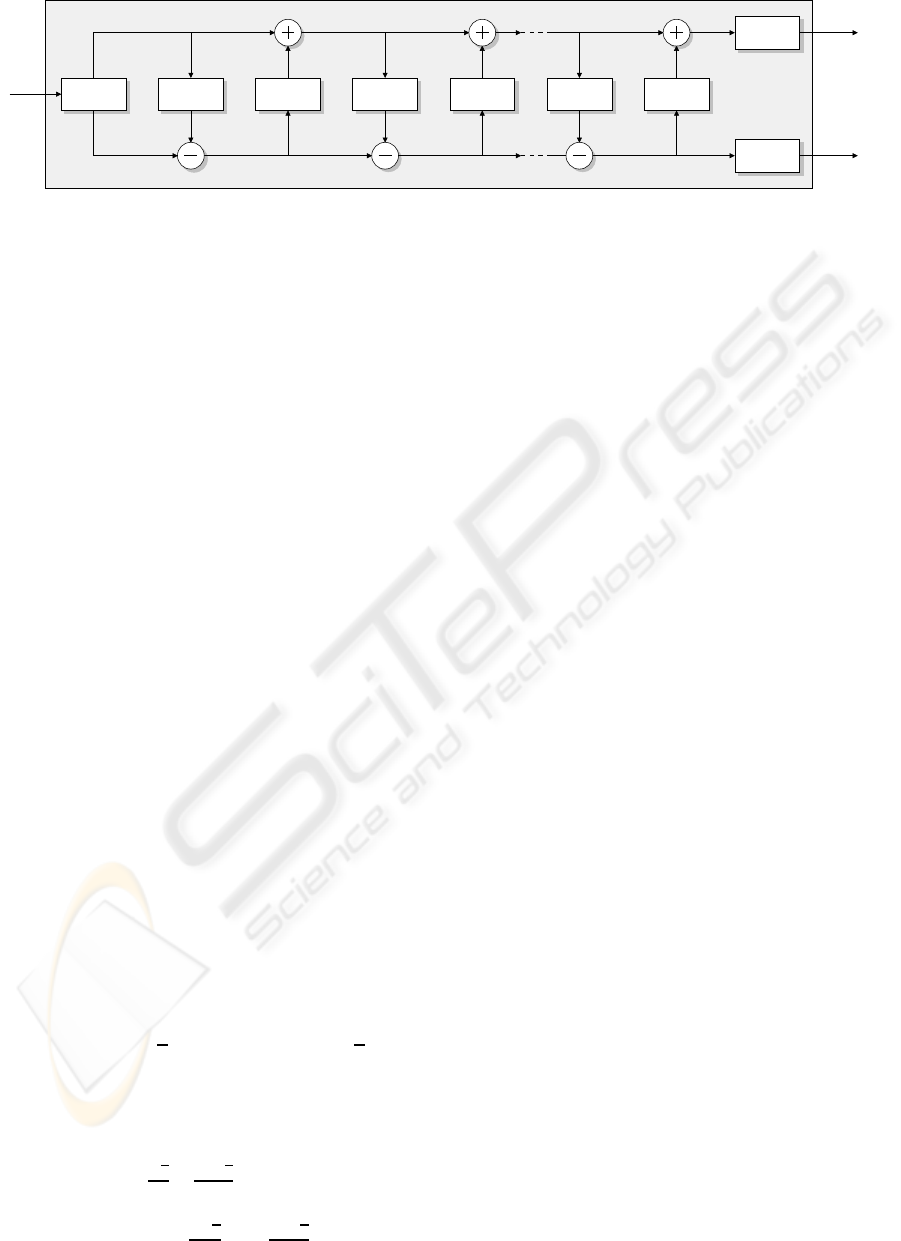
Figure 1 shows the arrangement of the lifting
scheme representation. The Laurent polynomials
b
i
(z) and a
i
(z) are expressed as predictor P
i
(z) and
updater U
i
(z). The signal S
j
is split into even and odd
parts. Prediction and update steps occur alternately.
The predictor P
i
(z) predicts the odd part from the even
part. The difference between the odd part and the pre-
dicted part is computed and used by the updater U
i
(z)
to update the even part. At the end, the low-pass and
the high-pass signals are normalized with a factor of
K and 1/K respectively.
By factoring the wavelet filters into lifting steps,
it is expected that the computation performed on
each stage (either it is a prediction or an update)
will be much less complex. As an example, the fa-
mous Daub-4 wavelet filter with the low-pass filter
response:
H(z) = h
0
+ h
1
z
−1
+ h
2
z
−2
+ h
3
z
−3
with h
0
=
1+
√
3
4
√
2
, h
1
=
3+
√
3
4
√
2
, h
2
=
3−
√
3
4
√
2
, and
h
3
=
1−
√
3
4
√
2
, can be factored into lifting steps:
P(z) =
"
√
3−1
√
2
0
0
√
3+1
√
2
#
1 −z
0 1
1 0
−
√
3
4
+
2−
√
3
4
z
−1
1
1
√
3
0 1
Since the finding of the greatest common di-
visors is not necessarily unique, the result of the
Laurent polynomials may also differ. The Daub-4
and the popular (5,3) and (9,7) wavelet filters can
SIGMAP 2008 - International Conference on Signal Processing and Multimedia Applications
70
S
j
S
j−1
D
j−1
S
j
odd
S
j
even
SPLIT
K
1/K
P
1
(z) U
1
(z) P
2
(z) U
2
(z) P
n
(z) U
n
(z)
Figure 1: Forward lifting steps.
be factored into lifting steps with maximum degree
of ±1 (Daubechies and Sweldens, 1998) whereas
Symlet-6 and Coiflet-2 (the lifting computations are
not detailed here due to page limitation) may have z
±5
factor on its Laurent polynomials.
3 PROPOSED ARCHITECTURE
The lifting-based forward DWT splits the signal into
even and odd parts at the first stage. The split signals
are processed by an alternating series of predictors
and updaters (on some wavelet filters an updater may
come before a predictor). On the final stage, the mul-
tiplication with the normalization factor takes place.
The inverse DWT performs exactly everything back-
wards. It starts with the multiplication with normal-
ization factor, continues with a series of updaters and
predictors, and finishes with the merging of the out-
puts. As the lifting scheme breaks a wavelet filter into
smaller predictions and updates, the resulting predic-
tor and updater can be limited to have a maximum
Laurent polynomial degree of one. Nevertheless, the
predictor or the updater of higher order wavelet filters
may have the higher factors as well. Without loss of
generality, we can formulate the predictor or the up-
dater polynomial as:
l(z) = c
1
z
−p
+ c
2
z
−q
with c
0
and c
1
as the polynomial constants and
|p−q|= 1. This implies that on each stage (either
as a predictor or an updater), two multiplications and
two additions are performed. As an example, the first
predict and update steps of Daub-4 can be written as:
s
′
d
=
1
√
3
0 1
s
d
=
s+ d ·
√
3
d
s
′
d
′
=
1 0
−
√
3
4
+
2−
√
3
4
z
−1
1
s
′
d
=
s
′
d + s
′
·
−
√
3
4
+ s
′
·
2−
√
3
4
z
−1
which perform one multiplication and one addition in
order to solve s
′
and two multiplications and two ad-
ditions to solve d
′
.
As a predictor and an updater perform a simi-
lar computation, the hardware architecture for both
functions is exactly the same. Taking this into ac-
count, we propose a new wavelet processor which
is based on NxM processing elements to cope with
N-dimensional wavelet computations and M lifting
steps. The N dimensions of our proposed wavelet pro-
cessor can be interpreted in various ways. For exam-
ple, the proposed wavelet processor with 2xM pro-
cessing elements can perform two concurrent DWTs
on a 2D image to compute the transformation on both
row and column data at the same time. In case of 1D
signal, it can be used to double the performance by
splitting the signal in half. Additionally, in case of
wavelet packets, the proposed NxM architecture can
perform the N different transformations in a simulta-
neous manner.
3.1 Architecture of the Processing
Element
The core behind our proposed architecture is the pro-
cessing element (PE), which performs the prediction
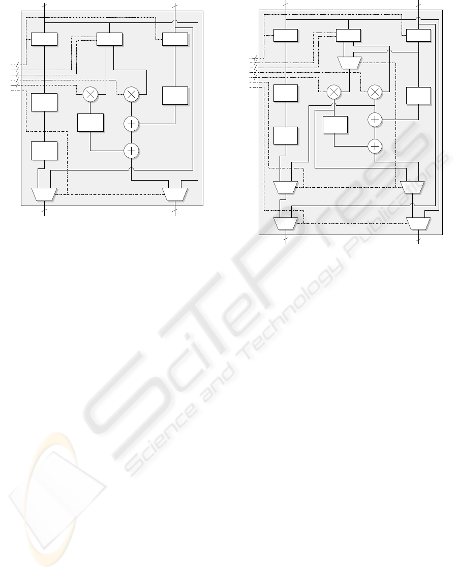
or the update. The PE is a pipeline-based architecture
in order to maximize the performance. Figure 2
depicts the proposed PE. The PE has two selectors S1
and S2 to choose the prediction or the update samples
that correspond to the factors p and q from the
Laurent polynomial. Two constants that represent the
filter coefficients are defined and configured by the
controller. By delaying the actual samples, selector
S3 controls the prediction or the update that requires
future samples. Selector S4 is a bypass selector.
Because lifting steps of higher order wavelet filters
may require distance prediction or update samples as
well, the maximum depth of the unit delay z
−m
, that
determines the maximum delay level, can be freely
chosen during the design.
The PE is divided into 3 blocks. The first block
CONFIGURABLE VLSI ARCHITECTURE OF A GENERAL PURPOSE LIFTING-BASED WAVELET PROCESSOR
71
C2
C1
S2
S1
S3
S4
N N
A B
N N
A’ B’
CONTROLLER
2M
M
M
N
N
1−level
FIFO
1−level
FIFO
FIFO
2−level
MUX MUX
1−level
FIFO
z
−m
z
−m
z
−m
Figure 2: Block diagram of the processing element.
organizes the input samples from both channels. The
second block performs the multiplication on the sam-
ples that are selected by S1 and S2 with the constants
C1 and C2. Two 1-level FIFOs on both input samples
are implemented to compensate the multiplier delay.
Taking into account that the lifting step constants are
not integers, a constant shifter is implemented inside
the multiplier as a replacement of an expensive di-
vider to perform the fixed-point multiplication. To
improve the accuracy, the result of the multiplication
is rounded. Because the normal rounding will con-
sume more logic, the rounding is performed in-place
by the adder. The multiplier outputs one bit after the
least significant bit as the fraction bit, and the adder
will use this fraction bit as the carry input. The last
block performs the additions of three values. One 2-
level FIFO is implemented to compensate the delay
which is introduced by two adders.
3.2 Normalization
As normalization can take place at the end of the
transformation in case of forward DWT or at the
beginning of the transformation in case of inverse
DWT, two special processing elements to handle
this function are required. Neglecting the predic-
tion/update process (addition between actual sample
and the predictor/updater values), normalization can
be performed on the PE. We extend the functional-
ity of the PEs that are located at the top and at the
bottom of the proposed wavelet processor instead of
implementing a dedicated normalization unit. Three
S5
C2
C1
S2
S1
S3
S4
N
N
A B
N N
A’ B’
CONTROLLER
2M
M
M
N
N
MUX MUX
1−level
FIFO
2−level
FIFO
MUX MUX
1−level
FIFO
MUX
1−level
FIFO
z
−m
z
−m
z
−m
Figure 3: Block diagram of the processing element which is
located at the top and at the bottom of a wavelet processor.
additional multiplexers are needed to add the normal-
ization factor unit into the PE. Figure 3 shows the
PE which is used at the top and at the bottom of the
proposed architecture. By enabling S5 and setting
S1 and S3 to zero, two inputs of the multiplexer be-
fore the multiplier correspond to the actual samples
s and d (with the normalization factors K = C1 and
1/K = C2. The multiplier on the right side performs
s
′
= Ks and goes to the left output. The multiplier on
the left side performs d
′
= d/K and goes to the right
output. Because the outputs of the PE will be cross-
linked to the inputs of the next PE, as detailed later,
the normalizer outputs are also cross-linked to cancel
this behaviour.
3.3 Controller
To cope with various lifting-based forward and in-
verse DWTs, we have separated the configuration de-
pendent parameters from the PE. Figures 2 and 3
showhowthe inputs of the selectors and the multiplier
constants are separately drawn on the left side of the
figures. In addition, the PE is designed to be simple.
Thus, no finite state machine is required to control the
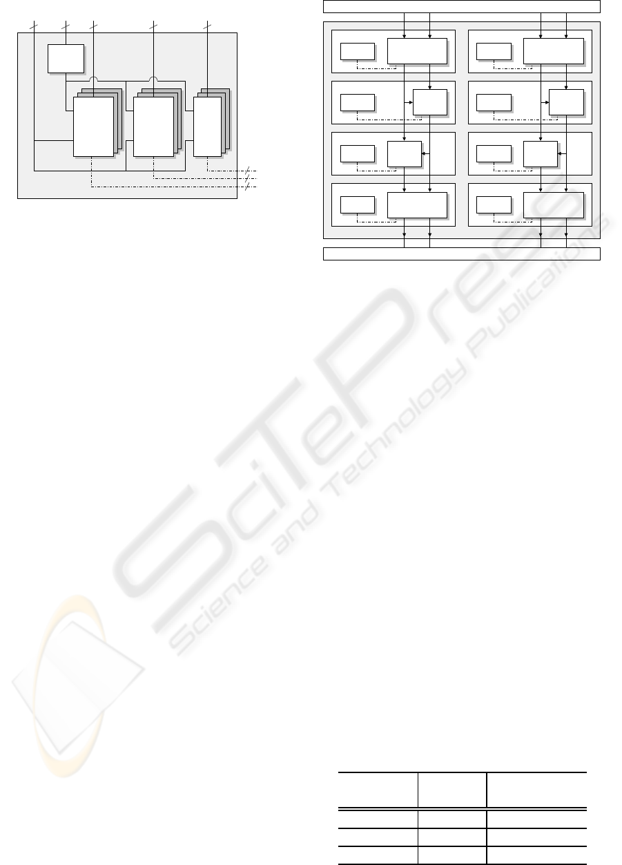
PE. To support different classes of wavelet filters, that
require different types of configurations, we have im-
plemented a multi-context configuration on each PE
as depicted in Figure 4. Each PE is assigned a row
index as a unique ID for the configuration. Multiplier
SIGMAP 2008 - International Conference on Signal Processing and Multimedia Applications
72
SELECTOR
CONTEXT
ID A B C
N N
N
N
CONFIGURATION
OUTPUT
COMP
WE
CONST
C1
CONST
C2
CTRL
Figure 4: Controller for the PE.
constants use the signal data paths to save the wiring
cost whereas the selector configuration requires ad-
ditional controller path. The context switch is im-
plemented as a memory module where the address is
controlled by the context selector and the write enable
signal is controlled by the output comparator. The ac-
tive configuration can easily be selected by using this
context-based controller to cope with various wavelet
filters. One benefit of having a multi-context con-
figuration is that the proposed wavelet processor can
be configured to perform the corresponding inverse
DWTs in a very simple manner. Additionally, wavelet
transformations that use longer wavelet filters can be
computed by splitting the lifting steps and the issues
regarding the boundary condition can be relaxed by
utilizing special wavelet filters on the signal bound-
aries which require less or no delayed/future samples
(e.g. Haar wavelet) instead of exploiting the periodic-
ity or the mirroring of the signal.
3.4 Processor with NxM PEs
Configuration
Taking into account that the predictions and the up-
dates occur alternately, the outputs of a PE will be
cross-linked to the inputs of the next PE. Due to the
nature of lifting steps, the prediction and the update
are computed in-place. It means that it is not neces-
sary to save the result or the temporary result into a
different memory. One simple implementation of the
proposed wavelet processor would consist of one PE.
By configuring each context with the corresponding
lifting step, the DWT/IDWT can be computed with
this simple implementation. Although it is possible to
use onle one PE, a typical wavelet processor will have
NxM PEs configuration to boost the performance and
to minimize memory access. Figure 5 depicts an ex-
ample of wavelet processor with 2x4 PEs which is ca-
pable to compute two concurrent DWTs/IDWTs.
CTRL CTRLPE PE
CTRL CTRLPE PE
CTRL PE PECTRL
CTRL PE CTRL PE
Figure 5: Wavelet processor with 2x4 PEs.
4 RESULTS AND
PERFORMANCES
The proposed wavelet processor is based on modular
and parametric approaches and is written in VHDL.
Wavelet processors with 2x8 PEs to process two con-
current forward/inverse DWTs and eight lifting steps
(including normalization), 8-level unit delays to sup-
port higher order wavelet filters, and 16 available
contexts to configure the transformations, are imple-
mented and synthesized. Note that wavelet filters that
require longer lifting steps can be split into several
large steps with a maximum number of eight. The de-
sign is synthesized using 0.18-µm technology. The es-
timated area and frequency of various data width im-
plementations are reported in Table 1. For the 16-bit
configuration, the proposed wavelet processor con-
sumes 1.76 mm
2
chip area and has a maximum op-
erating speed of 355 MHz. As a comparison, archi-
tecture from Andra with 16-bit data width in (Andra
et al., 2002) can only compute (5,3) and (9,7) filters
and required 2.8 mm
2
with 200 MHz operating fre-
quency.
We utilized integer multipliers and shifters to re-
Table 1: Estimated area and frequency of proposed wavelet
processor with 2x8 PEs.
Data Width
Est. Area Est. Frequency
(in mm
2
) (in MHz)
16-bit 1.764 354.61
20-bit 2.345 326.80
24-bit 2.989 306.75
CONFIGURABLE VLSI ARCHITECTURE OF A GENERAL PURPOSE LIFTING-BASED WAVELET PROCESSOR
73
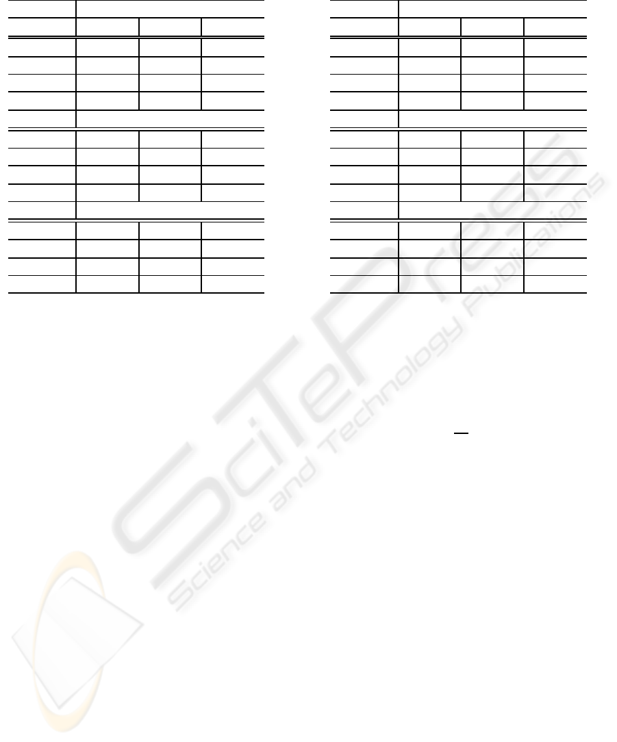
Table 3: SNR values of different data width implementa-
tions (in dB).
Daub-6
Source 16-bit 20-bit 24-bit
Sinusoid 56.983 80.774 98.382
Sawtooth 55.104 78.980 97.519
Step 57.985 86.321 101.949
Random 54.591 78.675 97.932
Symlet-6
Sinusoid 50.680 76.827 100.106
Sawtooth 49.552 74.849 99.615
Step 60.956 75.446 107.401
Random 48.951 74.318 99.817
Coiflet-2
Sinusoid 44.713 69.098 86.821
Sawtooth 43.101 66.870 85.231
Step 50.112 79.360 93.422
Random 44.169 67.260 87.490
duce the hardware cost in order to perform the fixed
point multiplications between the samples and the co-
efficients. As the consequence of this implementa-
tion, errors caused by the rounding of the wavelet co-
efficients and the multiplication results are expected.
In order to measure the accuracy of our proposed ar-
chitecture, we perform three different DWTs on some
predefined signals. Four different 8-bit full-swing
signals, which are used as references, are forward
and inverse transformed using Daub-6, Symlet-6, and
Coiflet-2 wavelet filters which do not have integer co-
efficients. The random signal has a uniform distribu-
tion. The lifting step coefficients of those wavelet fil-
ters are summarized in Table 2. These coefficients are
shortened to save space. ModelSim is used to com-
pare and verify the results. The SNR values of the
different data width implementations are reported in
Table 3 and the corresponding maximum errors are
reported in Table 4. Depending on the data widths,
SNR values vary between 43 dB and 107 dB, which
are sufficient for most applications. The 16-bit im-
plementation achieves lower SNR values due to the
fact that the lifting coefficients have a large dynamic
range that is between 0.001 and 64. The same reason
applies for Coiflet-2 wavelet filter. The improvement
of the SNR values can be achieved by increasing the
data width.
The proposed wavelet processor can accept input
data stream and perform the computation in every
clock cycle. The total latency on each PE is 4 clock
cycles. One clock cycle is used by the input regis-
ters, one by the multipliers, and two by the adders.
Table 4: Maximum error of different data width implemen-
tations.
Daub-6
Source 16-bit 20-bit 24-bit
Sinusoid 0.2500 0.0195 0.0029
Sawtooth 0.2500 0.0234 0.0024
Step 0.1875 0.0078 0.0019
Random 0.2500 0.0234 0.0024
Symlet-6
Sinusoid 0.8125 0.0430 0.0044
Sawtooth 0.7500 0.0430 0.0034
Step 0.5000 0.0352 0.0024
Random 0.8125 0.0547 0.0049
Coiflet-2
Sinusoid 1.3125 0.0703 0.0117
Sawtooth 1.2500 0.0664 0.0102
Step 1.3750 0.0352 0.0088
Random 1.1250 0.0742 0.0093
Additional sample latency (one clock cycle per future
sample) will add-up to the total latency on the PEs,
which require this feature. The PE that is configured
as a normalizer has latency of 2 clock cycles only.
For the NxM wavelet processor, the total time
needed to compute L-stage forward/inverse DWT is:
T = T
d
L+
2S
N
(1−0.5
L
)
where S is the signal length and T
d
= M ×T
PE
is the
circuit delay with T
PE
as the PE latency delay.
5 CONCLUSIONS
We have detailed a novel architecture that is able to
compute various wavelet transformations and their in-
verses, based on their lifting scheme representations.
The proposed wavelet processor is based on NxM PEs
and can accept continuous data streams. It can also be
configured easily to support higher order lifting poly-
nomials, as the result of the factorization of higher
order wavelet filters. To cope with different wavelet
filters, the developed wavelet processor includes a
multi-context configuration so that users can easily
switch between transformations (including their in-
verses). The proposed wavelet processor is config-
urable to adapt the application demand that requires
different accuracy. Additionally, the proposed archi-
tecture takes into account the normalization step that
occurs at the end of the forward DWT or at the begin-
ning of the inverse DWT. The proposed wavelet pro-
SIGMAP 2008 - International Conference on Signal Processing and Multimedia Applications
74
Table 2: Lifting coefficients of Daub-6, Symlet-6, and Coiflet-2 wavelet filters.
Type Daub-6 Symlet-6 Coiflet-2
Updater 2.425 z
0
-0.227 z
0
-2.530 z
0
Predictor 0.079 z
−1
-0.352 z
0
-1.267 z
−1
0.216 z
0
-0.240 z
−1
0.342 z
0
Updater -2.895 z
1
0.561 z
2
0.505 z
1
-4.255 z
2
3.163 z
1
15.268 z
2
Predictor -0.020 z
−2
0.045 z
−3
0.233 z
−2
0.006 z
−3
-0.065 z
−2
Updater -18.389 z
3
6.624 z
4
-63.951 z
3
13.591 z
4
Predictor 0.144 z
−5
-0.057 z
−4
0.001 z
−5
0.002 z
−4
Updater -5.512 z
5
-3.793 z
5
Normalizer 0.432 2.315 -0.599 -1.671 0.108 9.288
cessor is capable to receive continuous data streams
and compute the transformation in every clock cy-
cle. Using 0.18-µm technology, the estimated area of
the proposed wavelet processor with 16-bit configura-
tion is 1.8 mm
2
and the estimated operating speed is
355 MHz.
REFERENCES
Agbinya, J. (1996). Discrete wavelet transform techniques
in speech processing. In Proceeding of the IEEE TEN-
CON. Digital Signal Processing Applications, TEN-
CON ’96, volume 2, pages 514–519.
Andra, K., Chakrabarti, C., and Acharya, T. (2002). A
VLSI architecture for lifting-based forward and in-
verse wavelet transform. IEEE Trans. Signal Process-
ing, 50(4):966–977.
Barua, S., Carletta, J., Kotteri, K., and Bell, A. (2004).
An Efficient Architecture for Lifting-based Two-
Dimensional Discrete Wavelet Transforms. In Pro-
ceedings of the GLSVLSI’04.
Bultheel, A. (2003). Wavelets with applications in signal
and image processing. -.
Calderbank, R., Daubechies, I., Sweldens, W., and Yeo, B.-
L. (1997). Lossless image compression using integer
to integer wavelet transforms. Proceedings of the In-
ternational Conference on Image Processing, 1:596–
599.
Carnero, B. and Drygajlo, A. (1999). Perceptual speech
coding and enhancement using frame-synchronized
fast wavelet packet transform algorithms. IEEE Trans.
Signal Processing, 47:1622–1634.
Christopoulos, C., Skodras, A., and Ebrahimi, T.
(2000). The JPEG2000 still image coding sys-
tem: an overview. IEEE Trans. Consumer Electron.,
46(4):1103–1127.
Daubechies, I. (1990). The wavelet transform, time-
frequency localization and signal analysis. IEEE
Transactions on Information Theory, 36:961–1005.
Daubechies, I. and Sweldens, W. (1998). Factoring Wavelet
Transforms into Lifting Steps. J. Fourier Anal. Appl.,
4(3):245–267.
Dillen, G., Georis, B., Legat, J., and Cantineau, O. (2003).
Combined line-based architecture for the 5-3 and 9-7
wavelet transform of JPEG2000. IEEE Trans. Circuits
Syst. Video Technol., 13(9):944–950.
Grgic, S., Kers, K., and Grgic, M. (1999). Image com-
pression using wavelets. In Kers, K., editor, Proc.
IEEE International Symposium on Industrial Elec-
tronics ISIE ’99, volume 1.
Kaisheng, Y. and Zhigang, C. (1998). A wavelet fil-
ter optimization algorithm for speech recognition.
In Intl. Conference on Communication Technology
Proc., ICCT ’98, volume vol.2, page 5pp.vol.2.
Mallat, S., editor (1998). A Wavelet Tour of Signal Process-
ing. Academic Press, Incorporated.
Martina, M., Masera, G., Piccinini, G., and Zamboni, M.
(2000). A VLSI architecture for IWT (Integer wavelet
Transform). In Masera, G., editor, Proceeding of the
43rd IEEE Midwest Symposium on Circuits and Sys-
tems, volume 3.
Meyer, Y. (1992). Wavelets and Operators. Press Syndicate
of the University of Cambridge.
Seo, Y.-H. and Kim, D.-W. (2006). A New VLSI Architec-
ture of Lifting-Based DWT. Lecture Notes in Com-
puter Science, 3985/2006:146–151.
Sweldens, W. (1995). The Lifting Scheme: A New Philos-
ophy in Biorthogonal Wavelet Constructions. Wavelet
Applications in Signal and Image Processing, 3:68–
79.
Usevitch, B. (2001). A tutorial on modern lossy wavelet
image compression: foundations of JPEG2000. IEEE
Signal Processing Mag., 18(5):22–35.
CONFIGURABLE VLSI ARCHITECTURE OF A GENERAL PURPOSE LIFTING-BASED WAVELET PROCESSOR
75
