
MOTION CAPTURE FOR 3D DATABASES
Overview of Methods for Motion Capture in 3D Databases
Dalibor Lupínek and Martin Drahanský
Brno University of Technology, Faculty of Information Technology, Božetěchova 2, Brno, Czech Republic
Keywords: Motion capture, motion, animation, kinematics.
Abstract: Motion capture is a modern method which is commonly used in animation and augmented reality. There
exists a large variety of functional systems that are based on different principles. The main concept of this
paper is to provide a preview for basic description of potential motion capture systems that are widely used
or represent a promising future. In addition, this paper presents an overview of a new system, which is now
in development.
1 INTRODUCTION
Motion Capture is an attractive method that makes
computer animation easier and more accurate. It
provides a realistic model of actor’s motion. It al-
lows the actor to work together with the director on
creating desired motion that is too complex to be
described in sufficient accuracy for it to be made by
classic hand animation techniques. As almost every-
thing, even motion capture has its weaknesses. In
order to capture the desired motion in required de-
tail, motion capture methods create large quantity of
unstructured data, with which is hard to manipulate.
Another weakness of motion capture is the process
of acquiring data which is commonly quite compli-
cated. While the development in methods for data
processing and for its utilization was in the past
years very fast, motion capture methods evolve in
comparison to them quite slowly. In order to acquire
needed data it is required to use special tracking
technology based on mechanical or magnetic sensors
or specially designed video cameras that trace atten-
tively placed and illuminated special markers. Al-
though these systems became over time sufficiently
accurate and reliable, they remain rather expensive
and relatively complex. This is the reason among
others that high quality motion capture can be today
carried out only by specialized studios.
Motion capture became an essential part of ani-
mation and augmented reality systems. Its objective
is to provide for the animator fast, accurate and if
possible low cost models of real motion. In the last
years a lot of effort is put in systems which use a
simple useable method for acquiring motion capture
data that preserver the system robustness. The data
processing should be fast and with minimal need for
human interaction, ideally none. Despite the exis-
tence of a number of high quality motion capture
systems based on various principles, a system that
would satisfy all these requirements does not exist
(yet). Therefore, it is essential when choosing a spe-
cific system to consider what is actually required
from this system. What kind of data should it pro-
duce, how accurate should be the capture of the de-
sired motion, degree of freedom of individual seg-
ments that will be captured, space requirements of
the motion, what kind of environment is available
and of course how much funds are available for the
whole system. Generally, like in a wide range of
other fields, it applies that systems that produce bet-
ter results tend to more expensive, then those that
produce worse results.
A lot of expectations are put in simple optical
marker-less systems that use a small amount of cam-
eras (Bregler and Malik, 1997). These systems do
not need any kind of special environment or special
suits, but their robustness is not yet very high.
Another type of a promising motion capture system
is the kind that uses imperceptible photo sensing
markers (Raskar, 2007). But this principle requires
that on the actor are mounted special tags, however
they are quite small and do not restrain the actor in
motion. These tags in addition need a power supply
and this system uses a special and expensive camera.
Inertial systems (Moven, 2007) could satisfy most of
the requirements. Their main disadvantage is the
99
Lupínek D. and Drahanský M. (2008).
MOTION CAPTURE FOR 3D DATABASES - Overview of Methods for Motion Capture in 3D Databases.
In Proceedings of the International Conference on Signal Processing and Multimedia Applications, pages 99-104
DOI: 10.5220/0001931900990104
Copyright
c
SciTePress
need of a special suit with inertial sensors. These
sensors are getting over the time smaller and small-
er, so they do not restrain the actor in his motion.
2 OPTICAL MOTION CAPTURE
Optical systems for motion capture are based on
computer imaging and ideally with the use of mini-
mum cameras should be able to record the motion of
any figure in any environment, similarly to how it is
done by humans. Current systems are however quite
far from doing so. Usually the use of markers, which
are placed on human joints, is necessary. This ap-
proach dramatically simplifies and makes the cap-
ture of the motion more precise. But the use of
markers has also some drawbacks. One of them is
the identification of markers and their correct asso-
ciation to the corresponding part of the figure. This
identification is basically performed in the phase of
motion recording or subsequently in the phase of
data processing. Generally the optical motion cap-
ture systems can be divided according to the types of
markers which label the body parts or joints of the
figure.
2.1 Passive Markers
Passive optical systems use markers with reflexive
surface, so they are able to reflect as much light as
possible back to the camera. The sensitivity of the
cameras is often altered, so only bright tags are re-
corder and the rest is ignored. The center point of the
marker is determined from a 2D projection which is
recorded. For sub-pixel accuracy the gray scale val-
ue of the pixel can be used. 3D object localization
can be acquired using two calibrated cameras fixed
on this object. For calibration of the cameras there is
used a set of markers with a known position. These
systems are usually made of 6 – 24 cameras, but
systems with 200 cameras can also be found. The
cost of a basic 8 camera system including software
reaches 100 000 USD.
Great advantage of passive markers is that the
actor does not have to wear cables or some electron-
ic device. Passive markers are fixed directly to the
figures clothing or even to his skin. This system is
able to record a large amount of markers with the
frequency up to 2 000 pictures per second or more,
in dependence on the quality of the used cameras.
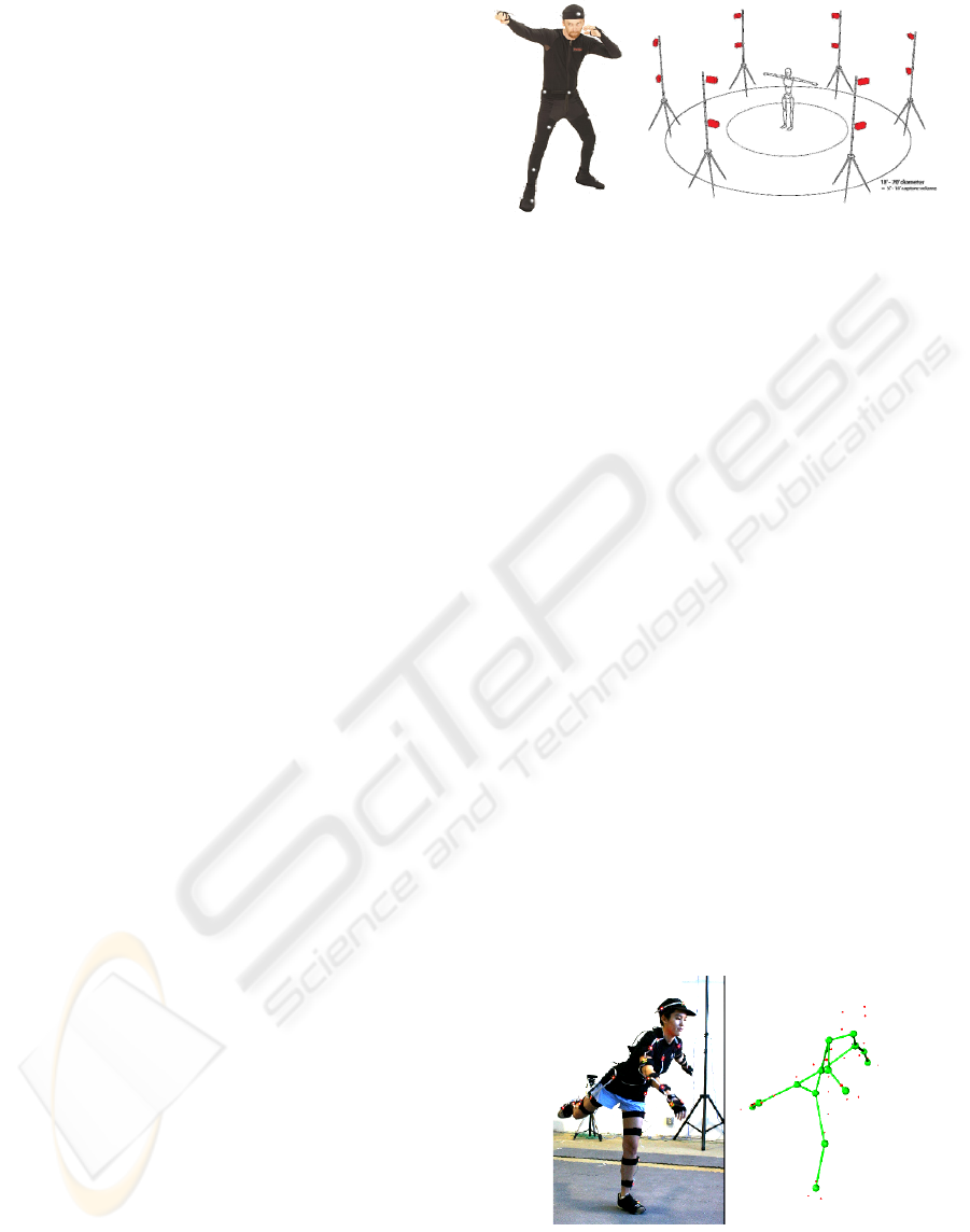
Figure 1: A person wearing a suit with passive reflective
markers and the camera placement for motion capture
system OptiTrack (OptiTrack, 2008).
2.2 Active Markers
Active optical systems use consecutive lighting of
individual LED for marker triangulation. The light-
ing of marker is done in high frequency and only
one LED is lighted at a time. Because the markers
generate their own light instead of reflecting it, it is
possible to capture motion from a greater distance
and in larger spaces. This method is used when fast
processing is required, e.g. in real time systems. If
the requirement for speed is more important than
quality requirements, the system lights all the LEDs
at one time or the LEDs are switched on permanent-
ly.
Active marker systems can be enhanced by re-
cording several markers at one time and modulation
their amplitude or pulse width. This provides addi-
tional information to the system for identifying the
marker, which speeds up the data processing. LEDs
with a microcontroller with radio synchronization
enable to carry out the motion capture outside in
direct sunlight. The use of modulated markers re-
duces the need of human interaction in the phase of
data processing, which leads to fund saving. Visua-
leyez VZ4000 (PTI, 2008) from PhoeniX Technolo-
gies is one of these systems.
Figure 2: Actor dressed in a suit with active reflective
markers and a processed picture of the final kinematical
model (Kirk, 2004).
SIGMAP 2008 - International Conference on Signal Processing and Multimedia Applications
100
2.3 Semi-Passive Imperceptible
Markers
Systems represented by Prakash (Raskar, 2007) use
relatively cheap multi-LED high-speed projectors.
Special built-in multi-LED IR projectors optically
code the area. Instead of reflective or active LED
markers the system uses light-sensitive tags to de-
code optical signals. After the installation of the tags
with photo sensors to the scene points, the system is
able to calculate not only the location, but also
orientation, incident luminescence and reflection.
These trace tags are undetectable by the eye and
can be fixed on the clothing or some object. They
are even functional in outside environment. The
scene can have unlimited amount of tags since each
one is uniquely identifiable. With this all the prob-
lems with the identification of the tags and their
eventual mismatch disappear. This system has lower
demand for data processing since it does not require
high speed cameras. Thanks to the tag ability to pro-
vide incident luminescence of the scene this method
is suitable for real time projection of virtual scenes.
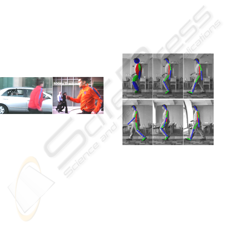
Figure 3: Prakash system, the tags are under the clothing
and are activated by a multi-LED camera in the car
(Raskar, 2008).
2.4 Markerless
This method is the result of research done by C.
Bregler and J. Malik at the University of California
(Bregler and Malik, 1997) and (Chen, Jenkins, Ma-
taric, 2003 & Corazza, Mundermann, Andriacchi,
2006). This method is more or less straight forward
from the user’s point of view. The user has to mark
each segment of the limb on the initial picture. If
there are available video streams from several syn-
chronized cameras, than segments in initial frames
of all streams have to be labeled. The computer pro-
gram does the rest, it seeks the position of segments
in all consecutive pictures. The goal of this approach
is to determine the movement in real environment
and usual clothing.
Authors of this method introduced a mathemati-
cal technique which is the result of exponential maps
and rotation movement integrated into a differential
scheme for the moment prediction. A great advan-
tage of this approach is that only linear equations are
needed for the actualization of movement parame-
ters in the subsequent pictures.
This method has been applied to several record-
ings of human walk and the exact recognition of the
complete body movement was reached. This move-
ment was then recreated in the animation process.
There exist many methods of visual surveillance
techniques. Most of them are based on edge detec-
tions, are detection or some kind of differential ap-
proach.
Edge detection requires clean data with high con-
trast edges of individual objects. This is quite diffi-
cult when trying to record movement of humans. In
this case the segments which are to be recognized
are often very noisy. Area detection enables the
tracking of objects of different texture. The differen-
tial approaches map local changes of intensity and
the change of various parameters.
Figure 4: Example of identified movement structure. The
first picture shows auxiliary maps created by initialization.
Color lines in the following pictures describe the axis of
color areas (Bregler and Malik, 1997).
3 NON-OPTICAL MOTION
CAPTURE METHODS
There exist quite a large amount of non-optical me-
thods used for motion capture. Unfortunately all of
them require special suits with sensors tracing the
movement by recording the change of position in
time or by recording absolute positions. The main
disadvantages of these systems are the need to pow-
er individual sensors and to secure data transmission
from them. On the other hand the data processing is
quite fast, because the tags do not need to be identi-
MOTION CAPTURE FOR 3D DATABASES - Overview of Methods for Motion Capture in 3D Databases
101
fied. The accuracy is also high. Due to the fact, that
sensors are getting smaller and have smaller power
consumption, the utility of these systems is rising
rapidly without the rise of costs.
3.1 Inertial Systems
Inertial technology (Luinge, 2002) of motion picture
is based on miniature inertial sensors and biome-
chanical models. It is a relatively cheap and easy to
use method for movement capture of the body. The
information about movement is wirelessly transmit-
ted to a computer, where the information is dis-
played or stored. No cameras or markers for the rela-
tive movement tracking are necessary. Inertial mo-
tion capture systems capture the motion with six
degrees of freedom in real time. Advantages of these
systems are easy transfer and the ability to record in
wide areas. These systems are able to exactly cap-
ture rotation movement with the accuracy higher
than one degree. The price of these suits reaches
50 000 USD.
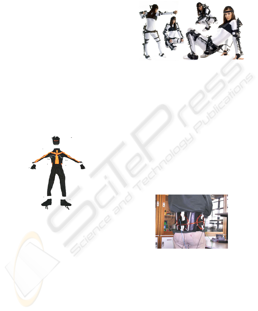
Figure 5: The suit for inertial motion capture created by
MOVEN (Inition, 2008).
3.2 Mechanical Systems
Mechanical motion capture systems record the angle
of rotation of the figures joints directly. These sys-
tems are often named exo-skeleton Motion capture.
A person is dressed in a structure resembling a ske-
leton. During every movement of the person the me-
chanical parts of the exo-skeleton also move. These
parts measure the relative movement. Mechanical
systems are real-time, cheap, without any distortion
and some are even wireless. They also enable to
capture movement in environment of any size.
Usually the exo-skeleton is a solid structure made up
of straight iron or plastic bars with joints that are
connected to a potentiometer. The price of these
systems may vary from 25 000 to 75 000 USD. Un-
fortunately an external system for the determination
of the absolute position must be connected to it.
Figure 6: Mechanical motion capture system GYPSY6
made by Inition (Inition, 2008).
3.3 Magnetic Systems
Magnetic motion capture systems (Roetenberg,
2006) determine the position and orientation from a
relative magnetic inductive current of three ortho-
gonal coils situated on the receptor and the transmit-
ter. The markers are not influenced by non-metal
objects in the environment, but can be interfered by
magnetic and electrical fields created by metal ob-
jects, such as iron reinforcement in concrete, cables,
monitors, lights, etc. The cables connected to sen-
sors can limit the movement. The area in which this
system can be used is considerably smaller com-
pared to optical systems, but because the output of
each sensor describes six degrees of freedom the
number of needed sensors is smaller.
Figure 7: Prototype of a magnetic tracking system (Roe-
tenberg, 2008).
4 APPLICATED APPROACH
Part of this paper is also a presentation of a system
that is being designed at our faculty at the moment.
This system should present a cheap and easy to use
motion capture method that works even with streams
made by common video cameras. It has origins in
the classic concept of optical motion capture system
with passive markers. It seeks to find a simple me-
SIGMAP 2008 - International Conference on Signal Processing and Multimedia Applications
102
thod that would identify the markers, or at least
make the identification process easier.
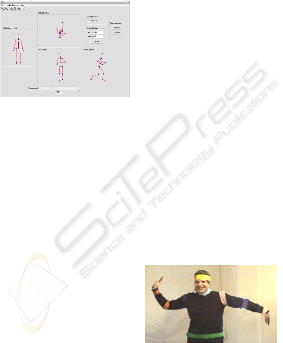
Figure 8: Prototype of a control application for the system.
So far quite promising seems to be color distinc-
tion of the individual markers. However with out of
post processing of the captured video stream, which
would be ideal, this approach can identify only a
small amount of markers.
As in different methods, a large problem is in-
homogeneous illumination, which occurs in most
common environments. Creating a homogeneously
illuminated environment that would prevent the cre-
ation of shadows is possible, although it brings with
it not just higher cost, but also limitation of the space
in which the captured movement can take place in.
One of the commonly used methods to reduce the
effect of inhomogeneous illumination is to convert
the frames from the captured stream to some kind of
more suitable color model as is YUV. In this case
during the identification of the markers the bright-
ness component is ignored. However with this
change comes also a significant reduction of useable
colors for the markers. A basic human body model
consists of about 30 markers and with the described
approach it is possible to distinguish only about 10
markers in dependency on the quality of the envi-
ronment in which is the capture carried out.
A possible way how to overcome this problem is
the division of the segments that will be captured in
to groups. Each group will consist of those segments
that have the lowest probability of mutual substitu-
tion in comparison to the other segments. When ap-
plied to the mentioned basic human model these
groups would consist of three segments, which
would be represented with a marker of a same color.
With the assumption that the size of the segments
does not vary in time, which is a case of for instance
segments that represent human bones, can the seg-
ments be distinguished one another by comparing
their length to a reference model. In some cases this
could happen to be insufficient and there will be a
need of an auxiliary identification method. In this
case the absolute position of the candidate segments
will be compared with the one in the previous frame.
The identification will be then made on base of the
size of the difference with the presumption that
small differences are more probable then the large
ones. Another approach that could make the process
more accurate is to decide on the base of motion
restriction, if a specific motion is even possible to be
performed. This would unfortunately require the
system to have the knowledge of motion restrictions
of all segments. Current version of this system does
not presume this kind of knowledge to be known.
Along with the development of this system is be-
ing experimented with different kind of nontradi-
tional markers. At this moment best results seem to
have different color fabric stripes. These stripes un-
like common markers, which are basically point like,
are around the whole joint. This largely increases the
visibility of the markers and reduces the number of
needed cameras to cover the desired motion. In the
process of extraction of the position of individual
markers is located an area in the frame with corres-
ponding color. Then the center of this area is deter-
mined, which represents the position of the marker
for other phases of data processing. Another advan-
tage of this approach is that if the cameras are prop-
erly placed then it is possible to compute the center
of the joint. One of the disadvantages is the defor-
mation of the textile stripes during motion, which
results in the change of its size and could lead to
inaccuracies. Solution to this problem could be the
use of a simple tight outfit that would have the
stripes mounted solidly. Even though this would
make this system more complex and this suit would
have a higher cost then textile stripes, it would still
be considerably cheaper to other costs.
Figure 9: Example of a prototype suit for the system.
MOTION CAPTURE FOR 3D DATABASES - Overview of Methods for Motion Capture in 3D Databases
103

5 CONCLUSIONS
Despite of motion capture being a quit new applica-
tion of computer science proceedings it is widely
spread and is experiencing a large progression. It is
the essence of modern animation and augmented
reality systems could with out it hardly exist. To this
date a large variety of systems based on all kind of
technologies tend to show satisfying results. Unfor-
tunately a widely useable and affordable system was
not yet presented. That is why it is necessary to care-
fully analyze the requirements of the application that
will use the output data in order to determine the
correct motion capture system.
Mechanical systems were in the past the best and
almost only choice. They are able to quickly provide
accurate results but the need of an exo-skeleton
makes them today less popular and today they are
being pushed out be inertial systems and optical sys-
tems. Inertial systems seem to present one of the
best choices for whole body motion capture. They
are widely usable, almost without limitations and
relatively low cost. Optical systems tend to have a
brighter future, as it seems today that they present a
base which could one day become an ideal motion
capture system.
The applied approach that is described in this pa-
per could present another alternative optical motion
capture system that would present a simply useable
cheap system with an unsophisticated implementa-
tion. To this day however there is a lot to be done on
it. In the near future it is planed to implement a
widely functional marker identification technique
and finish experiments with alternative markers. The
next step will be creation of a user friendly applica-
tion that would control the system and make possi-
ble for user to make custom improvements to the
final motion model. At the end of the system devel-
opment will be performed test, which will determine
the required number of cameras to capture variously
sophisticated movements. In this phase the practical
usability of this system will be evaluated.
ACKNOWLEDGEMENTS
This research has been done under the support of the
grant “Security-Oriented Research in Information
Technology”, MSM0021630528 (CZ) and the sup-
port of the company E-COM s.r.o.
REFERENCES
Bregler C., Malik J., 1997 Video Motion Capture, Com-
puter Science Division, University of California.
Raskar R.P., 2007, Lighting Aware Motion Capture using
Photosensing Markers and Multiplex Illuminators,
MERL, Cambridge.
Moven, 25.12.2007, http://www.moven.com/en/
home_moven.php
OptiTrack, Optical Motion Capture Polutions, 18.3.2008,
http://www.naturalpoint.com/optitrack/
PTI Inc., 2008, VisualEyez VZ 4000.
Kirk A., O’Brien J. F., Forsyth D. A., 2004, Skeletal Pa-
rameter Estimation from Optical Motion Capture Da-
ta, University of California.
Inition, Gypsy6, http://www.inition.co.uk/
Roetenberg D., 2006, Inertial and Magnetic Sensing of
Human Motion, Universiteit Twente.
Chu C.-W., Jenkins, O.C., Mataric, M., 2003, Markerless
Kinematic Model and Motion Capture from Volume
Sequences, Computer Science Division, University of
California.
Corazza S., Mundermann L., Andriacchi T., 2006, Mar-
kerless Motion Capture Methods for the Estimation of
Human Body Kinematics, Mechanical Engineering
Dept., Stanford University, Stanford CA.
Luinge H.J., 2002, Inercial Sensing of Human Movement,
Twente University Press, Netherland.
SIGMAP 2008 - International Conference on Signal Processing and Multimedia Applications
104
