
FPGA-TARGETED HARDWARE IMPLEMENTATIONS OF K2
Shinsaku Kiyomoto, Toshiaki Tanaka
KDDI R & D Laboratories Inc., 2-1-15 Ohara Fujimino-shi Saitama 356-8502, Japan
Kouichi Sakurai
Kyushu University, 744 Motooka Nishi-ku Fukuoka 819-0395, Japan
Keywords:
Stream Cipher, K2, Pseudorandom Generator, Hardware Implementation, FPGA.
Abstract:
K2 is a new type of word oriented stream cipher that has dynamic feedback control. Existing research has
shown that K2 v2.0 is a high performance stream cipher in software implementations and can be used in several
applications. However, no evaluation results for its performance in hardware implementations have been
published. In this paper, we presented two hardware implementations of K2 v2.0: a high speed implementation
and a compact implementation. We then show the evaluation results on FPGA implementation simulations.
The implementations of K2 demonstrated high efficiency compared with other stream ciphers, with K2 being
4-10 times higher than AES implementations. We think that the FPGA implementation of K2 is suitable for
applications using high speed encryption/decryption.
1 INTRODUCTION
Stream ciphers are used extensively to provide a re-
liable, efficient method for secure communications.
A basic stream cipher uses several independent linear
feedback shift registers (LFSRs) together with non-
linear functions in order to produce a keystream. The
keystream is then XORed with plaintext to produce
a ciphertext. Recently, word-oriented stream ciphers
have been developed in order to improve the perfor-
mance of software implementations. In the NESSIE
project
1
, many word-oriented stream ciphers were
proposed, such as SNOW(Ekdahl and Johansson,
2000) and SOBER(Rose and Hawkes, 1999), and
demonstrated good performance in software.
The need for secure data exchange becomes im-
portant not only for high-end PCs but also low-end
customer products. Most of low-end devices require
an additional hardware implementations for encryp-
tion/decryption of transaction data. Efficient hard-
ware implementations of stream ciphers are impor-
tant in both high-performanceand low-power applica-
1
New European Schemes for Signatures, Integrity,
and Encryption (NESSIE),
https://www.cosic.esat.
kuleuven.be/nessie/
tions. On the eSTREAM project
2
, many evaluation
results of hardware performances of stream ciphers
have been reported.
K2 (Kiyomoto et al., 2007b) (Kiyomoto et al.,
2007a) is a new word-oriented stream cipher us-
ing dynamic feedback control as irregular clocking.
The stream cipher has a dynamic feedback control
mechanism for the byte-level feedback function of
FSRs and realizes fast encryption/decryption for soft-
ware implementations. Several cryptographic algo-
rithms have been considered hardware implementa-
tions (Rodr´ıguez-Henr´ıquez et al., 2007). Existing re-
search has shown that K2 v2.0 is a secure and high-
performance stream cipher in software implementa-
tions and can be used in several applications. How-
ever, no evaluation results for the performance of
hardware implementations have been published. In
this paper, we presented two hardware implementa-
tions of K2 v2.0: a high speed implementation and
a compact implementation. We then show their eval-
uation results on FPGA implementations. The eval-
uation results suggested that the cipher is faster than
existing ciphers and attains a reasonable level of ef-
2
ECRYPT eSTREAM
http://www.ecrypt.eu.org/
stream/
270
Kiyomoto S., Tanaka T. and Sakurai K. (2008).
FPGA-TARGETED HARDWARE IMPLEMENTATIONS OF K2.
In Proceedings of the International Conference on Security and Cryptography, pages 270-277
DOI: 10.5220/0001917002700277
Copyright
c
SciTePress
ficiency. We think that the FPGA implementation of
K2 is suitable for applications using high speed en-
cryption/decryption.
2 STREAM CIPHER K2 V2.0
In this section, we describe the stream cipher algo-
rithm K2 v2.0 (Kiyomoto et al., 2007a), which has a
dynamic feedback control mechanism.
2.1 Linear Feedback Shift Registers
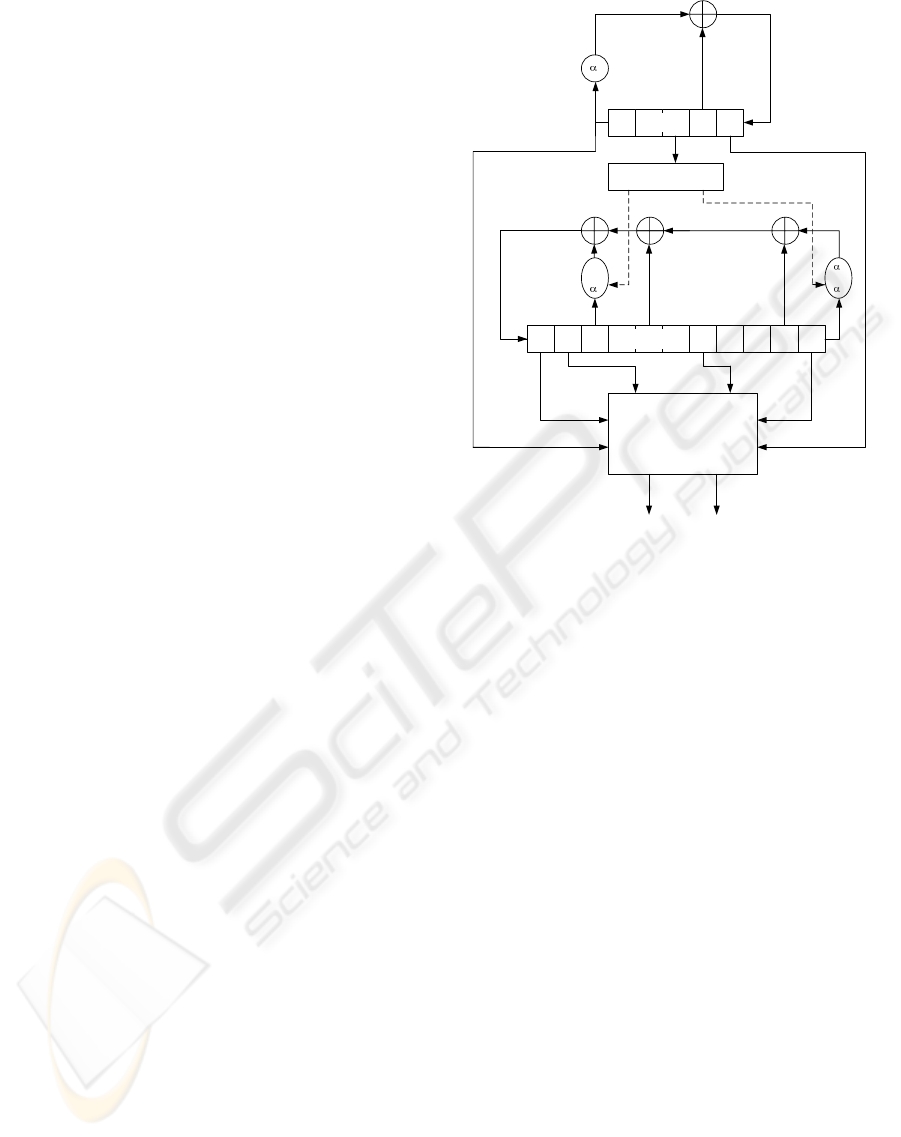
The K2 v2.0 stream cipher consists of two feedback
shift registers (FSRs), FSR-A and FSR-B, a non-linear
function with four internal registers R1, R2, L1, and
L2, and a dynamic feedback controller as shown in
Fig. 1. FSR-B is a dynamic feedback shift register.
The size of each register is 32 bits. FSR-A has five
registers, and FSR-B has eleven registers. Let β be
the roots of the primitive polynomial;
x
8
+ x
7
+ x
6
+ x+ 1 ∈ GF(2)[x]
A byte string y denotes (y
7
,y
6
,...,y
1
,y
0
), where y
7
is
the most significant bit and y
0
is the least significant
bit. y is represented by
y = y
7
β
7
+ y
6
β
6
+ ... + y
1
β+ y
0
In the same way, let γ, δ, ζ be the roots of the primitive
polynomials,
x
8
+ x
5
+ x
3
+ x
2
+ 1 ∈ GF(2)[x]
x
8
+ x
6
+ x
3
+ x
2
+ 1 ∈ GF(2)[x]
x
8
+ x
6
+ x
5
+ x
2
+ 1 ∈ GF(2)[x]
respectively.
Let α
0
be the root of the irreducible polynomial of
degree four
x
4
+ β
24
x
3
+ β
3
x
2
+ β
12
x+ β
71
∈ GF(2
8
)[x]
A 32-bit string Y denotes (Y
3
,Y
2
,Y
1
,Y
0
), where Y
i
is
a byte string and Y
3
is the most significant byte. Y is
represented by
Y = Y
3
α
3
0
+Y
2
α
2
0
+Y
1
α
0
+Y
0
Let α
1
, α
2
, α
3
be the roots of the irreducible polyno-
mials of degree four
x
4
+ γ
230
x
3
+ γ
156
x
2
+ γ
93
x+ γ
29
∈ GF(2
8
)[x]
Dynamic Feedback
Controller
B
t
FSR-B
0
A
t
FSR-A
Non-Linear Function
Keystream (64bits)
1
or
2
B
t+10
A
t+4
1
or
3
z
H
t
z
L
t
Figure 1: K2 v2.0 Stream Cipher.
x
4
+ δ
34
x
3
+ δ
16
x
2
+ δ
199
x+ δ
248
∈ GF(2
8
)[x]
x
4
+ ζ
157
x
3
+ ζ
253
x
2
+ ζ
56
x+ ζ
16
∈ GF(2
8
)[x]
respectively.
The feedback polynomials f
A
(x), and f
B
(x) of
FSR-A and FSR-B, respectively, are as follows;
f
A
(x) = α
0
x
5
+ x
2
+ 1
f
B
(x) = (α
cl1
t
1
+α
1−cl1
t
2
−1)x
11
+x
10
+x
5
+α
cl2
t
3
x
3
+1
Let cl1 and cl2 be the sequences describing the output
of the dynamic feedback controller. The outputs at
time t are defined in terms of some bits of FSR-A. Let
A
x
denote the output of FSR-A at time x, and A
x
[y] =
{0,1} denote the yth bit of A
x
, where A
x
[31] is the
most significant bit of A
x
. Then cl1 and cl2 (called
clock control bits) are described as follows;
cl1
t
= A
t+2
[30], cl2
t
= A
t+2
[31]
Both cl1
t
and cl2
t
are binary variables; more pre-
cisely, cl1
t
= {0,1}, and cl2
t
= {0,1}. Stop-and-go
clocking is effective in terms of computational cost,
because no computation is required in the case of
0. However, the feedback function has no transfor-
mation for feedback registers with a probability 1/4
where all clockings are stop-and-go clockings. Thus,
FPGA-TARGETED HARDWARE IMPLEMENTATIONS OF K2
271
we use two types of clocking for the feedback func-
tion. FSR-B is defined by a primitive polynomial,
where cl2
t
= 0.
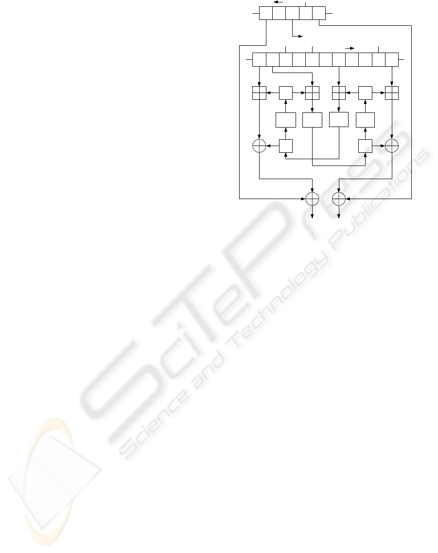
2.2 Nonlinear Function
The non-linear function of K2 v2.0 is fed the values
of two registers of FSR-A and four registers of FSR-
B and that of internal registers R1, R2, L1, L2, and
outputs 64 bits of the keystream every cycle. Fig. 2
shows the non-linear function of K2 v2.0. The non-
linear function includes four substitution steps that are
indicated by Sub.
The Sub step divides the 32-bit input string into
four 1-byte strings and applies a non-linear permuta-
tion to each byte using an 8-to-8 bit substitution, and
then applies a 32-to-32 bit linear permutation. The
8-to-8 bit substitution is the same as s-boxes of AES
(Daemen and Rijmen, 1998), and the permutation is
the same as AES Mix Column operation. The 8-to-
8 bit substitution consists of two functions: g and
f. The g calculates the multiplicative inverse modulo
of the irreducible polynomial m(x) = x
8
+ x
4
+ x
3
+
x+ 1 without 0x00, and 0x00 is transformed to itself
(0x00). f is an affine transformation defined by;
b
7
b
6
b
5
b
4
b
3
b
2
b
1
b
0
=
11111000
01111100
00111110
00011111
10001111
11000111
11100011
11110001
×
a
7
a
6
a
5
a
4
a
3
a
2
a
1
a
0
⊕
0
1
1
0
0
0
1
1
where a = (a
7
,...,a
0
) is the input and b = (b
7
,...,b
0
)
is the output, and a
0
and b
0
are the least significant bit
(LSB).
Let C be (c
3
,c
2
,c
1
,c
0
) and output D be
(d
3
,d
2
,d
1
,d
0
), where c
i
, d
i
are 8-bit values. The lin-
ear permutation D = p(C) is described as follows;
d
0
d
1
d
2
d
3
=
02 03 01 01
01 02 03 01
01 01 02 03
03 01 01 02
c
0
c
1
c
2
c
3
in GF(2
8
) of the irreducible polynomial m(x) = x
8
+
x
4
+ x
3
+ x+ 1.
2.3 Keystream Output
Let keystream at time t be Z
t
= (z
H
t
,z
L
t
) (each z
x
t
is a
32-bit value, and z
H
t
is a higher string). The keystream
z
H
t
, z
L
t
is calculated as follows:
z
L
t
= B
t
⊞ R2
t
⊕ R1
t
⊕ A
t+4
04910
R2
20
FSR-B
FSR-A
Keystream (64bits)
Dynamic Feedback Controller
L2
4
Sub
L1
Sub
R1
Sub
Sub
Figure 2: Non-Linear Function of K2 v2.0.
z
H
t
= B
t+10
⊞ L2
t
⊕ L1
t
⊕ A
t
where A
x
and B
x
denote outputs of FSR-A and FSR-
B at time x, and R1
x
, R2
x
, L1
x
, and L2
x
denote the
internal registers at time x. The symbol ⊕ denotes
bitwise exclusive-or operation and the symbol ⊞ de-
notes a 32-bit addition. Finally, the internal registers
are updated as follows;
R1
t+1
= Sub(L2
t
⊞ B
t+9
), R2
t+1
= Sub(R1
t
)
L1
t+1
= Sub(R2
t
⊞ B
t+4
), L2
t+1
= Sub(L1
t
)
where Sub(X) is an output of the Sub step for X.
2.4 Initialization Process
The initialization process of K2 v2.0 consists of
two steps, a key loading step and an internal state
initialization step. First, an initial internal state is
generated from a 128-bit initial key, a 192-bit initial
key, or a 256-bit initial key and a 128-bit initial
vector (IV) by using the key scheduling algorithm.
The key scheduling algorithm is similar to the round
key generation function of AES and the algorithm
extends the 128-bit initial key, the 192-bit initial
key or the 256-bit initial key to 384 bits. The key
scheduling algorithm for a 128-bit key is described as
SECRYPT 2008 - International Conference on Security and Cryptography
272
K
i
=
IK
i
(0 ≤ i ≤ 3)
K
i−4
⊕ Sub((K
i−1
≪ 8) ⊕ (K
i−1
≫ 24))
⊕Rcon[i/4− 1] (i = 4n)
K
i−4
⊕ K
i−1
(i 6= 4n)
where IK = (IK
0
,IK
1
,IK
2
,IK
3
) is the initial key, i
is a positive integer 0 ≤ i ≤ 11, and n is a positive
integer. The function Sub(X) in the key schedul-
ing algorithm is the same as that in the non-linear
function. This function is different from the round
key generation function of AES, and the other part
of the key scheduling algorithm is the same as
the AES round key generation. Rcon[i] denotes
(x
i
mod x
8
+ x
4
+ x
3
+ x+ 1,0x00, 0x00,0x00) and x
is 0x02. The internal state is initialized with K
i
and
IV = (IV
0
,IV
1
,IV
2
,IV
3
) as follows:
A
m
= K
4−m
(m = 0, ..., 4),B
0
= K
10
,B
1
= K
11
,
B
2
= IV
0
,B
3
= IV
1
,B
4
= K
8
,B
5
= K
9
,B
6
= IV
2
,
B
7
= IV
3
,B
8
= K
7
,B
9
= K
5
,B
10
= K
6
The internal registers, R1, R2, L1, and L2 are set to
0x00. After the above processes, the cipher clocks 24
times (j = 1, ..., 24), updating the internal states. The
internal states A
j+4
B
j+10
are also updated as follows:
A
j+4
=α
0
A
j− 1
⊕ A
j+2
⊕ z
L
j− 1
B
j+10
=(α
cl1
j−1
1
+ α
1−cl1
j−1
2
− 1)B
j− 1
⊕ B
j
⊕ B
j+5
⊕ α
cl2
j−1
3
B
j+7
⊕ z
H
j− 1
The recommended maximum number of cycles for
K2 v2.0 without re-initializing and re-keying is 2
58
cycles (2
64
keystream bits).
3 HARDWARE
IMPLEMENTATION OF K2
We considered two types of hardware implementa-
tions of K2 v2.0: a high speed implementations and a
compact size implementation.
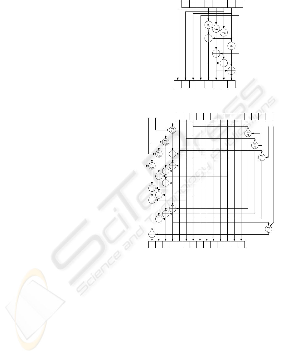
3.1 High Speed Implementation
K2 produces a 64-bit keystream for each cycle. To
improve the performance of hardware implementa-
tions, we considered both a double-keystream and
quad-keystream implementation of hardware; the
A
t
A
t+1
A
t+2
A
t+3
A
t+4
A
t+4
A
t+5
A
t+6
A
t+7
A
t+8
A
t-1
A
t-2
A
t-3
A
t+3
A
t+2
A
t+1
Figure 3: Quad-Keystream Implementation of LFSR-A.
B
t
B
t+1
B
t+2
B
t+5
B
t+4
B
t-1
B
t-2
B
t-3
B
t+6
B
t+7
B
t+8
B
t+9
B
t+10
B
t+1
B
t+2
B
t+5
B
t+4
B
t+6
B
t+7
B
t+8
B
t+9
B
t+10
B
t+11
B
t+12
B
t+13
B
t+14
B
t+3
B
t+3
Control Bits
Control Bits
Figure 4: Quad-Keystream Implementation of LFSR-B.
double-keystream implementation produces a 128-bit
keystream for each clock and the quad-keystream im-
plementation produces a 256-bit keystream for each
clock. The generated keystream bits are exclusive-
ored with a plaintext/ciphertext. To implement the
double-keystream circuit, one additional register for
LFSR-A, one additional register for LFSR-B, and
four additional internal memories are required to
cache data for a double-length keystream in each cy-
cle. The quad-keystream implementation also re-
quires three registers for each LFSR, and twelve addi-
tional internal memories performed in the same man-
ner.
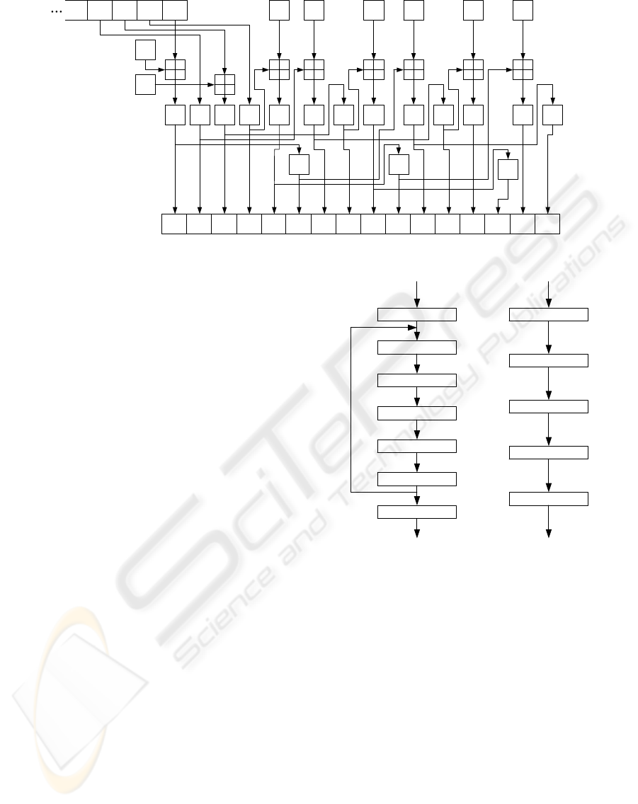
The whole circuit is parallelized using additional
circuit area, to generate double-length, quad-length
keystream per one clock cycle. Figures 3, 4, and 5
show the quad-implementation of LFSR-A, LFSR-B,
FPGA-TARGETED HARDWARE IMPLEMENTATIONS OF K2
273
B
t+4
L1
t+4
Sub
R2
t
L1
t+1
L1
t+2
B
t+9
L1
t+3
L2
t+1
R1
t+1
R2
t+1
L2
t+2
R1
t+2
R2
t+2
L2
t+3
R1
t+3
R2
t+3
L2
t+4
R1
t+4
R2
t+4
R1
t
L2
t
L1
t
R2
t-1
SubSubSub
B
t+5
Sub SubSub
Sub
B
t+10
Sub SubSub
Sub
B
t+11
Sub
B
t+6
B
t+7
SubSub
B
t+12
Sub
Figure 5: Quad-Keystream Implementation of Non-Linear Function.
and non-linear function, respectively.
The internal state values of LFSR-A, LFSR-B, and
internal memories (L1 L2 R1 R2) are updated to the
state values after four cycles by one clock cycle of the
implementation.
A 128-bit keystream Z
128
t
of the double-keystream
implementation for encryption/decryption is com-
puted as follows;
Z
128
t
= (z
H
t−1
,z
L
t−1
,z
H
t
,z
L
t
)
Similarly, a 256-bit keystream Z
256
t
of the quad-
keystream implementation for encryption/decryption
is computed as follows;
Z
256
t
= (z
H
t−3
,z
L
t−3
,z
H
t−2
,z
L
t−2
,z
H
t−1
,z
L
t−1
,z
H
t
,z
L
t
)
3.2 Compact Implementation
Rudra et. al. proposed a compact implementation
method for AES (Rudra et al., 2001). Their technique
involves mapping field elements to a composite field
representation. By using their technique, arithmetic
operations on GF(2
8
) elements are transformed into
operations in a composite field GF((2
4
)
2
). AES op-
erations translate to the composite field representation
as H(x) = Tx, where H denotes the mapping from
GF(2
8
) to GF((2
4
)
2
), and T denotes the correspond-
ing transformation matrix. That is, an 8-bit operation
in AES such as S-box is performed as 4-bit opera-
tions. Thus, the implementation size of the algorithm
can be reduced by using their techniques.
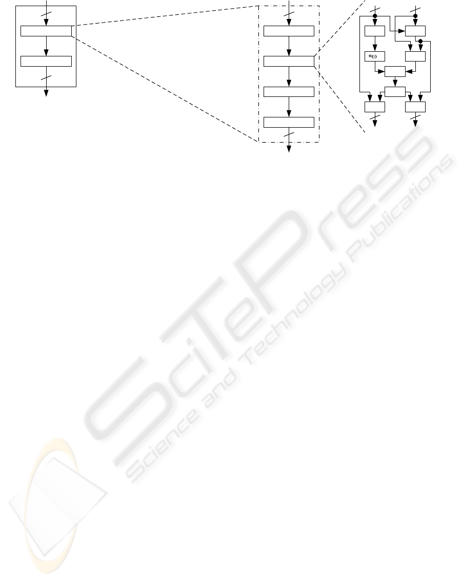
We apply their technique to a part of the non-linear
function of K2 as shown Figure 6. We add matrixes
on data paths of the substitution of K2. Input val-
ues of the inverse operations are transformed into the
elements of the composite field by the matrix T and
Affine Trans.
T
T
-1
Inverse Calc
Mix Column
T
Inverse Calc
Affine Trans.
Mix Column
Shift Rows
Add Round Key
T
-1
ΦΕΣΒ͑ΖΥ͑͟ΒΝ͑͟Τ͑ͲͶ΄͑
ͺΞΡΝΖΞΖΟΥΒΥΚΠΟ
ΦΣ͑ͺΞΡΝΖΞΖΟΥΒΥΚΠΟ͑
ΗΠΣ͑ͼͣ͑Χͣ͟͡
Figure 6: Non-Linear Function Architectures Transformed
in the Composite Field.
its inverse matrix T
-1
re-transform into the elements
of GF(2
8
). The matrixes are an 8 × 8 transforma-
tion. Data in the inverse operation is defined as an
element of the composite field GF((2
4
)
2
), and data
out of the inverse operation is computed as an ele-
ment of GF(2
8
). The matrixes T and T
-1
are defined
by;
T =
10100000
10101100
11010010
01110000
11000110
01010010
00001010
11011101
T
−1
=
00100100
11101110
10100100
01011010
10110010
01110010
10110000
01010001
SECRYPT 2008 - International Conference on Security and Cryptography
274
+X^2
14
C
+
X
-1
CC
upper lower
4 4
44
upper lower
Inverse Calc.
Affine Trans.
;
8
8
Substitution
Mix Column
32
32
Sub
T
T
-1
Figure 7: K2 Sub Operation Architecture Transformed in the Composite Field.
The Sub consists of substitutions and the Mix Col-
umn. The substitutions involve an inverse calculation
and affine transformation. We transform all inverse
operations that are located inside the substitution of
the non-linear function into inverse operations in the
composite field. The method used for transformation
is similar to the method proposed by Rudra et. al..
They apply the method to all operations of the round
function of AES. On the other hand, we apply the
method only to the inverse operations. In AES imple-
mentations, the round function is used many times for
producing encrypted/decrypted data. However, each
Sub operation in the non-linear function are used once
for one keystream generation in K2 implementations.
Thus, the method should be applied only to inverse
operation for efficient and conpact implementations
of K2. We transform the Sub that is an 8-bit oriented
operation into a 4-bit oriented operation in the com-
position field GF((2
4
)
2
) as follows.
An inverse X
−1
of an input value X is defined as;
X = r
0
λ+ r
1
, (r
0
,r
1
∈ GF(2
4
))
X
−1
= s
0
λ+ s
1
(s
0
,s
1
∈ GF(2
4
))
where λ is a generator of GF((2
4
)
2
). In this condi-
tion, we can calculate X
−1
as follows;
s
0
= (r
0
+ r
1
)∆
−1
, s
1
= r
1
∆
−1
where ∆ = r
0
(r
0
+ r
1
) + ω
14
r
2
1
and ω is a generator
of GF(2
4
). An inverse operation of elements x in
GF(2
4
) is implemented as a 4-bit-input 4-bit-output
table. The affine transformation and Mix Column op-
erations are the same as the original operations of K2.
Figure 7 shows the Sub operation architecture
transformed in the composite field. The architecture
consists of calculation units: squaring, multiplication,
addition, multiplication of ω, 4-bit inverse operation,
and exclusive-or of 4 bit values. The size of the 4-
bit inverse operation is much smaller than the size of
the 8-bit inverse operation. Thus, we can construct a
compact implementation if these calculation units are
shared by each operation and used to switch a pair of
input and output values.
4 EVALUATION RESULT
In this section, we present the evaluation results of
hardware implementations using an FPGA simula-
tor. We implemented the K2 stream cipher targeted
toward the Xilinx Spartan-II, Spartan-3, and Virtex-
II FPGAs. The circuit sizes of implementations of
normal, double-keystream, and quad-keystream im-
plementations are larger than the capacity of Spartan-
2, and thus, we evaluated normal, double, and quad-
keystream implementations on Spartan-3. We also
evaluated normal implementations on Virtex-II. The
compact implementation is evaluated on Spartan-II,
Spartan-3, and Virtex-II. We use Xilinx ISE 9.1 for
post-place and route simulation and static timing anal-
ysis.
Table 1 and Table 2 show the evaluation results
of high speed and compact implementations. Data
rate, clock frequency, throughput, and area denote the
number of bits that the cipher generates for each cy-
cle, maximum clock frequency of the circuit, maxi-
mum throughput of encryption/decryption estimated
by the maximum clock frequency, and the number of
slices of the circuit, respectively. The reduction rates
shown in Table 2 are calculated as 100× (N − M)/N,
where N is the number of slices of the normal imple-
mentation of devices and M is the number of slices
of the compact implementation for the same devices.
FPGA-TARGETED HARDWARE IMPLEMENTATIONS OF K2
275

Table 1: Evaluation Results of High Speed Implementations on FPGA.
Design Data rate Clock Freq. Throughput Area Throughput/Area Device
(bits/cycle) (MHz) (Mbps) (slice) (Mbps/slice)
Normal 64 63.9 4090 3067 1.33 Spartan-3
Double-keystream 128 38.0 4864 5295 0.92 Spartan-3
Quad-keystream 256 20.4 5223 9161 0.57 Spartan-3
Normal 64 74.8 4787 2898 1.65 Virtex-II
Table 2: Evaluation Results of Compact Implementations on FPGA.
Target Data rate Clock Freq. Throughput Area Throughput/Area Reduction Rate
(bits/cycle) (MHz) (Mbps) (slice) (Mbps/slice) (%)
Spartan-II 64 30.0 1920 2133 0.90 -
Spartan-3 64 39.1 2503 2140 1.17 30.2
Virtex-II 64 48.7 3117 2145 1.45 26.0
Table 3: Comparisons with FPGA Implementations of Other Ciphers.
Algorithm Key Length Throughput Area Through./Area Normalized Device
(bit) (Mbps) (slice) (Mbps/slice) Efficiency
Trivium (Good et al., 2006) 80 102 40 2.55 0.80 Spartan-II
Grain (Good et al., 2006) 80 105 48 2.19 0.69 Spartan-II
Phelix (Good et al., 2006) 256 750 1077 0.70 0.70 Spartan-II
Edon80 (Kasper et al., 2006) 80 1.87 50 0.04 0.01 Spartan-3
DECIM v2 (Hwang et al., 2008) 80 46.25 80 0.58 0.18 Spartan-3
F-FCSR-H v2 (Hwang et al., 2008) 80 1104 342 3.23 1.01 Spartan-3
Pomaranch (Hwang et al., 2008) 80 49 648 0.08 0.03 Spartan-3
MICKEY-128 (Bulens et al., 2007) 128 200 190 1.05 0.53 Virtex-II
A5/1 (Galanis et al., 2004) 64 188.3 32 5.88 1.47 Virtex-II
RC4 (Galanis et al., 2004) 256 120.8 140 0.86 0.86 Virtex-II
E0 (Galanis et al., 2004) 128 189 895 0.21 0.11 Virtex-II
AES-128 (Good and Benaissa, 2005) 128 2.2 264 0.01 0.005 Spartan-II
AES-128 (Chodowiec and Gaj, 2003) 128 69 522 0.13 0.07 Spartan-II
AES-128 (Rouvroy et al., 2004) 128 87 1231 0.07 0.04 Spartan-3
AES-128 (Standaert et al., 2003) 128 1563 2257 0.69 0.35 Virtex1000
K2 Compact (this paper) 256 1920 2133 0.90 0.90 Spartan-II
K2 Normal (this paper) 256 4090 3067 1.33 1.33 Spartan-3
K2 Double− keystream (this paper) 256 4864 5295 0.92 0.92 Spartan-3
K2 Quad −keystream (this paper) 256 5223 9161 0.57 0.57 Spartan-3
We also evaluated the efficiency of the implementa-
tions by dividing the throughput by the area, which is
the same index used in previous studies.
The quad-keystream implementation is expected
to achieved 5 Gpbs on the Spartan-3 FPGA imple-
mentation. From the comparison of normal, double-
keystream, and quad-keystream implementations, we
showed that the rate of increase of area size is higher
than the rate of increase of throughput by using the
parallelization approach described in 3.1. The normal
implementation was shown to be the most efficient
among our implementation. The compact implemen-
tation technique reduces 30.2% of slices on Spartan-
3, and 26.0% of slices on Virtex-II.
Comparisons with previously published evalua-
tion results of FPGA implementations for other ci-
phers are shown in Table 3. The column of key length
denotes a key length of each algorithm. There is a
tradeoff between the performance of the algorithm
and its security level (effective key length). Thus, we
compare an index ”Normalized Efficiency”. The in-
dex is calculated as (T × L)/(S × 256), where T, S,
and L denote the throughput, the area size, and the
key length respectively.
The throughput of K2 is much faster than other
block/stream ciphers, even though the circuit size is
large. In terms of efficiency, the implementations of
K2 has high efficiency when compared with other
stream ciphers, and is 4-10 times higher than AES
implementations. The FPGA implementation of K2
is suitable for applications that require high speed en-
cryption/decryption and accepts medium size circuits
for hardware implementations.
SECRYPT 2008 - International Conference on Security and Cryptography
276

5 CONCLUSIONS
This paper presented the evaluation results of sev-
eral FPGA implementations of K2 v2.0: high
speed implementations and compact implementa-
tions. The quad-keystream implementation is ex-
pected to achieved 5 Gbps on a Spartan-3 FPGA im-
plementation, and the circuit size of the compact im-
plementation of K2 is 2133 on Spartan-II. Further-
more, we evaluated the efficiency of the implementa-
tions using two benchmarks: throughput per area and
the normalized efficiency. The implementationsof K2
has high efficiency compared with other stream ci-
phers, and its efficiency is 4-10 times higher than AES
implementations. The evaluation results suggested
that the FPGA implementation of K2 is suitable for
applications using high speed encryption/decryption.
REFERENCES
Bulens, P., Kalach, K., Standaetes, F. X., and Quisquater,
J. J. (2007). FPGA implementations of estream phase-
2 focus candidates with hardware profile. In SASC
2007 Workshop Record, pages 205–214. eSTREAM
Project.
Chodowiec, P. and Gaj, K. (2003). Very compact FPGA
implementation of the AES algorithm. In Proc.
of CHES’03, LNCS, volume 2779, pages 319–333.
Springer Verlag.
Daemen, J. and Rijmen, V. (1998). The Design of Rijn-
dael, Information Security and Cryptography, Texts
and Monographs. Springer Verlag.
Ekdahl, P. and Johansson, T. (2000). SNOW -a new stream
cipher. The NESSIE submission paper.
Galanis, M. D., Kitsos, P., Kostopoulos, G., and
Koufopavlou, O. (2004). Comparison of the perfor-
mance of stream ciphers for wireless communications.
In Proc. of CCCT’04, pages 113–118.
Good, M. and Benaissa, M. (2005). AES on FPGA from the
fastest to the smallest. In Proc. of CHES’05, LNCS,
volume 3659, pages 427–440. Springer Verlag.
Good, T., Chelton, W., and Benaissa, M. (2006). Review
of stream cipher candidates from a low resource hard-
ware perspective. In SASC 2006 Workshop Record.
eSTREAM Project.
Hwang, D., Chaney, M., Karanam, S., Ton, N., and Gaj,
K. (2008). Comparison of FPGA-targeted hardware
implementations of eSTREAM stream cipher candi-
dates. In SASC 2008 Workshop Record, pages 151–
162. eSTREAM Project.
Kasper, M., Kumar, S., Lemke-Rust, K., and Paar, C.
(2006). A compact implementation of edon80. eS-
TREAM Report 2006/057.
Kiyomoto, S., Tanaka, T., and Sakurai, K. (2007a). K2: A
stream cipher algorithm using dynamic feedback con-
trol. In Proc. of SECRYPT 2007, pages 204–213. IN-
STICC PRESS.
Kiyomoto, S., Tanaka, T., and Sakurai, K. (2007b). A word-
oriented stream cipher using clock control. In SASC
2007 Workshop Record, pages 260–274. eSTREAM
Project.
Rodr´ıguez-Henr´ıquez, F., Saqib, N. A., D´ıaz-Perez, A., and
Koc, C. K. (2007). Cryptographic algorithms on re-
configurable hardware. Signals and Communication
Technology, Springer.
Rose, G. and Hawkes, P. (1999). The t-class of SOBER
stream cipher. Publication Document, QUALCOMM
Australia.
Rouvroy, G., Standaert, F. X., Quisquater, J. J., and
Legat, J. D. (2004). Compact and efficient encryp-
tion/decryption module for FPGA implementation of
the AES Rijndael very well suited for small embedded
applications. In Proc. of ITCC 2004, volume 2, pages
583–587.
Rudra, A., Dubey, P. K., Julta, C. S., Kumar, V., Rao, J. R.,
and Rohatgi, P. (2001). Efficient rijndael encryption
implementation with composite field arithmetic. In
Proc. of CHES’01, LNCS, volume 2162, pages 171–
184. Springer Verlag.
Standaert, F. X., Rouvroy, G., Quisquater, J.-J., and Legat,
J.-D. (2003). Efficient implementation of rijndael en-
cryption in reconfiqurable hardware: Improvements
and design tradeoffs. In Proc. of CHES’03, LNCS,
volume 2779, pages 334–350. Springer Verlag.
FPGA-TARGETED HARDWARE IMPLEMENTATIONS OF K2
277
