
A
SOURCE CODE BASED MODEL TO GENERATE GUI
GUI Generation based on Source Code with Declarative Language Extensions
Marco Monteiro
School of Technology and Management, Polytechnic Institute of Leiria, Leiria, Portugal
Paula Oliveira, Ramiro Gonc¸alves
Engineering Department, University of Tr
´
as-os-Montes e Alto Douro, Vila Real, Portugal
Keywords:
Attribute-Oriented Programming, Source Code Model, GUI Generation, Data-Driven Application.
Abstract:
Due to data-driven application nature and its increasing complexity, developing its user interface can be a
repetitive and time-consuming activity. Consequently, developers tend to focus more on the user interface
aspects and less on business related code. In this paper, we present an alternative approach to graphical user
interface development for data-driven applications, where the key concept is the generation of concrete graph-
ical user interface from a source code based model. The model includes the original source code metadata
and non-intrusive declarative language extensions that describes the user interface structure. Some Object
Relational Mapping tools already use a similar concept to handle interoperability between the data layer and
the business layer. Our approach applies the same concept to handle business and presentation layer inter-
operability. Also, concrete user interface implementation will be delegated to specialized software packages,
developed by external entities, that provide complete graphical user interfaces services to the application.
When applying our approach, we expect faster graphical user interface development, allowing developers to
refocus on the source code and concentrate their efforts on application core logic.
1 INTRODUCTION
In this paper we propose an alternative approach to
Graphical User Interface (GUI) development for data-
driven applications. Nowadays developers tend to
create GUI by composition of various components.
Our final goal is to allow developers to define GUI
by adding non-intrusive declarative language exten-
sions to the original source code and then acquire an
external software package to which they delegate the
implementation of the concrete GUI.
We start by introducing the research problem on
section 2 and attribute oriented programming on sec-
tion 3, followed by a description of the proposed
model on section 4 and conclusions on section 5.
2 OVERVIEW
Currently, a large number of projects use Component
Based Development (CBD), which allows application
development by assembling a set of pre-manufactured
components. Each component is a black-box entity,
which can be deployed independently and is able to
deliver specific services (Szyperski, 1998).
GUIs are composed of various graphical elements,
such as buttons or input fields. When developing
GUIs, both the presentation and behavior aspects of
those elements are to be considered. Presentation
aspects concern the appearance and layout of GUI
elements and behavior is related to the interaction
between themselves or between them and the un-
derlying code. Using CBD, each GUI element is
mapped to a component and presentation or behav-
ior aspects are defined by its properties, methods and
events. Also, by using Rapid Application Develop-
ment (RAD) tools, GUI layout design is made visu-
ally through composition of components. Compared
to older processes the advent of CBD and RAD tools
has increased GUI development productivity.
However, CBD still has not redeemed its promises
of reuse and flexibility (Bruin and Vliet, 2002) and
there is still a lot of risks, challenges and unresolved
issues in CBD (Vitharana, 2003). One of those is-
21
Monteiro M., Oliveira P. and Gonçalves R. (2008).
A SOURCE CODE BASED MODEL TO GENERATE GUI - GUI Generation based on Source Code with Declarative Language Extensions.
In Proceedings of the Third International Conference on Software and Data Technologies - PL/DPS/KE, pages 21-28
DOI: 10.5220/0001878600210028
Copyright
c
SciTePress
sues is related to the process of component composi-
tion and configuration. On large or very large appli-
cations, the same component can be reused several
times on different contexts, which is the main fac-
tor for the productivity improvement accomplished by
CBD. However, as the number of instances and com-
plexity of components increases, developer’s time is
increasingly spent on the tedious tasks of compos-
ing layouts, configuring components and maintain-
ing consistency in presentation and behavior aspects
of the GUI components through the entire applica-
tion. Developers tend to focus more on GUI aspects
and components internals and less on application core
logic or business related code.
User Interface (UI) is always an important aspect
of any application that requires some kind of user in-
teraction. There are applications where UI is the most
critical factor for their success. In these cases, de-
velopers must focus their time and resources to the
development of GUI related features, in order to cre-
ate rich and innovative user experiences. However,
in most applications, although UI still plays an im-
portant role, it is the core business functionalities that
decide their success or failure. Therefore, it is impor-
tant to refocus development time and resources to the
core functionalities, while still producing rich enough
GUIs. This is particulary true for most data-driven
applications produced today.
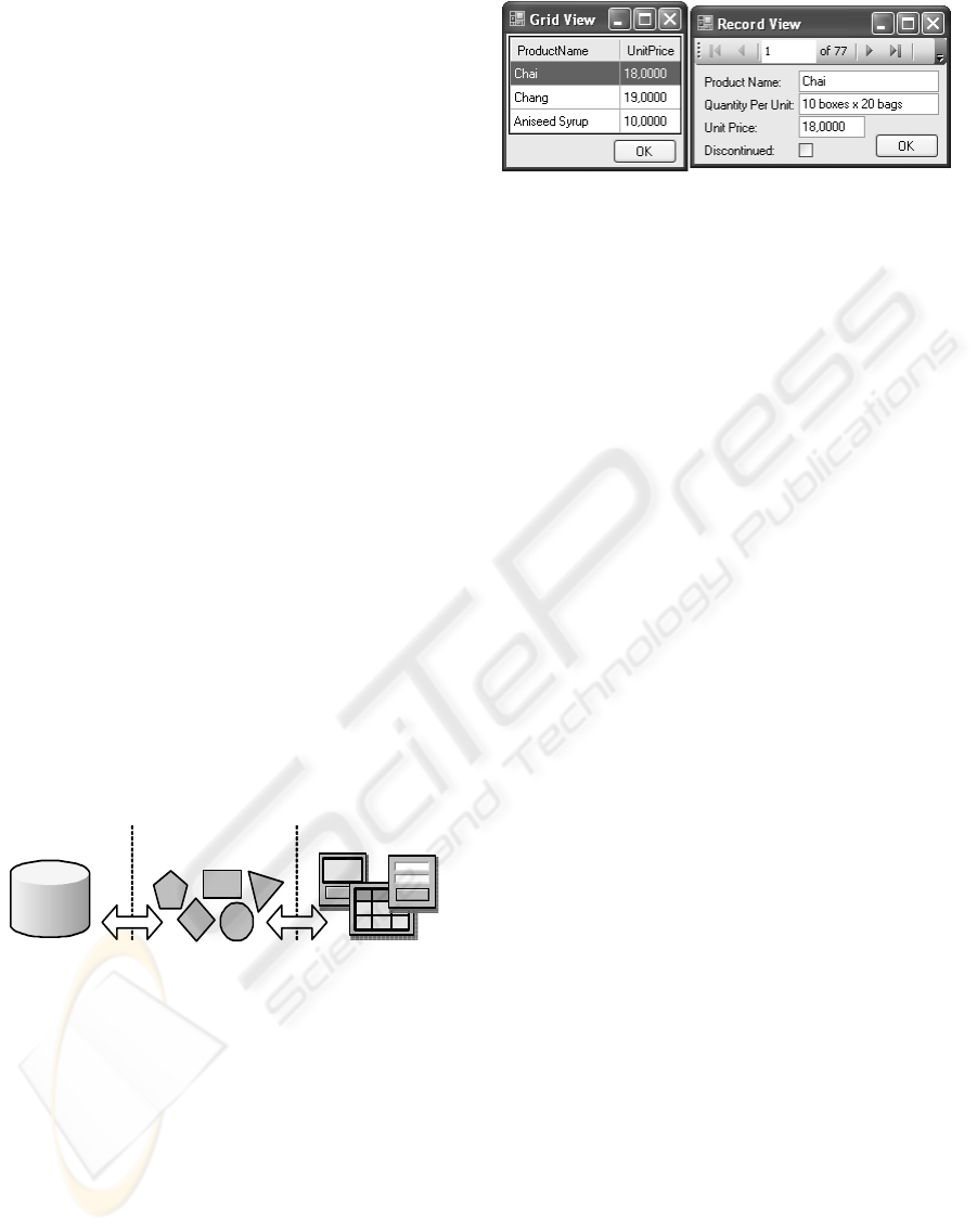
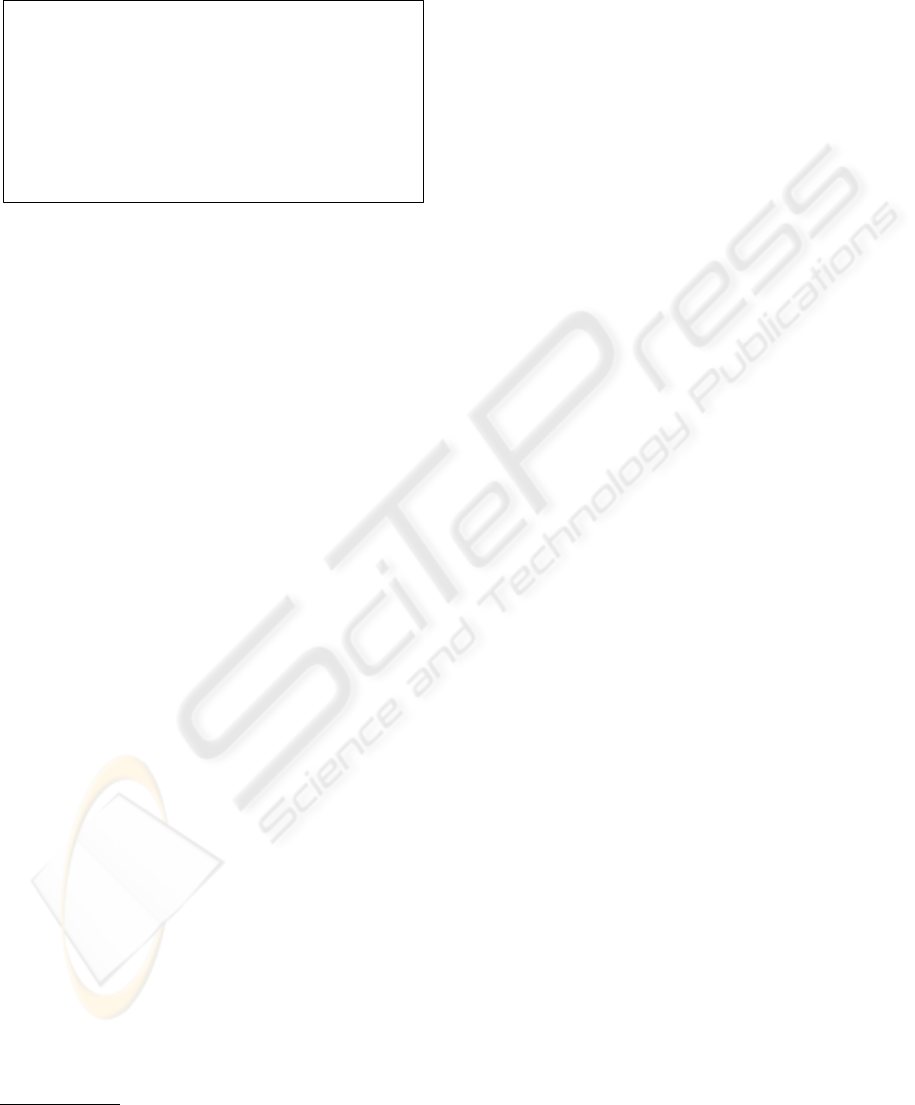
In this article, we consider data-driven applica-
tions as applications that allow users to access and
manipulate large amounts of complex data, usually
located on data repositories (Figure 1).
PresentationBusiness Code
(Core Logic)
Data Repository
Figure 1: Data-driven applications.
The type of application device, whether is a win-
dows, web or PDA and its architecture (client/server,
three layers, multi-layer) is irrelevant in this context.
It is also irrelevant the type of data repository used, al-
though relational database servers have been almost a
standard, there are other valid options, such as eXten-
sible Markup Language (XML) or object based data
repositories. No matter how or where data comes
from, as long as applications devices follows GUI
paradigm, data presentation and manipulation follows
some patterns that are easily recognizable. For ex-
ample, there are two typical ways of presenting data:
record views and grid views. Record views allows
the presentation of all attributes of only one entity
Figure 2: Grid and Record View.
instance, while grid views usually presents the most
relevant attributes of various instances simultaneously
(Figure 2).
GUI related components improves development
productivity by capturing the presentation and behav-
ior aspects of these patterns. However, data structure
for this type of application can be very complex, rep-
resenting hundreds or even thousands of different en-
tities. For each entity, slightly different views are re-
quired, even though they are all similar as they follow
the same patterns. Every view requires new compo-
sitions and configurations of the same components,
which multiplied by all of them implies a major in-
crease on developer’s effort. Also, the huge number
of different views increases the risk of breaking appli-
cation GUI consistency.
The main goal for the solution we are proposing
is to improve GUI development by reducing or elimi-
nating the need to configure every different view. In-
stead, we aim at propagating global configurations
through the entire application. There are some so-
lutions for this problem, like Cascade Style Sheets
(CSSs), templates, specialized or custom frameworks
and automatic GUI generation. This last alternative
will be briefly described in the next section.
2.1 Automatic GUI Generation
Automatic generation is potentially the most produc-
tive method to develop GUI, since by definition it al-
lows developers to delegate GUI creation to an exter-
nal software package. Most of the research made in
this area is pursuing the generation of GUI for various
devices, where each device implies a set of restric-
tions. Multiplatform GUI can already be developed
by using portable languages like Java or HTML, but
that does not solve the problem of fitting the same ap-
plication on different devices with different capabili-
ties (Jelinek and Slavik, 2004). Proposed solutions to
generate GUI automatically are mainly model-based
systems, that attempt to formally describe the tasks,
data, and users that an application will have, and
then use this formal models to guide the generation
of the GUI. Some systems automatically design the
GUI and others provide design assistance to develop-
ICSOFT 2008 - International Conference on Software and Data Technologies
22

ers (Nichols and Faulring, 2005). These models are
abstract models, meaning that they do not specify ex-
actly how the GUI is going to look, but rather what el-
ements are to be shown and how they should behave.
Systems will then use that abstract description to gen-
erate concrete interfaces for various devices. The fact
that those devices can have very different capabilities
is what makes automatic GUI generation so complex.
Different models can have different levels of ab-
straction. The more abstract a model is, the more flex-
ible the system can be. By contrast, when a model is
less abstract and therefore closer to the concrete GUI,
flexibility is lost but system implementation is easier
and usually produce better results. Currently, most of
those abstract models, as well as some concrete GUI
description languages, are XML based.
Despite a lot of research, model-based automatic
GUI generation still has not become common in GUI
development, in part because building models is an
abstract process and better results are often achievable
by a human designer in less time (Myers et al., 2000).
Abstract models can be complex to build and main-
tain, thus keeping models and applications concrete
GUI synchronized can be problematic, as changes
made on the model must reflect on the concrete GUI
and vice versa. Due to the lack of tools, this process
is even more complex, specially compared to current
visual editors integrated on RAD tools.
There are also some commercial tools, like Oracle
Designer, that generate not only the GUI but complete
applications, embracing all development cycle, which
is not appropriate to development methodologies like
extreme programming (Beck, 1999), where constant
changes and very fast prototyping are required. They
are usually based on relational databases, and use its
metadata to generate layouts for data representation.
However, resulting applications have behavior limi-
tations, because relational databases are typically re-
stricted to create, retrieve, update and delete (CRUD)
operations.
3 ATTRIBUTE ORIENTED
PROGRAMMING
Attribute oriented programming is a program-level
marking technique, that allows developers to mark
language elements (e.g. classes, methods, and prop-
erties) in the source code, to indicate that they main-
tain application or domain specific semantics. By
hiding the implementation details of those seman-
tics from source code, attributes increase the level
of programming abstraction and reduce programming
complexity, resulting in simpler and more readable
programs (Wada and Suzuki, 2005). These markers
or attributes, extend application metadata by adding
declarative information to entities. This extended
metadata can be retrieved at runtime to control how
the program interacts with services defined by the ap-
plication or specific model (Newkirk, 2002). Also,
attributes can change application runtime behavior by
transforming its logic, with the assistance of a sup-
porting generation engine, that transform language el-
ements associated with attributes into more detailed
program code. Dependencies on the underlying mid-
dleware are thus replaced by attributes, acting as weak
references. This means that the evolution of the un-
derlying middleware is taken into account by the gen-
eration engine and the program code is left unchanged
(Rouvoy and Merle, 2006).
//.Net Attribute (WebMethod)
[WebMethod]
public int double(int a) { . . . }
//Java Annotation (entity)
@entity
class book { . . .}
Figure 3: Example of .Net attribute and Java annotation.
With the advent of .Net attributes and Java an-
notations (Figure 3), attribute oriented programming
is now an widespread technique, used in several do-
mains. Some of this are broad-range domains, like
logging, web services, persistence or security, while
others are specific domains, such as fault-tolerance
(Schult and Polze, 2002) or system level modeling
and simulation environment (Lapalme et al., 2004),
among many others.
The typical data driven application, uses a rela-
tional database on the data layer and objects on the
business code layer (Figure 1), which creates a prob-
lem known as object-relational impedance mismatch,
derived from the fact that object-oriented and rela-
tional paradigms represent information in manners
that are quite different from each other, resulting in
two different models for representing the same infor-
mation (Lodhi and Ghazali, 2007). One of the solu-
tions to the impedance mismatch problem, is the use
of Object Relational Mapping (ORM) tools, that pro-
vide a mapping between the object model and the re-
lational model, acting as an intermediary between an
object oriented code base, and a relational database.
On ORM tools, mapping configuration is needed to
define how data is transformed from object to rela-
tional data and vice versa. On some of those tools,
like Hibernate Annotations
1
, Castle ActiveRecord
2
1
http://annotations.hibernate.org
2
http://www.castleproject.org/activerecord/index.html
A SOURCE CODE BASED MODEL TO GENERATE GUI - GUI Generation based on Source Code with Declarative
Language Extensions
23
(Figure 4) or DevExpress Persistent Objects for .Net
3
,
mapping configuration is implemented directly on the
source code using attributes, thus avoiding external
configuration resources.
[ActiveRecord]
class Category: ActiveRecordBase
{ ...
[PrimaryKey]
public int Id {...}
[Property]
public string Name {...}
[HasMany]
public IList<Category> SubCategories {...}
... }
Figure 4: Example of Castle ActiveRecord attributes.
When mapping configuration is done directly in
the source code, it is possible for the developer to con-
centrate only on the object-oriented paradigm and al-
low ORM tools to handle all persistence details. Inter-
operability between data and business code layers and
the creation and maintenance of relational data model,
can be the responsibility of a concrete ORM tool. Re-
focusing developer’s time and resources back to the
source code, seams to us like a very interesting con-
cept, which leads us to the following question “why
we do not apply the same principles for the interop-
erability between business code and presentation lay-
ers”? This is the question that droves us to study and
propose the solution presented in next section.
4 PROPOSED MODEL
The key concept behind our approach is the auto-
matic generation of concrete GUIs from source code
based models, as opposed to the use of specialized
GUI models. The main advantage of source code
based models is the proximity between the model and
the code we want to execute, improving the integra-
tion and interaction between application core logic
or business code and application GUI. Also, the pro-
cess of model creation is quicker and maintenance is
simpler, because part of the model is already defined
by original source code and synchronization between
business code and GUI model is no longer required.
However, mixing business and GUI related aspects
in the same code modules, is against separation of
concerns principle and could induce the cluttering
of source code with GUI related details. To avoid
or minimize those problems, the model will be de-
fined by extending a programming language with new
3
http://www.devexpress.com/Products/NET/Libraries/
XPO/
declarative elements (implemented with attributes),
that will describe only structural information about
the GUI. Since these new elements are only declar-
ative, they will not interfere with original structures
or execution flows. In fact, if compiled without acti-
vating the GUI model, the final source code that in-
cludes the new declarative elements, should produce
a binary module with similar functionalities and be-
havior when compared with the original source code.
4.1 System Architecture
Although is not a common technique, using the source
code as a model to generate GUI is not original. For
instance, in 2004 Jelinek (Jelinek and Slavik, 2004),
used annotated source code to generate GUI. Despite
some identical concepts, Jalinek model uses a tree-
rewrite based language, as our model will use a main-
stream language, which simplifies the reuse of avail-
able GUI components and the development of com-
mercial business applications. We use C#, but all
main concepts are also applicable to the Java language
or any other language with annotations.
There are two characteristics on our solution, that
distinguish it from others. First, the referred source
code based model, that incorporates declarative lan-
guage extensions, which we call Graphical User In-
terface Language eXtensions (GUILX). The model,
named GUILX Model, includes the original source
code and the GUILX language extensions. Second,
instead of implementing concrete GUI generation, ei-
ther automatically or semi-automatically, system will
delegate that responsibility to external software pack-
ages, which we call Smart Templates. Therefore, the
GUILX Model is kept independent from concrete im-
plementation, making it possible for the developer to
choose the most appropriated GUI to a specific appli-
cation, by acquiring a particular Smart Template. In
order to keep independency between this two parts,
the model and the Smart Template will be connected
through an extra middleware layer, that will act as a
buffer and handle interaction between them. We call
the extra layer, the Binding Framework. These three
layers will be further analyzed on section 4.1.1.
To better comprehend the model, let us analyze
data-driven applications. In those applications, GUI
elements such as textboxs or grids, provide data for
the user to read or write. Also, users can perform op-
erations by activating events on GUI elements, like
clicking on a button or a menu item. Comparing this
reality with object-oriented languages, such as C#,
there are some similarities, as objects also have data,
which can be encapsulated as properties and have
operations called methods. Objects data and behav-
ICSOFT 2008 - International Conference on Software and Data Technologies
24
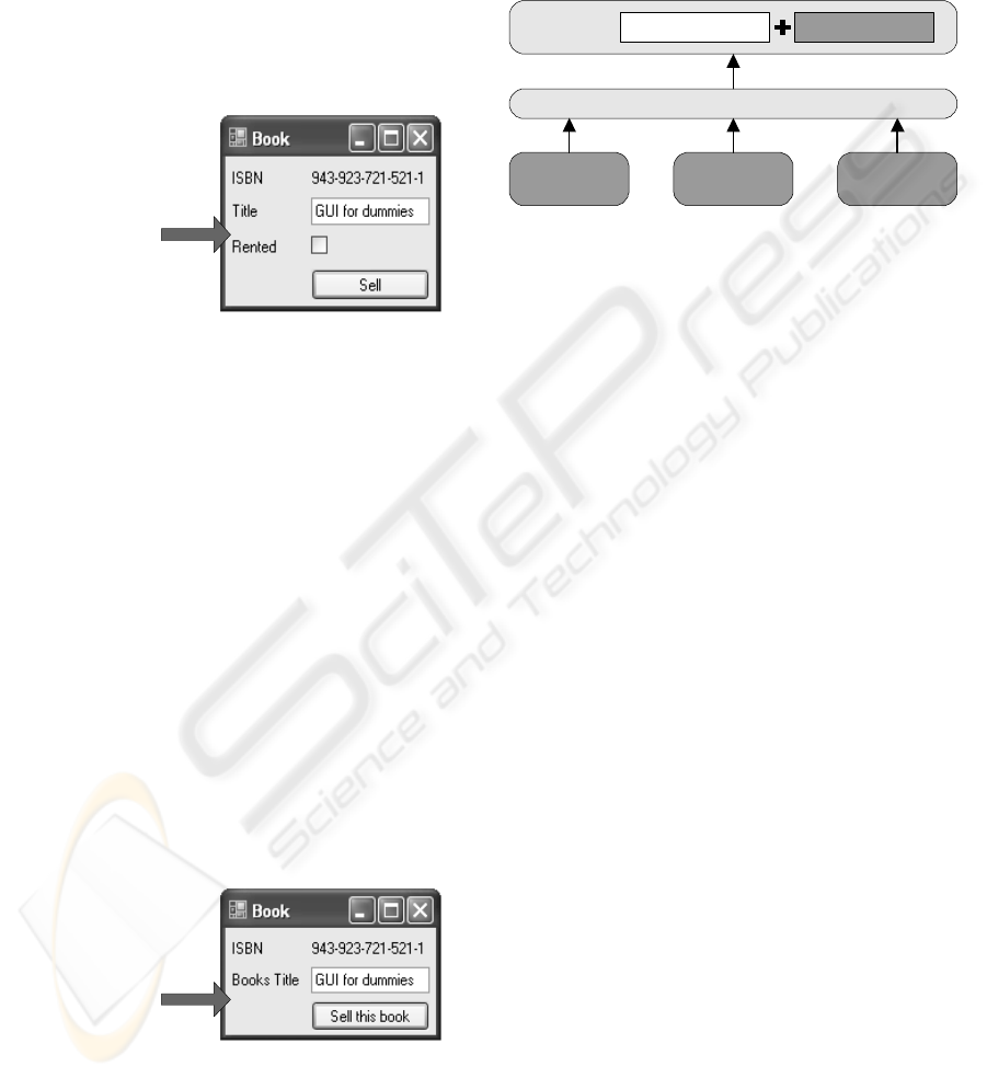
ior can be mapped in GUI elements. For example,
consider a business class called “Book” with a read-
only string property called “ISBN”, a string property
called “Title”, a boolean property called “Rented” and
a method called “Sell”. By analyzing source code at
runtime through application metadata, we can gener-
ate the GUI elements and layout needed to represent
instances of Book objects. GUI elements are chosen
by the kind of language elements and accordingly to
properties types and accessibility (Figure 5).
public class Book {
public string ISBN
{ get {...} }
public string Title
{ get {...}
set {...} }
public bool Rented
{ get {...}
set {...} }
public void Sell {...}
}
Figure 5: Generation GUI from source code.
Although language metadata has already some
useful information, it is not enough for defining a
model to generate GUI. Filling this gap is GUILX
language extensions responsibility, by enriching the
metadata with structural information about GUI. This
extensions are implemented by annotating the source
code through .Net custom attributes. “Show” is the
first attribute defined on GUILX, indicating which
language elements are meant to be available and with
what description. If we analyze a second example
in (Figure 6) and compare it with the first one, we
can verify that the checkbox is not shown because
“Rented” property does not have the “Show” attribute.
Also, “Title” property and “Sell” method have differ-
ent descriptions.
public class Book {
[Show]
public string ISBN
{ get {...} }
[Show("Books title")]
public string Title
{ get {...}
set {...} }
public bool Rented
{ get {...}
set {...} }
[Show("Sell this book")]
public void Sell() {...}
}
Figure 6: Usage of GUILX “Show” attribute.
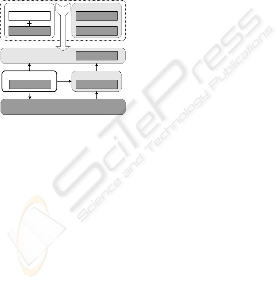
4.1.1 System Layers
System conceptual architecture (Figure 7) is com-
posed by three parts or layers: the GUILX Model, the
Binding Framework and Smart Templates, which we
describe in this section.
GUILX Model
Smart
Template (A)
GUILX ExtensionsBusiness Code (C#)
Binding Framework
Smart
Template (B)
Smart
Template (Z)
...
Figure 7: Conceptual architecture.
GUILX Model incorporates both the original
source code and GUILX language extensions or at-
tributes. Most of this model is already shaped by orig-
inal source code, simplifying its creation and mainte-
nance process as opposed to an external specialized
model. Language extensions should be as simple as
possible, in order to comply with separation of con-
cerns principle and to avoid cluttering source code
with GUI related details. Only structural GUI in-
formation must be defined in the source code. Con-
crete GUI details, if applied, should be defined out-
side the source code by Smart Templates. However,
the GUILX Model must be rich enough to ensure that
a functional prototype (even if a very simple one) can
be created.
The Binding Framework is responsible for
the interoperability between Smart Templates and
GUILX Model, so that these two layers do not in-
teract directly, thus keeping them independent from
each other. It allows the Smart Template to query the
GUILX Model metadata, to create object instances
and to invoke methods of that objects. Also, it serves
as a controller, maintaining the execution context for
the GUI elements, thus controlling navigation through
entire application.
The solution architecture is designed to support
various Smart Templates, one at a time. The idea is
that of allowing developers to define a GUILX Model
and then acquire a Smart Template to which they del-
egate all GUI implementation. Smart Templates are
specialized frameworks, developed by external enti-
ties that provide complete GUI services to the GUILX
Model. There can be Smart Templates developed
by different suppliers, for different devices and using
completely different methods. One can generate GUI
automatically, other can generate GUI partially and
another can create GUI from manual definitions.
A SOURCE CODE BASED MODEL TO GENERATE GUI - GUI Generation based on Source Code with Declarative
Language Extensions
25
4.2 System Implementation
To prove the viability of our proposed solution, a prof-
of-concept was developed on Microsoft .Net Frame-
work using C# language. Due to .Net multi-language
support, it can be integrated with other .Net compat-
ible languages. In this section, we describe the solu-
tion concrete architecture (Figure 8) and some related
technical issues.
Core
Business Library
GUILX Extensions
Business Code (C#) GUILX Core
PostSharp
Concrete GUILX Model
Code Weaving
Binding Framework
GUILX Binder
Application with GUI
GUILX Controller
Smart Template
GUILX Common
Figure 8: GUILX concrete architecture.
The most critical part of architecture concrete
implementation was the GUILX Model, because it
needed to change application runtime behavior just
by adding attributes to the code. Object-oriented pat-
terns, like the Proxy pattern (Gamma et al., 1995)
were initially considered, since they could modify an
object behavior by creating a surrogate object that en-
capsulates the original object, but incorporating new
custom behavior. However, due to .Net Framework
lack of built-in support for complete transparent prox-
ies, this implies some constraints on original source
code, such as forcing any class whose behavior we
pretend to change, to extend from a specialized class.
Given that GUILX Model should only incorpo-
rate the original source code and language extensions
or attributes, any change or constraints applied to the
original source code are prohibited (except for adding
declarative attributes). Instead of object-oriented pat-
terns, code weaving tools were considered, as they
can modify application behavior by injecting new
code, without requiring any change on original source
code. There are basically two types of code weaving.
Compile time weaving, where the application is mod-
ified during the build process on the development ma-
chine, before deployment. Runtime weaving, where
application is modified during its execution, after de-
ployment. Compile time weaving, produces faster ap-
plications because transformation results are already
compiled when they are executed. After analyzing
some alternatives, we selected Gael Fraiteur’s Post-
Sharp
4
, due to the fact that it is an open source tool;
it is a compile time weaver, thus producing faster ap-
plications than runtime weavers; and it as built-in in-
tegration with .Net custom attributes.
When developing an application, at least two dif-
ferent modules must be created, a library with the
concrete GUILX Model and a module which con-
crete GUI is built on. To build the concrete GUILX
Model, developer starts by defining the model in the
source code, i.e., they create business classes and
decorates language elements with GUILX attributes.
Then, when compiling the model project, a process of
code weaving is applied by PostSharp, transforming
original binary into the final concrete GUILX Model
binary. In this process, PostSharp uses the help of
core classes, that among other functionalities, allow
to introspect and manipulate model extended meta-
data.
The application where GUI is built on, will use
the concrete GUILX Model created previously, the se-
lected Smart Template and the Binding Framework to
create the concrete GUI. Developer selects the con-
crete model and template just by adding and config-
uring (through its properties) a GUILX Controller ob-
ject. At runtime, and only then, this controller acti-
vates both the model and the template and links them
to the Binding Framework. It is easy to change ei-
ther the model or the template, because both of them
are loosely coupled to the application. For instance,
changing the GUILX Model, is as easy as setting
a GUILX Controller property with the name of the
model binary file, which can be done either at design
time or at runtime.
The Binding Framework is implemented by the
pre-built GUILX Binder assembly
5
and is responsible
for the interoperability between a concrete GUILX
Model and a Smart Template. Communication with
the model is done through GUILX Common inter-
faces and allows the binder to query about the model
extended metadata or to create and use a model busi-
ness class. Smart Templates are variable modules,
that can be developed by external entities and are in-
corporated in application GUI at runtime only. Also,
Smart Templates can only communicate with the sys-
tem by using binder public interfaces to send requests
and listen to binder events. Instead of common user
events, like “button was clicked”, the binder triggers
events like “show me a representation of this book
4
http://www.postsharp.org
5
Assemblies are .Net Framework modules.
ICSOFT 2008 - International Conference on Software and Data Technologies
26
instance” or “ask user how many days the book is
to be rented for”. Using events is a way for the
binder to delegate GUI concrete generation to the
templates, while keeping control of execution context.
Smart Templates are obliged to respond to a specified
sub-set of the binder events in order to comply with
GUILX architecture rules. Events were used instead
of interfaces or classes, so that binder and template
code is decoupled, i.e., Smart Templates classes are
not forced to extend from any another class or to im-
plement a specific interface, thus keeping smart tem-
plates independent from any other part of the archi-
tecture.
4.3 GUILX Syntax and Semantics
After implementing a working solution, our current
focus is on the language definition, i.e., defining
GUILX attributes syntax and semantics. Although the
language definition is not yet completed, in this sec-
tion we describe preliminar results. Presently, there
are only two attributes defined, which combined with
original source code and its own options, already pro-
duces functional prototypes as shown by the example
on Figure 9.
1
2
3
4
5
6
8
7
9
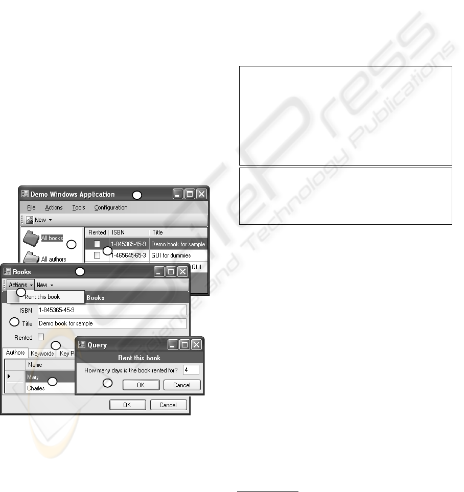
Figure 9: Example of generated application.
As referred previously, Show is the first GUILX
attribute and indicates that a language element is
meant to be available for the final user. Show can be
applied to the following language elements: Classes,
Structs, Methods, Properties and Constructors. This
attribute has two optional arguments: DisplayName
and List (check Figure 10 for syntax and usage ex-
amples). DisplayName is a string that defines a hu-
man readable description and List is a boolean that
indicates if the element represents a single or a set of
object instances. Query is the second attribute and
is applied only to Method Parameters. Methods that
have at least one parameter marked with the Query
attribute, are intercepted by GUILX system, so that
application can ask user to input parameter values be-
fore method execution. Query attribute has also two
optional arguments: DisplayName and Kind. Dis-
playName is the question presented to the user and
Kind is an enumerated that defines if user input is al-
ways required (value = QueryKind.allways) or is only
necessary when parameter value is empty (value =
QueryKind.ifEmpty).
// Syntax Examples:
[Show]
[Show("Rent this book")]
[Show("All Books", true)]
[Show(List = true)]
[Query]
[Query(DisplayName = "Number of Days?")]
[Query("N. of Days?"),QueryKind.ifEmpty)]
[Query(Kind = QueryKind.allways)]
// Usage Example
[Show("Rent this book")]
public void Rent(
[Query("Days?", QueryKind.ifEmpty)] int n)
{ // . . . }
Figure 10: GUILX attributes syntax and usage examples.
To better understand the correlation between the
application GUI and the GUILX attributes, let us ana-
lyze the association in the example application GUI
6
(Figure 9). Application is composed of one main win-
dow (area 1) that centralizes global application ele-
ments and several object windows, such as “Books”
window (area 4), that represents a particular object
instance.
When Show attribute is applied to a method with
deactivated List option (List=false), the application
generates a menu item for user to invoke it. If the
method is static, a menu item is created within “Ac-
tions” menu in the main window (area 1), if it is an in-
stance method it is created in the object window menu
(check area 5).
In the application main window, there is a set of
“folders” (area 2) with all static methods or static
properties that returns a list of objects and are associ-
ated with a Show attribute (List=true). When select-
ing a “folder”, the equivalent method or property is
6
Principles applied to this example are also applied to
other Smart Templates, even if they support different types
of applications, such as Web or Pocket PC applications.
A SOURCE CODE BASED MODEL TO GENERATE GUI - GUI Generation based on Source Code with Declarative
Language Extensions
27

invoked and the returned data is presented to the user
on the grid (area 3). The same principle is applied for
instance methods or instance properties, but instead of
creating a set of “folders” on main window it creates
a set of pages (area 7) on related object window and
uses the grid (area 8) of that same window to present
data to the user.
When Show attribute is applied to a property with
deactivated List option (List=false), the application
generates a set of editors on object window (area 6).
Editors use different GUI components with different
configurations, according to each property type and
accessibility. For instance, Rented is a boolean prop-
erty, so it uses a Check component, ISBN and Title
are strings, so they use TextBox components. If ei-
ther ISBN or Title were read-only properties, a Label
component would be used instead.
A query attribute is associated with a parameter
of the book method Rent (DisplayName = “Rent this
book”). Therefore, when user invokes that method,
by clicking on related menu item (area 5), applica-
tion interrupts execution flow and waits for user to in-
put a parameter value, by presenting a dialog window
(area 9). The decision to interrupt the execution flow,
is based on the presence or absence of the query at-
tribute on any of the method parameters and the value
of kind option. If kind value is QueryKind.allways
(default value), then interruption will always occur.
If kind value is QueryKind.ifEmpty, then interruption
will occur only if parameter value is null. When a
method is invoked from a menu, all initial parameter
values are null, so interruption will always occur. If a
method is not invoked directly by the user but instead
it is called during the execution flow, the kind value is
relevant to define interruption.
5 CONCLUSIONS
The model proposed in this paper provides an alter-
native approach to create application GUI, allowing
developers to refocus on business code development
and delegate complete GUI creation to external soft-
ware packages, called Smart Templates. Preliminar
results already provided a prototype, thus proving the
viability of our solution. Compared to other meth-
ods of automatic GUI generation, we believe our so-
lution is easier to use because it simplifies the pro-
cess of model creation. Instead of relying on spe-
cialized abstract models, it uses a source code based
model, which is partially defined by information al-
ready present on the original metadata and comple-
mented by the GUILX language extensions.
REFERENCES
Beck, K. (1999). Embracing change with extreme program-
ming. Computer, 32(10):70–77.
Bruin, H. and Vliet, H. (2002). The future of component-
based development is generation.
Gamma, E., Helm, R., Johnson, R., and Vlissides, J. (1995).
Design patterns: elements of reusable object-oriented
software. Addison-Wesley Longman Publishing Co.,
Inc. Boston, MA, USA.
Jelinek, J. and Slavik, P. (2004). Gui generation from an-
notated source code. In TAMODIA ’04: Proceedings
of the 3rd annual conference on Task models and di-
agrams, pages 129–136, New York, NY, USA. ACM
Press.
Lapalme, J., Aboulhamid, E. M., Nicolescu, G., Charest,
L., Boyer, F. R., David, J. P., and Bois, G. (2004).
Esys.net: a new solution for embedded systems mod-
eling and simulation. SIGPLAN Not., 39(7):107–114.
Lodhi, F. and Ghazali, M. A. (2007). Design of a simple
and effective object-to-relational mapping technique.
In SAC ’07: Proceedings of the 2007 ACM symposium
on Applied computing, pages 1445–1449, New York,
NY, USA. ACM.
Myers, B., Hudson, S., and Pausch, R. (2000). Past,
present, and future of user interface software tools.
ACM Transactions on Computer-Human Interaction
(TOCHI), 7(1):3–28.
Newkirk, J.; Vorontsov, A. (2002). How .net’s custom at-
tributes affect design. Software, IEEE, 19(5):18–20.
Nichols, J. and Faulring, A. (2005). Automatic interface
generation and future user interface tools. ACM CHI
2005 Workshop on The Future of User Interface De-
sign Tools.
Rouvoy, R. and Merle, P. (2006). Leveraging component-
oriented programming with attribute-oriented pro-
gramming. In Proceedings of The 11th ECOOP In-
ternational Workshop on Component-Oriented Pro-
gramming, Nantes, France. Monday, July 3, 2006 at
ECOOP 2006, (July 3-7, 2006).
Schult, W. and Polze, A. (2002). Aspect-oriented pro-
gramming with c# and .net. Object-Oriented Real-
Time Distributed Computing, 2002.(ISORC 2002).
Proceedings. Fifth IEEE International Symposium on,
pages 241–248.
Szyperski, C. (1998). Component Oriented Programming.
Springer.
Vitharana, P. (2003). Risks and challenges of component-
based software development. Communications of the
ACM, 46(8):67–72.
Wada, H. and Suzuki, J. (2005). Modeling turnpike fron-
tend system: a model-driven development framework
leveraging uml metamodeling and attribute-oriented
programming. In Proceedings of The 8th ACM/IEEE
International Conference on Model Driven Engineer-
ing Languages and Systems, Montego Bay, Jamaica.
ISBN: 978-3-540-29010-0.
ICSOFT 2008 - International Conference on Software and Data Technologies
28
