
ON-THE-FLY INTERPRETATION OF TEST CASES IN AN
AUTOMATICALLY GENERATED TTCN-3 TEST SUITE
Winfried Dulz
Department of Computer Science, University of Erlangen-Nuremberg, Martensstr. 3, D-91058 Erlangen, Germany
Keywords: Statistical testing, automatic test suite generation, Markov Chain usage model, UML 2.0, TTCN-3.
Abstract: The TestUS framework (Statistical Testing based on use case scenarios) offers unique techniques and tools
to obtain a TTCN-3 test suite starting from UML 2.0 requirement definitions. Use case diagrams that
contain functional and non-functional requirements are transformed to a Markov Chain usage model
(MCUM) in a completely automatic approach. The annotation of outgoing MCUM transitions by
probabilities in the derived UML2 protocol state machine enables the generation of TTCN-3 test cases
according to the expected occurrence frequencies of the specified usage pattern. However, compiling the
derived TTCN-3 test suite can take quite a long time for a realistic SUT (System under Test). Consequently,
we decided to map the MCUM directly into the executable test suite without generating test cases in
advance. Test cases and the evaluation of test verdicts are therefore interpreted on-the-fly inside the
executable TTCN-3 test suite. We proved the concept by testing an existing DECT communication system.
The compilation time in the order of 20 hours for deriving the test suite was reduced to only 15 minutes and
we got a TTCN-3 test suite that interprets as many test cases as one likes for the DECT system on-the-fly.
1 INTRODUCTION
Model-based development techniques are getting
more and more attractive in order to master the
inherent complexity of real-world applications.
Different models are used for all kind of purposes
during the system development cycle and handle
static and dynamic aspects of the future system.
The latest UML standard (OMG, 2007) will
strongly influence more and more areas of software
engineering, covering application domains that are
also vulnerable for non-functional QoS (quality of
service) errors, e.g. real-time or performance errors.
Domain experts are enabled to define concepts
specific to their domain area and may summarize
them in specific packages, called profiles in the
UML notation.
Model based testing in general is a widespread
research topic since many years, Broy, Jonsson and
Katoen (2005) give a good review concerning
current activities. Examples covering automation
tools are contained in Tretmans and Brinksma
(2002). There exist papers on usage models Sayre
(1999) and Whittaker, Poore, and Trammel (1995),
which mainly focus on model generation and
evaluation based on textual descriptions of the usage
behaviour. In Beyer and Dulz (2005), statistical test
case generation based on a MCUM that is derived
from UML sequence diagram scenarios is discussed.
Beyer and Dulz (2005) and Beyer, Dulz, and
Hielscher (2006) also explain how to integrate QoS
and performance issues in the test process.
In the next section, we will first discuss testing
techniques in general that have influenced our
method, i.e. black- box testing with TTCN-3 and the
statistical usage testing technique. In section 3, our
model-based test case generation approach is
described in detail. Next, we present the main results
of a case study for testing DECT modules and
finally we summarize with a conclusion and some
final remarks.
2 TESTING CONCEPTS
2.1 TTCN-3
TTCN-3 is the most recent version of the well
established test notation language TTCN,
standardized by the ETSI (2005). It is a universal
language for test management and test specification,
valid for any application domain, such as protocol,
service or module testing. TTCN-3 is suitable for
different kinds of testing approaches, e.g.
72
Dulz W. (2008).
ON-THE-FLY INTERPRETATION OF TEST CASES IN AN AUTOMATICALLY GENERATED TTCN-3 TEST SUITE.
In Proceedings of the Third International Conference on Evaluation of Novel Approaches to Software Engineering, pages 72-80
DOI: 10.5220/0001762800720080
Copyright
c
SciTePress
conformance, robustness, interoperability,
regression, system or integration tests.
Modules are the top-level elements for
structuring elements and consist of an optional
import section, an optional definition part and the
control part. The main functionality of the test suite
is defined within the test case definition statements,
where specific responses of the SUT are related to
TTCN-3 test verdicts. Inside the control part section
the sequential order of the execute statements and
the function calls represents the precise test runs of
an executable test suite. An example for the
definition of a TTCN-3 test suite is given below.
module testsuite {
// import statements
import all from ModuleX;
// module definition part
const boolean x = true;
testcase case_1 (…)
function fu_1 (…)
// module control part
control {
execute(case_1(…));
fu_1(…);
…
}
}
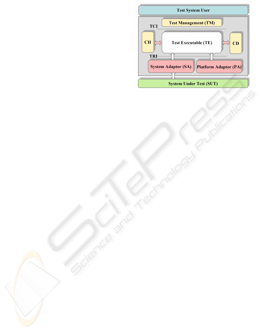
After compiling the TTCN-3 modules an
executable or interpretable test suite is provided by
the TE (TTCN-3 Executable) element in Figure 1.
Further entities have to be supplied, which are
necessary to make the abstract concepts concrete and
executable. By means of the TCI (TTCN-3 Control
Interface) the test execution can be influenced with
respect to test management and test logging (TM).
Test component handling for distributed testing
(CH) and encoder/decoder functions for different
representations of TTCN-3 data types (CD) may also
be provided.
The TRI (TTCN-3 Runtime Interface) was
defined to enable the interactions between the SUT
and the test system via a standardized interface. In
Figure 1 two parts of the TRI are visible: the
description of the communication system is
specified in the SA (SUT Adapter) and the PA
(Platform Adapter) implements timers and external
functions based on the underlying operating system.
Figure 1: Building blocks of a TTCN-3 test system.
2.2 Statistical Usage Testing
Fault tests focus on finding as much faults as
possible in order to increase the system quality.
Statistical tests on the other hand try to estimate the
reached quality by calculating some statistics and the
reliability of the SUT.
One challenge common to all test objectives is
the search for good test cases. Because exhaustive
testing is not practicable even for small systems, the
selection of appropriate test case subsets is the most
important issue. Statistical usage testing assumes
that the selection is made by the system users
themselves, i.e. by the supposed future usage with
respect to the SUT. A common test model for
representing and generating valid test cases is the
Markov Chain Usage Model, which consists of all
possible usage patterns of the SUT.
Transition probabilities between states reflect the
expected usage patterns and are characterized by
user profiles. How to build and to integrate the
MCUM approach into a UML based development
process is explained in the next section.
3 MODEL-BASED TESTING
3.1 The TestUS Framework
The test case generation process, as shown in Figure
2, starts with a UML use case diagram at the top of
the diagram. Ovals inside the use cases characterize
the usage behaviour that is refined by scenario
descriptions in form of sequence diagrams.
ON-THE-FLY INTERPRETATION OF TEST CASES IN AN AUTOMATICALLY GENERATED TTCN-3 TEST SUITE
73
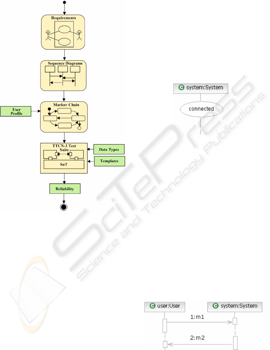
Figure 2: TestUS framework for a model-based TTCN-3
test suite generation starting from use case scenarios.
In combination with a user profile the MCUM is
automatically derived by the procedure explained in
section 3.3. This model is the base for the automatic
generating of the TTCN-3 test suite, as explained in
more details in section 4. After adding additional
data types and template definitions for the TTCN-3
test suite compilation, an executable test suite is
generated.
The evaluation of test verdicts during the test
enables the calculation of test statistics, e.g.
coverage of states and transitions and the reliability
metric at the end.
3.2 Scenario-based Requirements
A development process starts with the requirements
phase. The task is to identify possible use cases and
to illustrate the sequence of desired operations in
some way. This is covered in the UML by static use
case diagrams and by dynamic diagrams such as
activity, state chart and interaction diagrams. Most
common are requirement descriptions in form of
sequence diagrams.
In addition to the characterization by means of
simple message interactions, state invariants are
included to distinguish certain special situations
during a user interaction with the system.
For instance after receiving a Connection_
Setup_Confirm message the user knows that he has a
valid connection to the system, which may be
reflected in a connected state invariant.
Figure 3: User provided state invariant.
To denote QoS (quality of service) requirements
special annotations may be attached to sequence
diagrams that are conform to the UML SPT Profile
(schedulability, performance and time).
3.3 Deriving the MCUM Test Model
Providing a set of scenario descriptions as output
from the requirement definitions the test model, i.e.
the MCUM can be automatically generated. UML
protocol state machines are adequate for
representing this kind of model. Each sequence
diagram contains one lifeline for the SUT; each
additional lifeline corresponds to a possible user of
the system.
Combined fragments in the sequence diagrams
are used to specify special situations during the user
interactions and state information can be added to
define state invariants in the diagrams. The
following diagrams will illustrate the main
transformation rules to obtain the protocol state
machine from a given set of sequence diagrams:
Figure 4a: Trigger message and the system response
represented by a sequence diagram.
ENASE 2008 - International Conference on Evaluation of Novel Approaches to Software Engineering
74
• At first supplementary state invariants are
added. Apart from user provided state
invariants, additional state information is
needed to have at most two messages in
invariants, additional state information is
needed to have at most two messages in
between any two states, i.e. a sending message
m1 and its corresponding receiving message m2
reflecting the system response as shown in
Figure 4a.
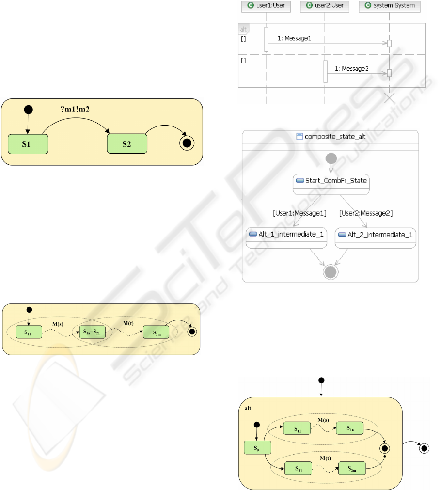
• We denote by ?m1, respectively by !m2 the
trigger message, respectively the system
response in the corresponding transition ‘s1
?m1!m2 s2’ of the generated MCUM as shown
in Figure 4b below.
Figure 4b: Trigger message and the system response
represented in a transition of the MCUM.
• In any other case, each single message, i.e. a
trigger message without a direct system
response or a spontaneous system response
without a previous trigger message, should be
enclosed by two states. Whereas sequence
diagrams represent a partial order semantic by
default, the exchange of messages is now
strictly ordered.
Figure 4c: MCUM resulting from concatenating two
message sequences.
• If M(s) is a MCUM for the sequence s=s
11
..s
1n
,
M(t) is a MCUM for the sequence t=s
21
..s
2m
and
s
1n
=s
21
, we generate for the concatenation
expression ‘s t’ as shown in Figure 4c.
For all combined fragments, a composite state is
generated and a new state machine is added to the
MCUM for the included sequence. In more detail
the following transformations are considered:
• For the conditional fragment (Figure 5a) that
represents two alternative user interactions with
the system we generate the corresponding
MCUM composite state in Figure 5b. In
addition, three new supplementary state
invariants are automatically generated inside
the composite state in order to separate trigger
messages and the system’s response.
Figure 5a: Sequence diagram containing an alt fragment.
Figure 5b: MCUM composite state for an alt fragment.
In general, if M(s) is a MCUM derived
from the sequence s=s
11
..s
1n
and M(t) is a
MCUM derived from the sequence t=s
21
..s
2m
we will generate a MCUM composite state for
the conditional fragment as shown in Figure 6.
Figure 6: MCUM composite state resulting from an alt
fragment concatenating two message sequences.
ON-THE-FLY INTERPRETATION OF TEST CASES IN AN AUTOMATICALLY GENERATED TTCN-3 TEST SUITE
75
This transformation enables the generation
of test cases that either contain trigger messages
and corresponding system responses from s or
from t. If we add transition probabilities from
the user profile to the outgoing transitions of
state s
0
it is possible to test alternative user
behaviour that also reflects the expected usage
statistics and not only the correct order of
possible user interactions with the SUT.
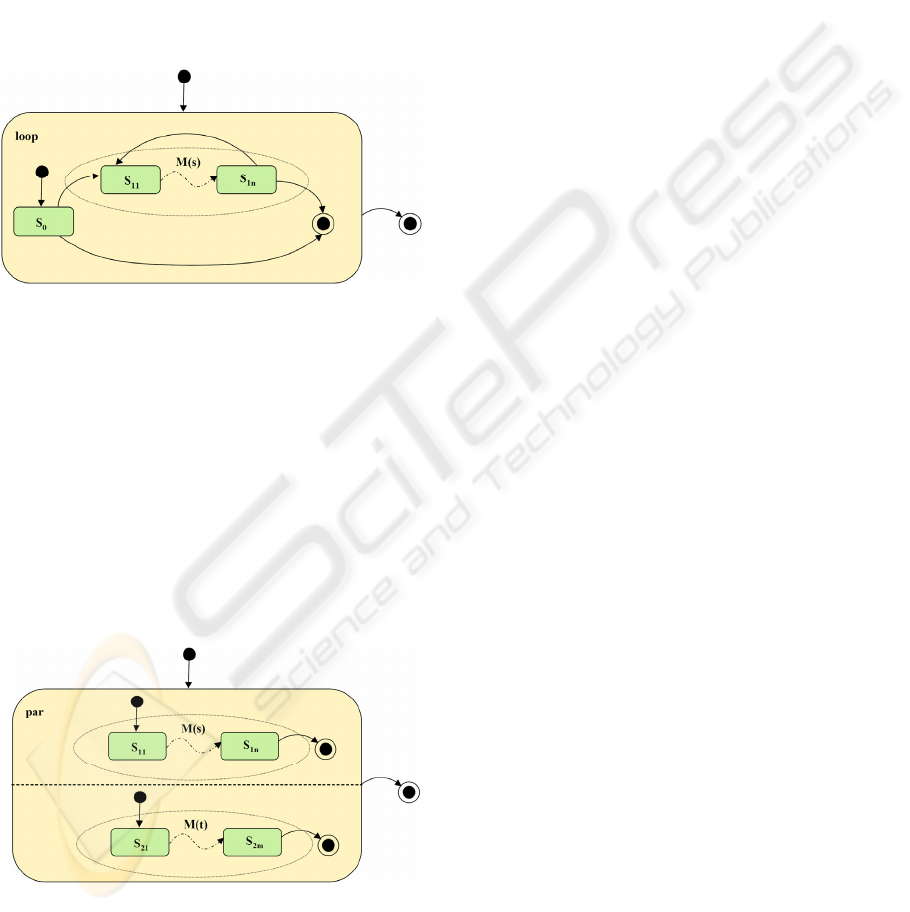
• For the loop fragment that iterates over the sub
chain M(s) containing the sequence s=s
11
..s
1n
we generate the composite state represented in
Figure 7.
Figure 7: MCUM composite state resulting from a loop
fragment concatenating a message sequence.
In this situation, we can generate test cases
that contain the sequence s arbitrarily often
(including also the Zero case). In general, we
are also able to create a MCUM composite state
from loop fragments that contain upper and
lower boundaries to express finite loop
conditions.
• If M(s) is a MCUM derived from the sequence
s=s
11
..s
1n
and M(t) is a MCUM derived from the
sequence t=s
21
..s
2m
we generate the MCUM
composite state shown in Figure 8 for the
parallel fragment s par t.
Figure 8: MCUM composite state resulting from a par
fragment concatenating two message sequences.
Here, events of M(s) and M(t) may be
arbitrarily interleaved. The main condition is
that the test case has to reflect the correct order
of events inside the parallel executable
sequences s and t.
• Beside the presented combined fragments alt,
loop and par we have also considered opt for
options, neg for invalid behaviour, assert for
assertions, break for break conditions, strict for
strict sequencing, critical for critical sections
and included the necessary MCUM
transformation rules in the TestUS framework.
• After having generated the structure of the
MCUM it is necessary to attach user profile
probability information to the MCUM
transitions in order to model a test characteristic
that is as close as possible to the future usage
behaviour of the SUT. In Walton and Poore
(2000), Musa (1993) and Gutjahr (1997) proper
strategies to derive valid probabilities for the
user profiles are discussed.
• In the last step of the transformation process all
final states of the generated MCUM segments
are merged to one final state. In addition, a new
initial state is included and connected to the
initial states of otherwise isolated MCUM
segments. Finally, equally named user provided
state invariants are combined and
corresponding incoming (outgoing) transitions
are united. The result is an automatic generated
MCUM as starting point for generating the
TTCN-3 test suite.
• As an example, the MCUM for testing the
DECT system in the case study of section 5
resulted from about 230 usage scenarios and
consists of about 900 states with over 3400
transitions.
4 TEST SUITE GENERATION
4.1 Arguments for Avoiding the
Generation of Test Cases
A test case is any valid path in the MCUM
consisting of single test steps that starts from the
initial state and reaches the final state resulting
either in a PASS or a FAIL test verdict.
In the previous approach from Beyer, Dulz and
Hielscher (2006), abstract test cases were generated
from the derived MCUM in an intermediate step. To
achieve this objective the XMI representation of the
UML protocol state machine for the MCUM was
processed by means of XSLT (Extensible Stylesheet
Language Transformation) technology.
We have chosen TTCN-3 from ETSI (2005)
because we determined a good tool support by a
ENASE 2008 - International Conference on Evaluation of Novel Approaches to Software Engineering
76
broad applicability and standardized interfaces both
to the SUT as well as to the test management part.
The transformation of abstract UML test cases to
concrete TTCN-3 test cases was done automatically.
The only manual part was to add missing data
definitions and to provide an interface
implementation for handling the communication
with the SUT.
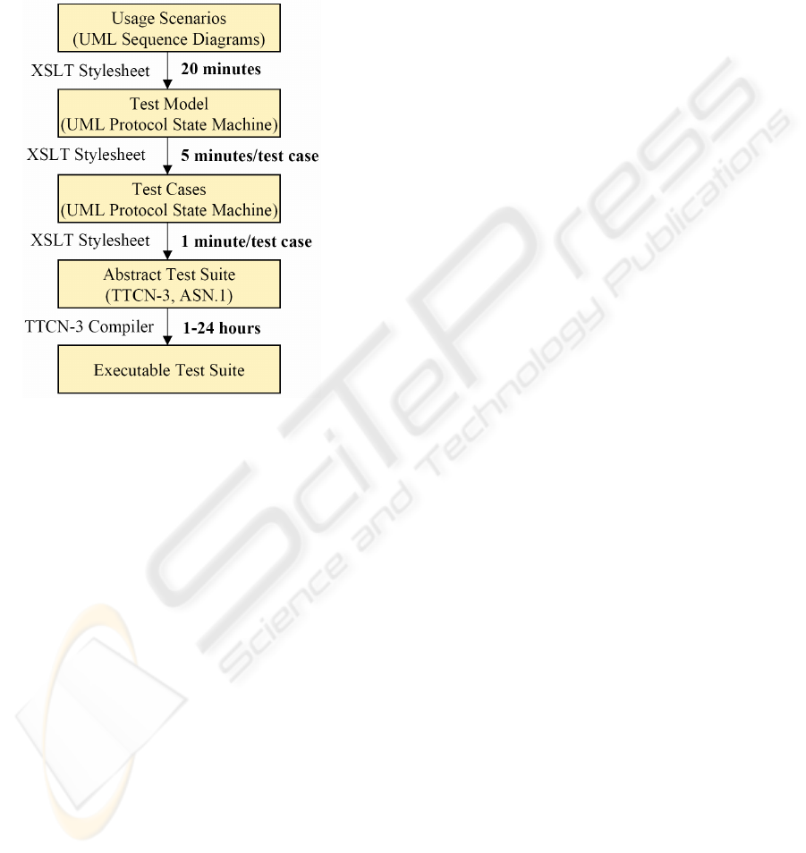
Figure 9: Duration of the transformation and compilation
steps to generate a TTCN-3 test suite for a DECT system.
The main disadvantage of the previous approach
is the need to generate test cases first in order to
derive an executable test suite, as shown in Figure 9.
The duration for generating and transforming a test
case from a given MCUM is in the order of six
minutes related to realistic applications. At the first
glance this generation overhead seems not to be very
serious.
On closer examination and especially looking at
the big variance between one up to 24 hours for
compiling an executable test suite for the DECT
system we identified two major reasons for the
inefficient TTCN-3 compilation:
• unfolding finite loop fragments with upper
and/or lower boundaries for not violating the
Markovian assumptions of the MCUM theory
• serialisation of interleaved events inside
composite states that are generate from parallel
fragments will lead to a factorial growth of the
length of test cases.
We also checked the intermediate code of the
Telelogic Tau G2 TTCN-3 compiler used in our
project with respect to the TTCN-3 interleave
construct and noticed that the compiler maps it to a
sequence of alt (choice) statements.
In addition, another drawback arises from the
static definition of the test behaviour after having
compiled the executable TTCN-3 test suite. After
finishing the test and estimating the quality of the
SUT additional tests may be performed to further
improve the reliability estimation. This is due to the
fact that the accuracy of the confidence interval for
the reliability depends on the number of executed
test cases. In this situation new test cases have to be
generated and another compilation phase has to be
performed. The duration for this task may be in the
order of hours, depending on the size of the
randomly generated test cases and the resulting
TTCN-3 test suite definition.
To avoid these disadvantages and to be more
flexible concerning the test execution we decided to
cancel the test case generation step and immediately
mapped the MCUM protocol state machine into the
TTCN-3.
4.2 The Executable Markov Chain
Usage Model is the Test Suite
An executable TTCN-3 test suite consists of a set of
concurrent test components, which perform the test
run. There exists always one MTC (Master Test
Component), created implicitly when a test suite
starts. PTCs (Parallel Test Components) are
generated dynamically on demand. In the TestUS
framework the generated test configuration consists
of the following parts:
• Every actor in the sequence diagrams is
represented by one PTC that executes the
specific behaviour. PTCs are generated and
started by the MTC at the beginning of an
interpreted test case.
• Synchronization is a major task of the MTC.
Synchronization messages are inserted in each
of the following situations:
- at the beginning of a test case right after the
creation of a PTCs, a sync message is sent
from every PTC to the MTC, signalling to
be ready for start
- after gathering these messages, the test
component that is responsible for doing the
next test step is sent a sync_ack message
by the MTC
- syncall messages are used to inform the
MTC that a PTC has received a response
from the SUT which is piggy-back encoded
inside a sync message.
• Eventually, the MTC is responsible for logging
every test step’s verdict, i.e. the positive or
ON-THE-FLY INTERPRETATION OF TEST CASES IN AN AUTOMATICALLY GENERATED TTCN-3 TEST SUITE
77

negative result of a test step by using the piggy-
back information from the PTCs.
Let us explain the main concept in a small
example that illustrates the TTCN-3 interpretation of
the simple MCUM in Figure 10.
Figure 10: MCUM to demonstrate the communication
between a PTC and the MTC in a TTCN-3 test executable.
As explained in the previous subsection no
explicit test case generation is needed. Instead, each
transition of the MCUM is considered to be a single
test step. Parameters of the transition, i.e. trigger
message, expected result and the associated
probability are automatically mapped into a
behaviour defining function that allows the
interpretation of the test step on-the-fly during the
test execution.
The function name is directly derived from the
names of the source and target states. The TTCN-3
keyword runs on is used to denote which PTC has to
executed the function. Alternative reactions of the
SUT are defined in the alt statement right after the
pair of brackets []. The resulting sync message that
is sent from the PTC to the MTC either contains the
expected result or a fail information.
Function state1to2 below represents the MCUM
transition in Figure 10 from the PTC’s point of view
that has to handle the User1 interactions with the
SUT.
function state1to2 (…) runs on User1_type {
alt {
[] User1_type2sut.recevie(Message1) {
// correct message received
pc2mtc.send(sync(“User1:Message1”));
}
[] User1_type2sut.receive {
// wrong message received
pc2mtc.send(sync(“fail”));
}
[] receive_timer.timeout {
// timeout because no message received
pc2mtc.send(sync(“fail”));
}
}
}
Below, the TTCN-3 control actions for the MTC
to interpret the simple test case of the MCUM are
shown. After the module definition part that contains
the definition of function state1to2 abstracted by
“…” the first control action starts the PTC of User1.
If the expected result is received from the PTC the
MTC logs this event and the verdict pass is given.
Otherwise the test results in the verdict fail and the
errorState is reached.
testcase test(…) runs on mtc_type system system_type {
…
User1_type.start(state1to2());
alt {
[]mtc2ptc.receive(syncall) from User1 ->
value PTCResult{
if (PTCResult.report == “User1:Message1 ”) {
//correct received by the PTC
log("User1:Message1”);
setverdict(pass);
goto finalState;
}
if (PTCResult.report == “fail”) {
//wrong/no message message received by PTC
setverdict(fail);
goto errorState;
}
}
[]mtc2ptc.receive {
// non-expected message received by PTC
setverdict(fail);
goto errorState;
}
}
label errorState;
…
stop;
label finalState; //end of the test case
}
If there exists more than one possibility to leave
a given state of the MCUM the MTC has to choose
randomly the next transition based on the probability
information of the leaving transitions that has to sum
up to 1 for each state.
After logging the test verdict the MTC will
select the next test case on-the-fly by continuing
with the start state of the MCUM. At the end of the
test typical statistics are calculated and presented to
the test user, e.g. number of test cases, number of
visited states and transitions, mean length of a test
case and the reliability of the SUT.
5 DECT CASE STUDY
To validate the TestUS approach we have chosen the
case study from Biegel (2006) in order to compare
the results. In Biegel (2006), the main test goal was
to demonstrate the correct intercommunication
ENASE 2008 - International Conference on Evaluation of Novel Approaches to Software Engineering
78
behaviour of DECT protocol modules via the DHCI
(DECT Host Controller Interface).
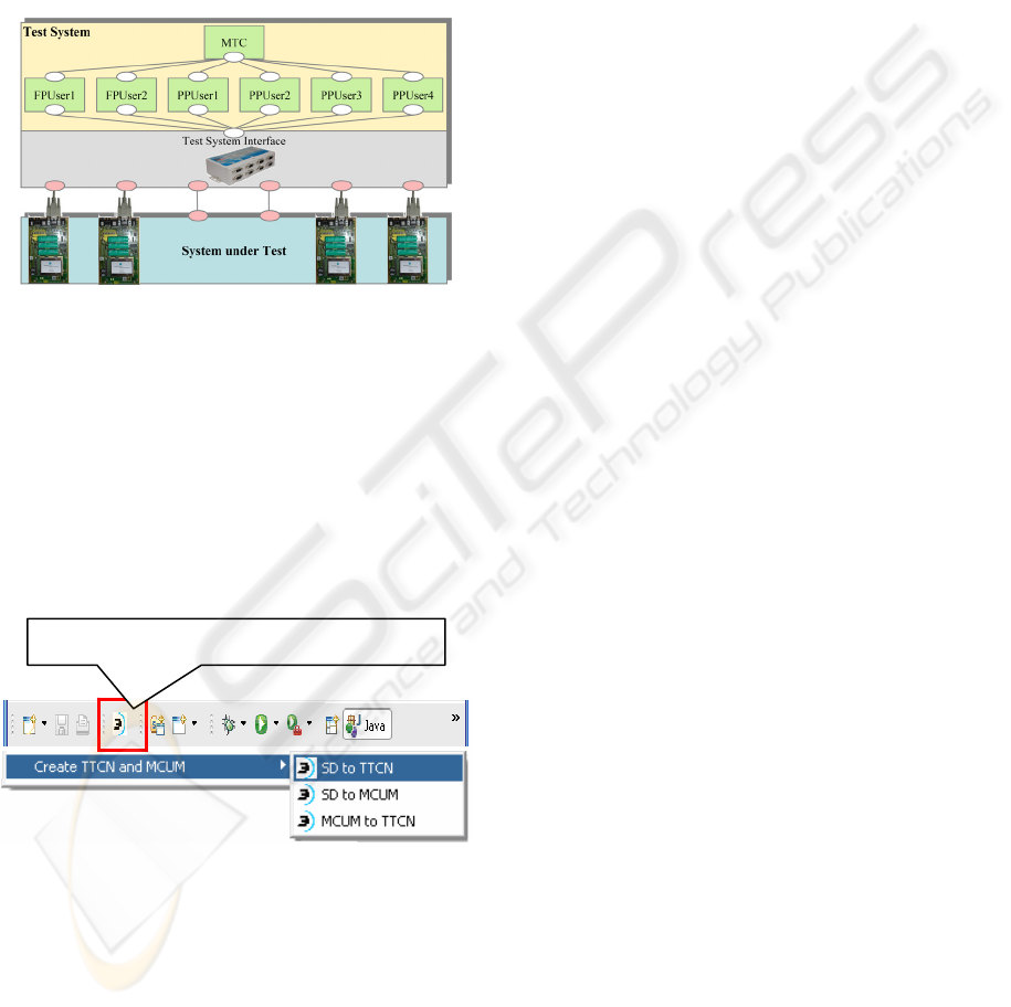
The configuration of the SUT is shown in Figure
11. The DECT system consists of two base stations
(FP: fixed part) and four portable parts (PP: portable
part) that may be subscribed either to the first or the
second FP. During the test the PPs are allowed to
change the FP in order to emulate roaming mobile
users while talking in a voice conference.
Figure 11: TTCN-3 test suite for testing the DECT system.
Users of the PPs and FPs are specified by actors
in UML use case and interaction diagrams. The
users send messages to the system in order to
represent typical usage patterns of the DECT
system. An interface layer (TTCN-3 runtime
interface) was implemented to relay the messages to
the corresponding DECT module.
The plug-in for starting the TTCN-3
transformation process in the Eclipse framework is
shown in Figure 12 below.
Figure 12: TTCN-3 transformation plug-in for Eclipse.
Here the user has the choice to select between
• SD to MCUM for generating the MCUM test
model from a set of UML 2.0 interaction
diagrams
• SD to TTCN that represents the former step to
create a TTCN-3 test suite from a set of test
cases that are generated by means of the
MCUM
• MCUM to TTCN, which represents the new
TestUS approach and allows the direct
transformation of the MCUM to an executable
TTCN-3 test suite.
Use case and interaction diagrams that express
the requirement definitions of the DECT system
contain about 230 sequence diagrams. XSLT
stylesheets are used to transform these diagrams to a
UML protocol state machine consisting of around
900 states and over 3400 transitions that represents
the MCUM as an executable test model.
Statistical selection of transitions between states
of the MCUM is leading to many – in the case of
unbounded loop fragments to infinitely - different
test cases. The test suite reflects the expected
frequencies of the usage of particular parts of the
system that is explicitly given by means of the user
profile shown in Figure 2.
In addition to the actors of the requirement
definitions the MTC user is appended. It controls the
test run by signalling to the PTCs that are acting in
place of the DECT FP and PP users when they have
to send their messages to the SUT and by logging
the test verdicts. Also, TTCN-3 ports have to be
defined for the message interchange between the
components.
The usage behaviour is specified by TTCN-3 test
cases and functions which are executed on the
components. While all previous tasks were done
automatically in the tool chain the data types of the
messages that are exchanged with the SUT had to be
specified manually. For this, the standard data
presentation language ASN.1 of the Telelogic Tau
G2 was used to encode and decode the particular
DECT protocol data units into the PER (Packed
Encoding Rules) format. Furthermore templates for
sending and receiving messages had to be defined.
By matching template names to the signatures of the
DECT messages that are used in the scenarios this
mapping was done automatically during the test.
The actual communication with the DECT
modules was implemented in the C programming
language using the TTCN-3 TRI (Runtime
Interface). It manages the mapping of the ports in
the TTCN-3 domain to the (virtual) COM ports
which were accessed through a DHCI specific
library. Besides the setup and mapping of the ports
the TRI was responsible for the task of sending and
receiving messages.
In our previous approach from Beyer, Dulz and
Hielscher (2006), the duration for generating and
transforming a test case from the generated MCUM
TTCN-3 choice option in the menu bar
ON-THE-FLY INTERPRETATION OF TEST CASES IN AN AUTOMATICALLY GENERATED TTCN-3 TEST SUITE
79

as show in Figure 9 is in the order of six minutes
related to the DECT case study. The TTCN-3 test
suite consisted of over 200 test cases, which means
that about 20 hours are needed to derive the TTCN-3
source code. After additional 24 hours to compile
the executable test suite by means of Telelogic Tau
G2 the actual test could be started and revealed
around ten failures of different types, e.g. the
reception of a wrong message type, wrong parameter
values and even a non-functional violation of a
given time constraint.
In the TestUS approach no overhead for
generating, transforming and translating test cases in
order to produce the TTCN-3 test suite is necessary.
Instead, the transformation of the MCUM to the
TTCN-3 source code for the DECT case study can
be done within 5 seconds using a Java tool that was
developed to do this task and which can be selected
via the Eclipse plug-in shown in Figure 12. The
compilation of the executable test suite is done by
Telelogic Tau G2 within additional 15 minutes.
Now, as long as one likes test cases can be
performed and interpreted on-the-fly in real-time
without any further modifications of the TTCN-3
test suite.
6 CONCLUSIONS
The advantage of the new approach implemented in
the TestUS framework is obvious:
• The main effort at the beginning of the test
process is to construct a MCUM in order to
reflect the correct usage behaviour between the
SUT and all possible actors.
• Based on a UML 2.0 software engineering
process, which starts from use case diagrams
that contain interaction diagrams to refine the
user interactions an automatic derivation of the
MCUM protocol state machine representation is
achieved by a proper tool chain.
• There is no need to calculate TTCN-3 test cases
in advance. Therefore, it is possible to avoid the
unfolding of finite loop fragments with upper
and/or lower boundaries and the serialization of
interleaved events that are responsible for a
factorial growth of the length of the test cases.
• Once the MCUM is transformed to a TTCN-3
test suite, test cases and the evaluation of test
verdicts are interpreted on-the-fly in the
executable test suite.
We proved the new concept by means of a
realistic case study for testing a DECT
communication system. The previous generation and
compilation time for the dedicated DECT test suite
summing up in the order of 44 hours was reduced to
only 15 minutes and we got a TTCN-3 test suite at
the end that interprets as many test cases as one likes
for the DECT system on-the-fly and in real-time.
REFERENCES
Sayre, K., 1999. Improved Techniques for Software
Testing Based on Markov Chain Usage Models. PhD
thesis, University of Tennessee, Knoxville.
Whittaker, J. A., Poore, J.H., C. J. Trammel, 1995.
Statistical testing of software based on a usage model.
Software-practice and experience.
Broy, M., Jonsson, B., Katoen, J.-P. (eds), 2005. Model-
Based Testing of Reactive Systems. Springer LNCS
3472.
OMG, 2007. Unified Modeling Language: Superstructure.
version 2.1.1.
ETSI, 2005. Methods for Testing and Specification (MTS);
The Testing and Test Control Notation version 3; Part
1: TTCN-3 Core Language. ES 201 873-1 V3.1.1.
Tretmans, J., Brinksma, E., 2002. Automated Model Based
Testing. University of Twente.
Beyer, M., Dulz, W., 2005. Scenario-Based Statistical
Testing of Quality of Service Requirements. Springer
LNCS 3466.
Walton, G. H., Poore, J.H., 2000. Generating transition
probabilities to support model-based software testing.
Software – Practice and Experience, 30, p. 1095-1106.
Musa, J. D., 1993. Operational Profiles in Software-
Reliability Engineering. IEEE Software.
Gutjahr, Walter J., 1997. Importance Sampling of Test
Cases in Markovian Software Usage Models.
Department of Statistics, Operations Research and
Computer Science, University of Vienna.
Beyer, M., Dulz, W., Hielscher, K.-S. J., 2006.
Performance Issues in Statistical Testing. Proceedings
3th GI/ITG Conference on Measurement, Modeling,
and Evaluation of Computer and Communication
Systems (MMB 2006), Nuremberg, Germany.
Biegel, M., 2006. StatisticalTesting of DECT Modules.
Proceedings ITG Workshop on Model-Based Testing,
Nuremberg, Germany.
ENASE 2008 - International Conference on Evaluation of Novel Approaches to Software Engineering
80
