
An Approach for the Specification and the Verification
of Multi-agent Systems Interaction Protocols using
AUML and Event B
Leila Jemni Ben Ayed and Fatma Siala
UTIC: Research Unit of Technologies of Information and Communication ESSTT, 5
Avenue Taha Hussein, P.B.: 56, Bab Menara, 1008 Tunis, Tunisia
Abstract. This paper suggests an approach for the specification and the verifi-
cation of interaction protocols in multi-agent systems. This approach is based on
Agent Unified Modelling Language (AUML) and the Event B method. The inter-
action protocol, are initially modelled using the AUML protocol diagram which
gives graphical and comprehensive models. The resulting model is then trans-
lated into Event B and enriched which required interaction protocols properties.
We obtain a complete requirement specification in Event B which can be verified
using the B powerful support tool like the B4free. In this paper, we focus on the
translation process of AUML protocol diagrams into Event B and by an example
of multi-agent systems interaction protocol, we illustrate our approach.
1 Introduction
Multi-Agent Systems (MAS) is an area of distributed artificial intelligence that empha-
sizes the joint behaviors of agents with some degree of autonomy and the complexity
arising from their interactions. It is therefore necessary to follow a strict process of mod-
elling, and formal verification. This allows one to model interaction protocols and to
rigorously verify required properties before the implementation. In this paper, we pro-
pose an approach for the specification and the verification of MAS interaction protocols
combining AUML [9] protocol diagrams and Event B [2]. Agent UML extends differ-
ent diagrams of UML in particular state transitions and sequence diagrams in various
ways to model the non-determinism in MAS. AUML with its new diagrams provides
many advantages to Agent systems design, such as simplified training and unified com-
munication between development teams. However, the fact that AUML lacks a precise
semantics is a serious drawback because it does not allow proofs and in consequence,
with AUML, we can not verify required properties of interaction protocols in MAS like
safety, deadlock-inexistence, liveness and fairness properties. On the other hand, for-
mal methods are the mathematical foundation for software. They increase the quality
of applications development and perform the reliability of the applications. Generally,
these techniques are divided into two categories: automatic proving (model checking)
[4] and proof systems.
Several solutions have been proposed for the specification of MAS using formal meth-
ods. Regayeg and al. [11] proposed the use of the Z method [8] and the LTL notations
Jemni Ben Ayed L. and Siala F. (2008).
An Approach for the Specification and the Verification of Multi-agent Systems Interaction Protocols using AUML and Event B.
In Proceedings of the 6th International Workshop on Modelling, Simulation, Verification and Validation of Enterprise Information Systems, pages
190-198
DOI: 10.5220/0001743101900198
Copyright
c
SciTePress

but the problem in this solution is related to the combinatorial explosion of the state
number in the modelled system. Mazouzi [1] proposed to model protocol interactions
in MAS with colored petri networks but the proposed patterns do not deal with dy-
namics of the environment. A recent studies [12] [6] [3], which compared the use of
formal and semi formal methods concluded that formal methods led to better preci-
sion than semi formal ones and that semi formal methods produce more intuitive and
readable documents. An appropriate combination of semi-formal techniques and formal
methods can give rise to a practical and rigorous multi-agent interaction protocol devel-
opment method. Our goal, in this context, is to provide a specification and a verification
technique for multi-agent systems interaction protocols using AUML protocol diagram
which give readable models and an appropriate formal method which allows verifica-
tion of required properties. This is why we propose in our approach a combination of
AUML protocol diagram and Event B. Hence, a semi-formal specification in AUML
could be verified. In the proposed approach, the MAS interaction protocols are initially
modeled graphically with AUML protocol diagrams. After that, the resulting graphical
readable model is translated into Event B in incremental development. This resulting
model is enriched by relevant properties (safety, deadlock-inexistence, liveness, strong
fairness, etc) which will be proved using the B4free tool [5]. The verification of these
properties ensures the correctness and the validation of the described MAS. The interest
of such transformation is to allow the possibility to perform proof of this model using
the B4free tool. The proposed translation gives a formal semantic for the AUML proto-
col diagrams using the Event B semantic.
Other works proposed the use of semi-formal and formal method for the design of inter-
action protocols in MAS. Fadil and al [6] proposed a solution combining AUML with
B AMN (Abstract Machine Notation). Our work, which combines AUML and Event
B, is near to the one of [6]. However, we propose translation rules for the concepts of
AUML into the notation of the Event B which is more adapted than the B AMN to the
specification of MAS which are reactive systems. Also, there is a semantic equivalence
between messages and interactions in AUML protocol diagram and events in Event B
which does not exists with operations in B AMN because operations may be called by
the environment.
In this paper, we present the proposed approach which combines AUML and Event
B. We focus on the translation process and we define a list of generic rules translating
AUML protocol diagrams into Event B. By an example of a Contract-Net protocol [10],
we illustrate our approach.
2 The Proposed Approach
In this section, we present a specification and a verification approach combining the
semi-formal language AUML and the formal method Event B. The combination con-
sists on transformingsemi-formal AUML specifications into Event B which is verifiable
by using the B4free tool [5].
As it is shown with the activity diagram of UML (figure 1), our approach is com-
posed mainly on three steps. In the first step, the system is modeled graphically with
AUML protocol diagram and the properties expected to be checked by the system are
191
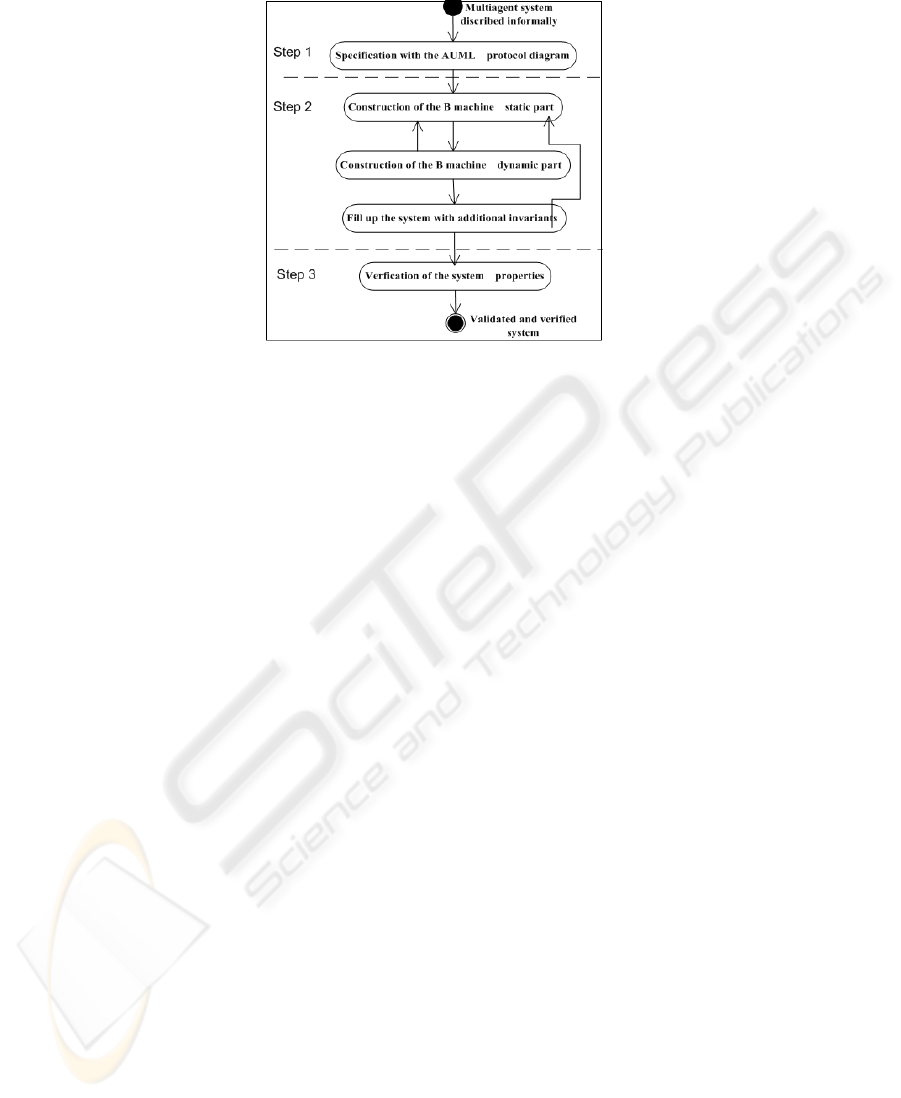
Fig.1. The proposed specification and verification approach.
described informally. In the second step, the obtained AUML model is translated into
Event B specification using translation rules which will be presented in this section
2. Finally, in the third step, the properties are checked from the obtained global sys-
tem specification using the Event B tool, the B4free. Due to space limitation, we will
present only some of the proposed rules which will be illustrated through an example
of a contract Net protocol [10]. In the following, we detail the different steps and we
illustrate them over the contract-Net protocol as an example [10].
2.1 Step 1: Specification with AUML Protocol Diagram
This step presents the specification of the MAS protocols using AUML [9]. The figure
2.a shows the Contract Net protocol diagram.
2.2 Step 2: Translation of AUML Protocol Diagram into Event B
Our main contribution concerns this step which is divided into three sub-steps (figure
1): The construction of the B machine static part, the construction of the B machine
dynamic part and the enrichment of the the system with additional properties (liveliness
and safety invariants) that will be verified in the third step. In the following we present
rules and apply them to the example. We will enumerate the proposed translation rules
to simplify the presentation.
Rule 1. This rule is applied to generate the B machine static part:
1. We add three sets: AGENTS, MESSAGES and STATES_E to the SETS clause. The
meaning of each set is defined in the table 1.
2. We add three types of variables: exchanged_msg, hand_name_event and ett to
the VARIABLES clause. The exchanged_msg variable describes the exchanged
192
Table 1. The meaning of each set.
Sets Meaning
AGENTS Corresponds to all names of agents roles.
MESSAGES Corresponds to all messages used by the protocol.
STATES_E Corresponds to different states (events) of the system.
(a) (b)
Fig.2. The translation of the static part.
messages between agents. This variable takes the form of a tuple (sender, message,
receiver), where the sender and the receiver correspond to the names of the agents
roles. For each system state, identified by the event name, we generate a new vari-
able hand_name_event. This variable takes the value 0 when the event does not
happen and the value 1 in the other case. It is specified in the guard of the event.
The system states involved throughout the set STATES_E represented by the vari-
able ett.
3. We define the variables types in the INVARIANT clause.
4. We Initialize the variable exchanged_msg to an empty set, each variable hand_
name_event to 0 and the variable ett to evet_begin in the INITIALISATION
clause.
For the example in the figure 2.a, we obtain by applying the rule 1, a specification
as shown in figure 2.b.
The following rules concern the construction of the B machine dynamic part by
translating the simple messages, the complex messages, states of the protocol and of
the time. All these will be written in the EVENTS clause.
– Rule 2. Simple message translation: Each message in the set MESSAGES is added
as an event. The guard of this event is the system state (represented by the variable
ett) and its action adds to the variable exchanged_msg, the new message and
193
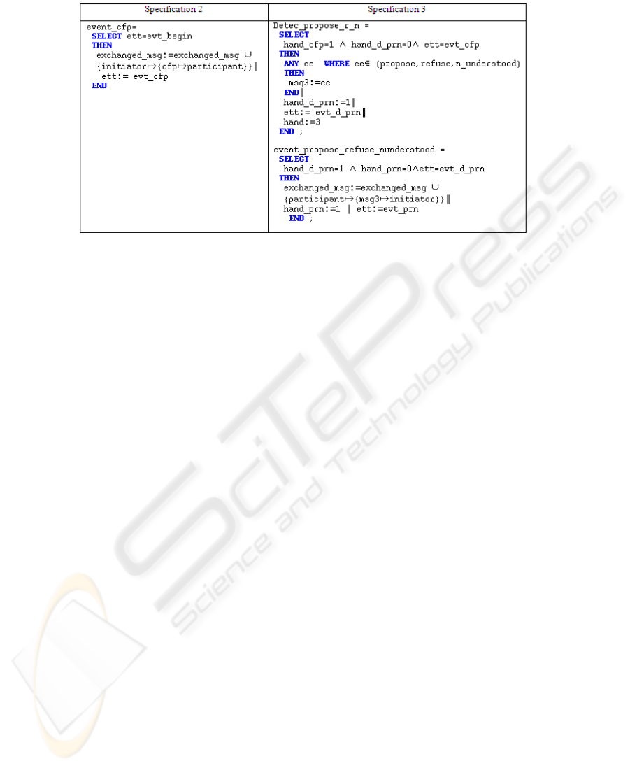
Fig.3. A simple and a complex messages translation.
changes the value of the system state. By applying the rule 2, we obtain the speci-
fication 2 (figure 3).
– Rule 3. An event just necessarily following another event: For each event which
must follow another event, we add in its guard the condition which verifies that
the precedent event had happened. For example, the participant response to the
initiator with the messages not_understood, refuse or propose only if the initiator
send the message CFP to the participant. So, we add to the event event_cf p the
guard (hand_cf p = 1).
– Rule 4. Complex message translation: This rule models XOR messages type. If
XOR message is applied to a set of messages M1,..., Mn, we have to add in the
resulting Event B model, two events. The first event is used for the detection of
one of these messages by using a new variable ee and another variable msg3
takes its value. In the second event, the variable msg3 is added to the variable
exchanged_msg. By applying the rule 4, we obtain the specification 3 (figure 3).
– The protocol Translation: In this section we focus on the events related to the
protocol states that are changing depending on the receiving or sending messages
[7] or on the light of the deadline for replies related to the transition. In the first
case,when a reply is without a deadline, we assume that the protocol passes through
four states: end, active, error and wait.
Rule 5. We add a new set in the B machine (STATES_P), which Corresponds to all
states protocol during the communication (ST AT ES_P = {end, active, error,
wait}). The protocol states are represented by a variable protocol. This variable
takes different values depending of the messages types. If it is an initiation or ne-
gotiation message, we add the specification protocol := active. If it is an informa-
tion, refuse, cancel or agree message, we add the specification protocol := end.
If it is an error or not_understood message, we add the specification protocol :=
error. If it is a complex message, we add the specification 4 as shown in the figure
4. The first event takes the variable protocol to the state wait and after that for each
194
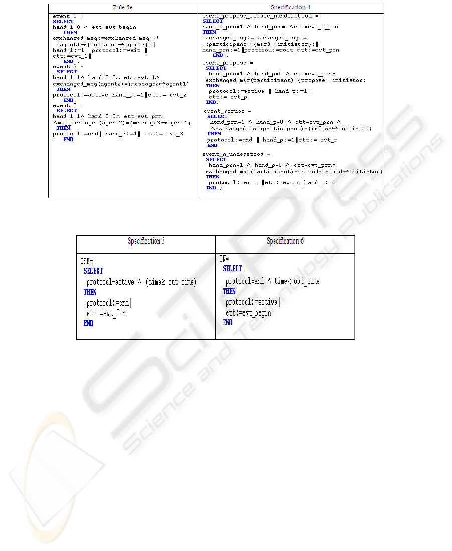
Fig.4. Translation of the protocol state supporting a complex message.
Fig.5. Events associated to the protocol states with a deadline.
message, we create a new event which makes the variable protocol in a different
state and the variable ett in a new state (evt_name_event).
Rule 6. In the second case, when we have a message with a response delay, two
events are added: OFF and ON. When no event can be triggered, the system is
blocked. That is the deadlock problem. Specially, that situation holds when the
protocol is active and (time >= out_time). To solve this problem, we have added
a new event OFF, which puts the protocol to end under these conditions as illus-
trated in specifications 5 (figure 5). To ensure the resumption of protocol, we add
the event ON as illustrated in specifications 6 (figure 5).
– The Time Translation:
The B machine models are sequential systems and it is not possible to dispose of
the time along with another activity. In the Contract-Net protocol, the message CFP
waits a response with a deadline. The rule 7 is introduced to model the time in Event
B.
195
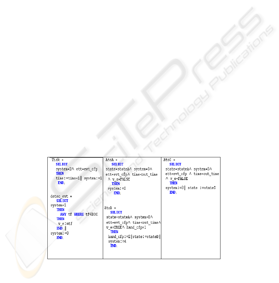
Rule 7. If we have a message with a response delay, we introduce the time in Event
B by adding a clock defined by an event tick and whose role is to advance the
time represented by a variable time. The solution is to interleave operations update
clocks with system events occurrence by using a new variable system.
– The Timeout Translation:
For each message Mi with a response delay, we add to the resulting model three
states stateAi, stateBi and stateCi (figure 6) where i= 1..n. The system is initially
in the state stateAi and passes to the state stateBi when the response (event) holds
using the event AtoB. It passes to the state stateCi when the event does not happen
and the delay is elapsed using the eventAtoC. AtoA holds when the system remains
in the state stateAi (no receipt of the following response and the time value has
not reached the delay).
Three states are added in a set STATES_T (STATES_T =stateAi, stateBi, stateCi)
represented by a variable state_i. This rule add also an event to detect one of events
by using a boolean variable v_e which takes a random value of a boolean tf (ie if
the event occurs or not).
Modelling of Parallelism: To model parallelism between time evolution and event
occurrence(system behavior)in EventB, we propose to use interleaving.A variable
system is used. Once the hand is given to the clock (if system = 2) and once is
given to the system (if system = 1).
The Livelock: We also propose a solution to avoid the livelock. If there is several
events that are true at the same time, i.e that their guards are true, then one of them
will be selected on a non-deterministic way. To avoid this problem, we introduce a
new variable hand initialized to zero and increases with each occurrence of a new
event. Indeed, no guard will be infinitely true since that the hand will be changed.
– Fill Up the System with Additional Properties (Liveliness and Safety Invari-
ants)
Fig.6. Modelling message with delay in Event B.
196
In this step, we enrich the model with invariants describing required properties (safety
and liveliness). The P1, P2 and P3 invariants are related to a response delay.
The P1 invariant expresses that if (system = 2), then necessarily the system re-
mains in the same state (stateA): ((system = 2) ⇒ (state = stateA)).
The P2 invariant expresses that if the system is in the state stateB, then necessarily
the delay has not yet failed: ((system = 2) ⇒ (time < out_time)).
The P3 invariant expresses that if the system is in the state stateC, then necessarily
the deadline has arrived: ((system = 2) ⇒ (time = out_time)).
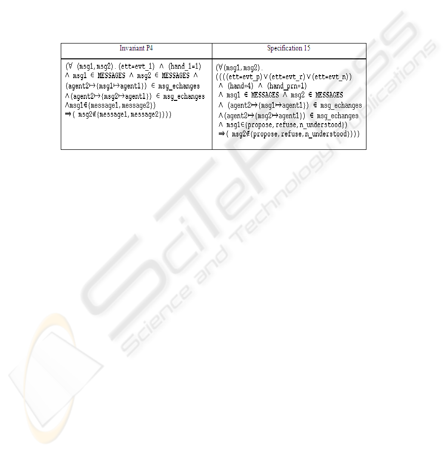
The P4 invariant concerns the invariant associated to the complex message type
XOR as shown in specification 15 (figure 7).
Fig.7. The XOR message translation.
The P5 invariant concerns the consistency of all events. As an example, if event_
detec_propose_r_n happens implies that event_cfp had happened: ((hand_d_prn =
1) ⇒ (hand_cf p = 2)). Where the variable hand_d_prn is associated to the event
event_d_prn that is used for the detection of one of the three messages (propose,
refuse, not_understood).
The P6 invariant concerns the states of the protocol without a response delay as-
sociated to the figure 4 and expresses that whenever the system is in a considered state,
the protocol takes a certain value. For example, if the system is in CFP state then the
protocol is active: ((ett = evt_cfp) ⇒ (protocol = active)).
2.3 Step 3: The Verification of System Properties
This step ensures that the specification B is correct and check the desired properties
by verifying that the invariants are preserved by events [2]. These are what we call
proof obligations and are automatically generated by the prover of the B4free tool. We
have used the B4free to verify our final Event B model of the Contract-Net protocol
resulting from the translation process. All proof obligations have been totally proved
automatically.
197

3 Conclusions and Perspectives
In this paper, we have proposed a specification and a verification approach using AUML
and Event B. The system is at first modeled with AUML protocol diagrams which is
understandable; the resulting model is translated into the Event B notation to verify
required properties. This allows one to verify AUML model by analyzing derived Event
B specifications and to prove that the modeled protocol respects all safety and liveliness
constraints. We have proposed translation rules for AUML protocol diagrams into Event
B and we have shown these rules by an example: the Contract-Net protocol. Our future
work will focus of the automatization of this approach. We will develop a tool which
allows us to model graphically the protocols and to verify their properties.
References
1. Abrial, J.R.: The B book : Assigning Programs to Meanings. Cambridge University Press
(1996)
2. Abrial, J-R.: Extending B without changing it (for developing distributed systems). Proceed-
ings of the 1st Conference on the B method. November (1996) 169-191.
3. Ben Younes, A., Jemni Ben Ayed, L.: Using UML Activity Diagrams and Event B for Dis-
tributed and Parallel Applications. In the 31st Annual IEEE International Computer Software
and Applications Conference (COMPSAC 2007), Volume 1. IEEE Computer Society 2007,
Beijing China (2007) 163-170
4. Bérard, B., Bidoit, M., Finkel, A.: Systems and software verification model checking tech-
niques and tools. Springer (2001)
5. Clearsy, "B4free", Available at http://www.b4free.com, 2004.
6. Fadil, H., Koning, J-L.: Vers une specification formelle des protocols d’interaction des systems
multi-agents en B. 6e Confèrence Francophone de MOdèlisation et SIMulation, MOSIM’06.
Rabat, Maroc (2006)
7. FIPA communicative act library specification, standard edn.
http://www.fipa.org/specs/fipa00037/SC00037J.pdf
8. Mazouzi, H.: Ingénierie des protocoles d’interaction : des systèmes distribués aux systèmes
multi-agents. Thèse Université Paris IX. Dauphine (2001)
9. Odell, J., Parunak, V-D., Bauer, B.: Representing agent interaction protocols in UML. Con-
férence AAAI Agents. Barcelone (2000)
10. Odell, J., Van Dyke Parunak, H., Bauer, B.: Extending UML for agents, in G. Wag- ner, Y.
Lesperance and E. Yu (eds). Proceedings of the Agent-Oriented Information Systems Work-
shop at the 17th National conference on Artificial Intelligence, ICue Publishing, Austin, Texas
(2000)
11. Regayeg, A., Hadj Kacem, A., Jmaiel, M.: Specification and verification of multi-agent ap-
plications using temporal z. In Intelligent Agent Technology Conf. (IAT’04), IEEE Computer
Society, (2004) 260-266
Regayeg, A., Hadj Kacem, A., Jmaiel, M.: Specification and verification of multi-agent appli-
cations using Temporal z. The IEEE computer Society, (2004)
12. Weber, M.: Combining Statecharts and Z for the Design of Safety-Critical Control Sys-
tems. 3rd International Symposium of Formal Methods Europe (FME’96). LNCS 1051, Europe
(1996) 307-326
198
