
AUTOMATING TEST CASE GENERATION FOR
REQUIREMENTS SPECIFICATION FOR
PROCESSES ORCHESTRATING WEB SERVICES
Krzysztof Sapiecha and Damian Grela
Department of Computer Science, Cracow University of Technology, Warszawska 24, 31-155 Kraków, Poland
Keywords: Validation, test case generation, Web-services, BPEL, path checking.
Abstract: In the paper it is showed that under some assumptions a process orchestrating Web services (BPEL process)
may be considered as an embedded system. Following this analogy a new method for automating test case
generation for requirements specification for processes defined in BPEL is given.
1 INTRODUCTION
An orchestration or a choreography of Web services
is applied when a process is defined in BPEL
(Weerawarana, 2005). In the first case a
distinguished element of the process called
Coordinator interacts with service receivers and
service suppliers. It waits for data initiating the
process, sometimes processes them, calls services
and distributes results. In the choreography services
invoke each other. The orchestration has been
recently more often used than the choreography*.
Methods for validation of computer systems fall
into two categories: specification based and
implementation based (Ryser, 1999). Specification
based validation makes it possible to detect
specification errors very early. The most popular
technique of specification based validation is a
simulation (Cunning, 1999). An advantage of the
simulation is that validation tests may be used on
different levels of designing of the system. However,
contemporary systems are very complex. Therefore,
the problem of generation of practical and useful test
cases (providing correct validation result in
acceptable time) is of highest importance.
In this paper it is showed that under some
assumptions a process orchestrating Web services
may be considered as an embedded system. Basing
* In the paper the process orchestrating web services will be
shortly named BPEL process.
on this analogy the idea is taken from (Cunning,
1999) and adopted for processes defined in BPEL.
The problem is stated in section 2. In Section 3 a
procedure of generation of a set of test cases for
processes defined in BPEL is described. An example
of the application of the procedure is given in
Section 4. Section 5 contains conclusions.
2 PROBLEM STATEMENT
Usually BPEL process as well as providers and
recipients of services obey less or more critical time
constraints. That is why a model of sheduled
cooperation between service provider and service
caller is assumed in the paper. This, in turn, means
that validated BPEL processes meet the following
requirements:
- the process is executed according to the
schedule settled together by services providers
and services callers,
- the process has closed functionality (consists of
definite services),
- the process has easily attainable initial state,
- for every service the time from invoking the
service up to getting results of the service is
steady.
BPEL process which meets the above
requirements is like an embedded system with
closed functionality in which tasks are like services
and communication between tasks (data flow) is
supervised by the Coordinator acting according to a
task graph of the system.
381
Sapiecha K. and Grela D. (2008).
AUTOMATING TEST CASE GENERATION FOR REQUIREMENTS SPECIFICATION FOR PROCESSES ORCHESTRATING WEB SERVICES.
In Proceedings of the Tenth International Conference on Enterprise Information Systems - ISAS, pages 381-384
DOI: 10.5220/0001726303810384
Copyright
c
SciTePress

3 CHECKING PATHS IN BPEL
PROCESSES
The procedure of generation of a set of test cases for
BPEL process consists of the following steps:
1. formalization of functional requirements for the
process and writing down this formalization with
the help of notation SCR (Software Cost
Reduction (Heitmeyer, 1997)); to this end
a. determine all atomic functional requirements
R
Id
for the process,
b. determine Web services which will be used,
c. declare a pair of ports in/out for each of the
service,
d. declare variables related to the output ports,
e. declare variable state; values of state will say
how the process is advanced,
f. determine values of variable state,
2. design of an automaton modeling the process
and its validation; to this end
a. determine states of the process: a state of the
process is determined by a value of variable
state, values of variables related to output
ports and values of internal variables of the
process,
b. define next-state table for state variable; in
each row of the table add information about
specification requirements R
Id
and tasks of
Coordinator checked when transition
corresponding to the row is executed,
c. define tables of values for remaining
variables, in each row of the table add
information about specification requirements
R
Id
and tasks of Coordinator checked when
the process reached the state corresponding to
the row.
3. formalization of temporal requirements for the
process and writing down this formalization with
the help of notation SCR; to this end
a. determine all atomic temporal constraints CId
for the process,
b. define a table of temporal constraints related
to the behavior of the automaton designed in
step 2.
4. development of Functional Requirements Graph
(FRG) for the process; to this end the automaton
designed in step 2 and the table defined in step 3
are used,
5. derivation of Test Scenario Tree (TST) from
FRG, and finally
6. generation a set of test cases from TST and FRG.
A set of test cases generated with the help of the
procedure guarantees that each functional path
(associated with functional requirement) and each
critical path (associated with temporal constraint) is
checked at least once. For BPEL process functional
requirements concern services and their
coordination. A schedule of the process results in
temporal constraints.
4 EXAMPLE
The following example of Order Booking (OB)
process illustrates the above procedure.
Table 1: Functional requirements for OB process.
R
Id
Description
R
1
When OrderBookingESB sends information about order
(a) BPEL process calls CustomerService to retrieve
customer ID, name, address and credit card information
(b). Now BPEL process can check the identified
customer against VerifyClient Service to verify the
customer’s credit card is valid. If the credit is not
approved, the process cancels the order and sends the
customer an email by NotificationService (c). Otherwise
if credit is approved (d), the process takes the order
amount, customer status and runs DecisionService to
determinate if the order requires approval by
management. If the order is approved, it is sent to two
suppliers for their price quotes (e). The BPEL process
collects the quotes and selects the lowest quoted price
and the supplier which to award the order, then BPEL
process invokes FulfillmentESP which complete the
order (f). Once the order is fulfilled, the BPEL process
sets the order to complete and starts NotificationService
which sends an email with the purchase order
information (g). When the email is sent the BPEL
process closes the order (h).
R
2
When OrderBookingESB sends the order information,
the data is sent to CustomerService (a). When
CustomerService retrieves customer ID, name, address
and credit card information BPEL process closes the
connection with CustomerService (b)
R
3
When the CustomerService retrieves customer ID, name,
address and credit card information BPEL process can
check the identified customer against VerifyClient
Service where the data is sent (a). When VerifyClient
Service retrieves disapproval (b) or approval (c) BPEL
process closes the connection with VerifyClient Service
R
4
When credit is approved BPEL process run
DecisionService to determinate if the order requires
approval by management (a). When decision is retrieved
BPEL process closes the connection with
DecisionService (b).
R
5
When the decision is retrieved BPEL process sends the
order to SelectManufacturer supplier for his price quote
(a). When BPEL process collects the quote it closes the
connection with SelectManufacturer service (b).
R
6
When the decision is retrieved BPEL process sends
order to RapidService supplier for his price quote (a).
When BPEL process collects the quote it closes the
connection with SelectManufacturer service (b).
R
7
When the BPEL process collects the quotes then invokes
FulfillmentESP which completes the order (a). Once the
order is fulfilled the connection with FulfillmentESP is
closed (b).
R
8
When the order is fulfilled, the BPEL process starts
NotificationService (a) which sends an email to the
client. When it is done, BPEL process closes the
connection with Notification Service (b).
ICEIS 2008 - International Conference on Enterprise Information Systems
382
The process runs on a system of servers and uses
the choreography of Web Services. These are as
follows: OrderBookingESB (OB_ESB),
CustomerService (CS), VerifyClient (VC),
DecisionService (DS), SelectManufacturer (SM),
RapidService (RS), FulfillmentESB (F_ESB) and
NotificationService (NS). Each of the services is
accessible on different server and the process is
coordinated through the central Coordinator. The
process (the Coordinator) is going to have eight
input ports (e.g. OB_ESB_In) and eight output ports
(e.g. CS_Out) according to the services.
An order may be in one out of the following
seven states: Empty, Order, Customer, Verify,
Decision, Price and Notification. A variable State
corresponding to current state of the order is
introduced. A state of the process is determined by a
value of variable State and values of each of its
output ports. Those variables are given in Table 2.
Table 2: Variables of the process.
No. Name Value
Starting
value
Type
1 State
[Empty, Order,
Customer, Verify,
Decision, Price,
Notification]
Empty
Process
state
2 CS [None, Data] None Output
3 VC [None, Data] None Output
4 DS [None, Data] None Output
5
SM
[None, Data] None Output
6
RS
[None, Data] None Output
7
F_ESB
[None, Data] None Output
8
NS
[None, Data] None Output
Tasks implemented in OB process are as
follows: TS – change a state of the order, TFC –
forward the data to CustomerService, TFV –
forward the data to VerifyClient, TFD – forward the
data to DecisionService, TFS – forward the data to
SelectManufacturer, TFR – forward the data to
RapidService, TFF – forward the data to
FulfillmentESB, TFN – forward the data to
NotificationService.
After transformation onto SCR notation the
functional requirements are given in Tables 3 and 4.
Table 3: Functional requirements for State variable.
Old State New State Event R
Id
T
Id
Empty Order OB_ESB_In=Data R1a TS
o
Order Customer CS_In=Data R1b TS
c
Customer Notificat. CV_In=No R1c TS
v
Customer Verify VC_In=Yes R1d TS
n
Verify Decision DS_In=Data R1e TS
d
Decision Price
SM_In=Data &
RS_In=Data
R1f TS
p
Price Notificat. F_ESB_In=Data R1g TS
n2
Notificat. Empty NS_In=Data R1h TS
e
The tables show how each of the variables reacts
on each of the events. The process starts when State
is Empty and on OB_ESB_In appeared data (this
initial state is easily attainable).
Table 4: Functional requirements for remaining variables.
Variable State Value Event R
Id
T
Id
CS Order Data InMode R2a TFC
on
CS Customer None InMode R2b TFC
off
VC Customer Data InMode R3a TFV
on
VC Notification None InMode R3b TFV
off
VC Verify None InMode R3c TFV
off
Remaining requirements for variables DS, SM, RS,
F_ESB, NS are defined in the same way according to
Table 1.
Table 5 contains temporal constraints for OB.
Table 5: Temporal constraints for OB process.
C
Id
Type
(t
min
,
t
max
)
Conditions
C
1
P (0, 1m) {@T(CS=Data)} Æ {@T(VC=Data)}
C
2
P (0, 2m) {@T(VC=Data)} Æ {@T(DS=Data)}
C
3
P (0, 2m) {@T(VC=Data)} Æ {@T(NS=Data)}
C
4
P (0, 3m) {@T(NS=Data)} Æ {@T(NS=None)}
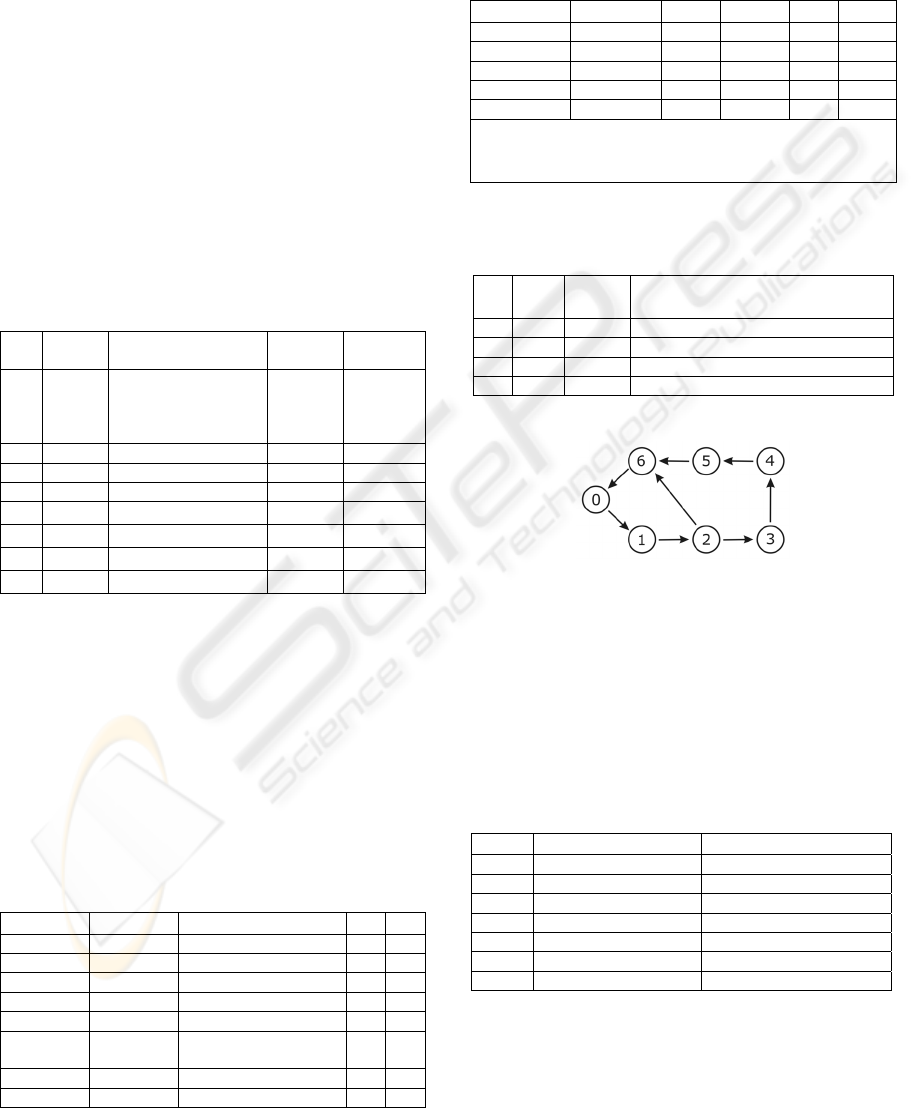
The model of OB process is showed on Fig.1.
Figure 1: FRG for OB process.
For readability there are no values of variables
describing states of the process (nodes of FRG) and
labels describing transitions between states (edges of
FRG). These are given in Tables 6, 7a and 7b.
Moreover, in Table 7b for every transition there are
showed identifiers of tested functional and temporal
requirements.
Table 6: Values of variables describing nodes of FRG.
Node State Port with Data
0 Empty None
1 Order CS
2 Customer VC
3 Verify DS
4 Decision SM, RS
5 Price F_ESB
6 Notification NS
AUTOMATING TEST CASE GENERATION FOR REQUIREMENTS SPECIFICATION FOR PROCESSES
ORCHESTRATING WEB SERVICES
383
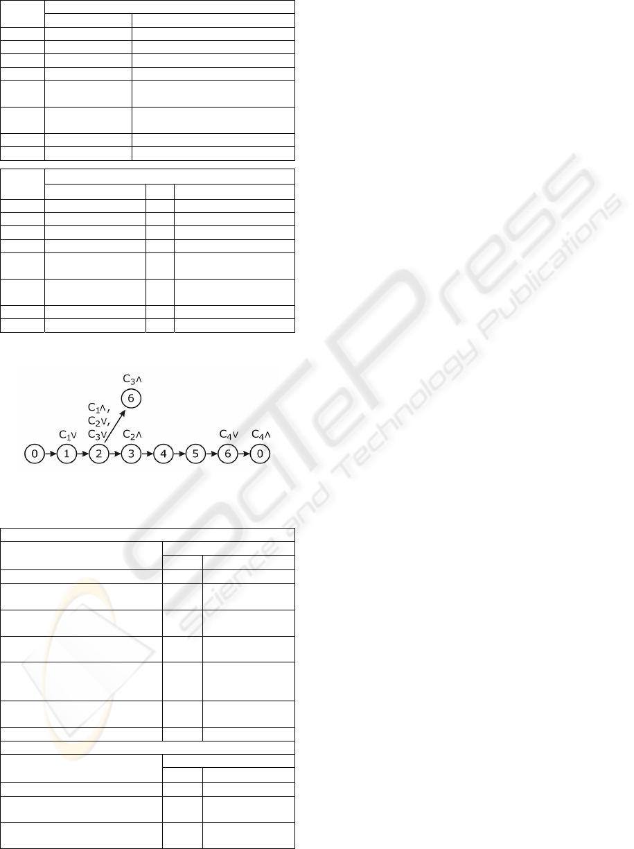
Table 7a, 7b: Labels describing edges of FRG.
Events Trans-
ition
Initiating Finishing
0 Æ 1 OB_ESB_In=Data CS=Data
1 Æ 2 CS_In=Data CS=None & VC=Data
2 Æ 3 VC_In=Yes VC=None & DS=Data
2 Æ 6 VC_In=No VC=None & NS=Data
3 Æ 4 DS_In=Data
DS=None & SM=Data &
RS=Data
4 Æ 5
SM_In=Data &
RS_In=Data
SM=None & RSe=None &
F_ESB=Data
5 Æ 6 F_ESB_In=Data F_ESB=None & NS=Data
6 Æ 0 NS_In=Data NS=None
Identifiers Trans-
ition
R
Id
C
Id
T
Id
0 Æ 1 R1a, R2a TS
o
, TFC
on
1 Æ 2 R1b, R2b, R3a C
1
TS
c
, TFC
off
, TFV
on
2 Æ 3 R1d, R3c, R4a C
2
TS
n
, TFV
off
, TFD
on
2 Æ 6 R1c, R3b, R8a C
3
TS
v
, TFV
off
, TFN
on
3 Æ 4 R1e, R4b, R5a, R6a
TS
d
, TFD
off
, TFS
on
,
TFR
on
4 Æ 5 R1f, R5b, R6b, R7a
TS
p
, TFS
off
,
TFR
off
,TFF
on
5 Æ 6 R1g, R7b, R8a TS
n2
, TFF
off
, TFN
on
6 Æ 0 R1h, R8b C
4
TS
e
, TFN
off
A TST is derived from FRG.
Figure 2: TST for OB process.
Table 8: Test scenarios generated for OB process.
TS1
TSC1
TSF1
t
i
/ t
j
[C
Id
]: (t
min
, t
max
)
OB_ESB_In=Data / CS=Data t
1
/ t
2
CS_In=Data / CS=None &
VC=Data
t
3
/ t
4
[C
1
]: (0, 1m)
VC_In=Yes / VC =None &
DS=Data
t
5
/ t
6
[C
2
]: (0, 2m)
DS_In=Data / DS=None &
SM=Data & RS=Data
t
7
/ t
8
SM_In=Data & RS_In=Data /
SM=None & RS=None &
F_ESB=Data
t
9
/ t
10
F_ESB_In=Data / F_ESB=None &
NS=Data
t
11
/ t
12
NS_In=Data / NS=None t
13
/ t
14
[C
4
]: (0, 3m)
TS2
TSF2
TSF2
t
i
/ t
j
[C
Id
]: (t
min
, t
max
)
OB_ESB_In=Data / CS=Data t
1
/ t
2
CS_In=Data / CS=None &
VC=Data
t
3
/ t
4
[C
1
]: (0, 1m)
VC_In=No / VC =None &
NS=Data
t
5
/ t
6
[C
3
]: (0, 2m)
A single branch of TST determines one test
scenario (TS). Each TS checks other functional
requirements (TSF) along with their temporal
constraints (TSC), if any.
Table 8 presents two test scenarios generated for
OB process. The first column of Table 8 (TSF)
shows the events (initiating/finishing) defining a
test. The second column (TSC) shows moments of
time (t
i
/ t
j
) when finishing event should appear.
TS1 covers the branch 0 Æ 1 Æ 2 Æ 3 Æ 4 Æ 5
Æ 6 Æ 0 and TS2 the branch 0 Æ 1 Æ 2 Æ 6 in
TST. All functional and temporal requirements of
the process are checked at least once.
5 CONCLUSIONS
The procedure presented in the paper is simple and
easy for application in practice. Human task consists
only in writing down specification requirements for
BPEL process in SCR notation. All farther
calculations are automated (Dalal, 1998).
If BPEL process uses a service accessible in
several versions or a service is accessible on several
servers with various performances then every of
such services can be replaced by a subset of
functionally equivalent services that meet the
restrictions of the method. This complicates the
model of the process and lengthens calculations, but
does not lever up validity of the procedure.
REFERENCES
Weerawarana, S., Curbera, F., Leymann, F., Storey, T.,
Ferguson, D.F., 2005. Web Services Platform
Architecture: SOAP, WSDL, WS-Policy, WS-
Addressing, WS-BPEL, WS-Reliable Messaging, and
More, Prentice Hall.
Ryser, J., Glinz, M., 1999. A Practical Approach to
Validating and Testing Software Systems Using
Scenarios. Proc. of the 12th International Conference
on Software and Systems Engineering and their
Applications.
Cunning, S., Rozenblit, J.W., 1999. Automating Test Case
Generation for Requirements Specification for
Realtime Embedded Systems. Proc. of the 1999 IEEE
SMC’99.
Heitmeyer, C., Kirby, J., Labaw, B., 1997. The SCR
Method for Formally Specifying, Verifying and
Validating Requirements: Tool Support. Proc. of the
International Conference on Software Engineering.
Dalal, S., Jain, A., Patton, G., Rathi, M., Seymour, P.,
1998. AETGSM Web: A Web Based Service for
AutomaticEfficient Test Generation from Functional
Requirements. Proc. Of the 2nd IEEE Workshop on
Industrial Strenght Formal Specification Techniques.
ICEIS 2008 - International Conference on Enterprise Information Systems
384
