
CASE ON MODELING OF MANUFACTURING SYSTEMS
BY MODIFIED IDEF0 TECHNIQUE
Vladimír Modrák
Faculty of ManufacturingTechnologies, Technical Universityof Košice, Bayerova, Prešov, Slovakia
Keywords: IDEF0, Diagrams, Process Model, Decomposition.
Abstract: The paper is concerned with a process management from the point of view of business process mapping. It
is focused on methodological aspects of business process modeling leading to development map of
processes with consistent linkages between all hierarchical levels. Used approach is directed at support of
managing processes that flow across departments and/or functions within the organization. Developed
process mapping technique is based on process decomposition that is resulting in a set of business structure
models, which are represented by diagrams.
1 INTRODUCTION
Such as industrial manufacturing process models
were considered as the primary management
references for the last century, nowadays, services
business process is going to be the dominant models
of management, points out Champlin (2007). In a
simplified way it means that services business
processes are becoming gradually more decisive and
complex. Accordingly, developed methods for
services business processes analyzing and designing
are adequately sophisticated. Regardless of that fact,
modelling techniques for industrial manufacturing
processes need to be optimized not least with the
aim to achieve a common infrastructure of
manufacturing and administrative operations.
The effective business process management
(BPM) depends on how well it defines
responsibilities and forces an employee to take
control of their own performance. The first ultimate
precondition for achieving this goal is a properly
structured company, in which management can
spend most of it’s time planning, improving and
monitoring results. Therefore BPM approaches
emphasize a focus on business processes as holistic
concepts for addressing work performed by
organizations (Lind, 2005). A determination of
optimal organizational structure in a company
assumes to identify the globally optimal process
structure by conceptual design approaches.
Conceptual methods of (re)designing the process
structures are usually represented by existing
business process reengineering (BPR) methodology.
The common practice of designing business
processes is to use a so called participative
methodology based on involving and stimulating a
group of experts in the design of business process
structures. This approach is described in more
details by Peppard and Rowland (1995), J. C. Taylor
(1998) and Sharp and McDermott (2001). According
to Hansen (1994), BPR efforts require scientific -
analytical techniques, as non-analytical approaches
lead to many failures of BPR projects. However,
approaches that relates to analytical BPR
methodology do no really qualify as mature
methodologies, but rather represent technical
principles or heuristics that may be used to render
superior new business process (Reijers, 2002).
Technical BPR principles that primarily by Hammer
and Champy (1993) were presented are often
derived from experience gained within large
companies. According to Davenport (1995),
"classical reengineering" repeats the same mistakes
as the classical approach to management by
separating the design of work from its execution. For
overcoming this shortage can be effectively used
Integration Definition (IDEF) modelling techniques
that represent alternative approach for business
process redesign. The paper is structured in the
following way. After a selection and description of
process Modelling Technique are identified as main
differences as identical signs of original and
modified version of IDEF0 technique. Further the
main steps of manufacturing process modelling are
described. Finally some findings and research
conclusions are mentioned.
306
Modrák V. (2008).
CASE ON MODELING OF MANUFACTURING SYSTEMS BY MODIFIED IDEF0 TECHNIQUE.
In Proceedings of the Tenth International Conference on Enterprise Information Systems - ISAS, pages 306-310
DOI: 10.5220/0001711203060310
Copyright
c
SciTePress

2 SELECTION
AND DESCRIPTION OF
THE PROCESS MODELING
TECHNIQUE
Utilization of business process modelling
methodologies varies depending on a particular
purpose or activity. Business process models can be
used as aids in re-engineering processes, for testing
the processes or for developing simulation systems
to automate the processes and so on. As widely
exploited traditional process modelling tools can be
recognized Flow charts, Data flow diagrams,
Control flow diagrams, Functional flow block
diagram, Gantt and PERT charts without the
exception of others. Some of them provide only
limited possibilities without power to properly
describe complicated models of cooperating
processes. Among very common modelling methods
belong also IDEF models. There are several types of
IDEF models. The most familiar are IDEF0
diagrams that model the tasks performed by an
organization at a high level of abstraction. Process
details are captured in IDEF3 diagrams. The major
IDEF methods in use are described for instance by
Mayer, Painter, deWitte (1992). Since modelling by
IDEF0 diagrams is very usable tool also for applying
and adopting of the process approach philosophy in
organization it inspired to use this method as a base
for modelling of real manufacturing system.
Process mapping by this technique begins with
the description the system as a whole at the highest
level and then decomposing this model level by
level to describe each of the sub-systems within the
system hierarchy. The IDEF0 notation was
standardized in 1993 by the National Institute of
Standards and Technology of the USA (FIPS, 1983).
Use of this standard permits the construction of
models comprising system functions (activities,
actions, processes, and operations), functional
relationships, and data (information or objects) that
support systems integration. The another reason for
a selection of the IDEF0 model is that it is composed
of a hierarchical series of diagrams that gradually
display increasing levels of detail describing
functions and their interfaces within the context of a
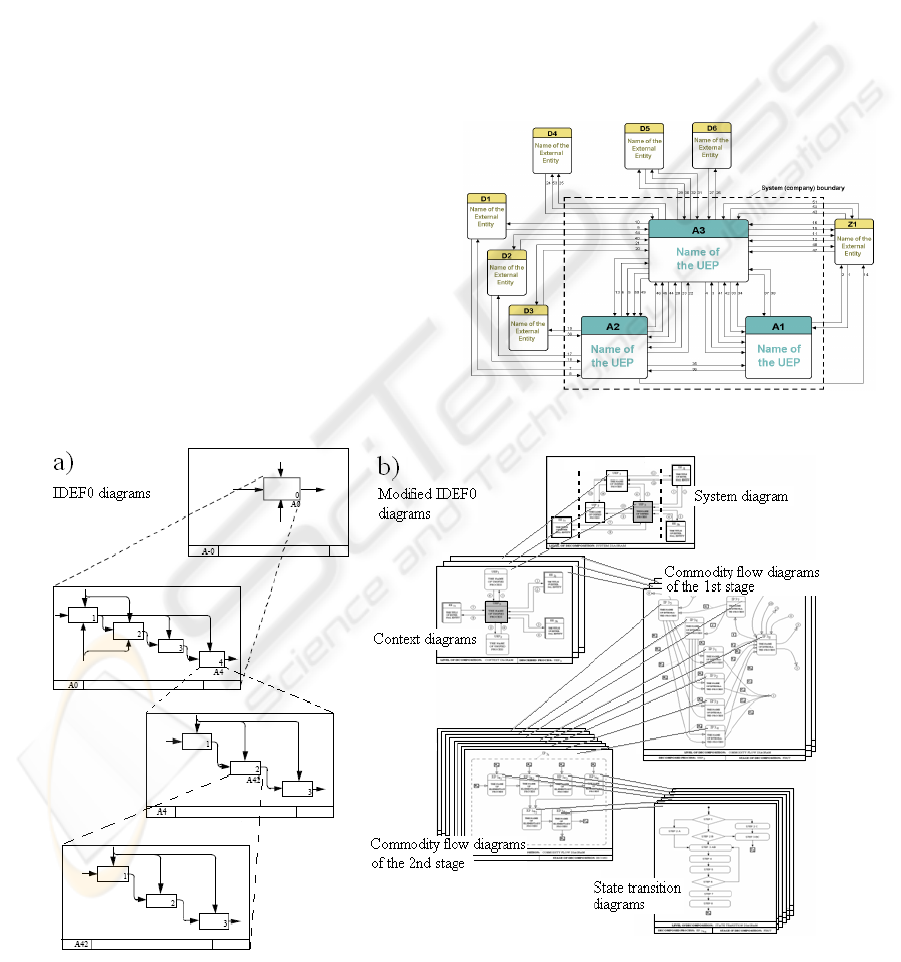
system (see fig 1a). Moreover, simple text and
glossary diagrams, which provide additional
information in support of graphic diagrams, help to
bridge semantic gaps between model designers and
model users.
The above mentioned process modelling tools
presents naturally only a fraction of the
methodologies used over the last decades. Hommes
(2005) has identified twenty different techniques and
over 350 different process modelling tools. A new
group of methodologies is under development to
meet the needs of modern e-businesses technology.
3 MODIFIED VERSION OF IDEF0
3.1 Some Identical Signs of Original
and Modified IDEF0 Version
Both modified and original versions:
- compose of a hierarchical tree of diagrams that
gradually display increasing levels of detail
describing functions and their relations within the
context of a system. They use three types of
structured representations: graphic, text, and
glossary. The graphic diagrams define functions and
functional relationships via box and arrow syntax.
Text and glossary components provide additional
information in support of graphic diagrams,
- provide a systems engineering approach to
performing systems analysis and design at all levels,
for systems composed of people, machines,
materials, computers and information of all varieties
and producing reference documentation concurrent
with development to serve as a basis for integrating
new systems or improving existing systems,
- are offering reference architecture for enterprise
analysis, information engineering and resource
management,
- use common syntax, where arrows represent data
or objects related to functions. Rules define how the
components are used, and the diagrams provide a
format for depicting models both verbally and
graphically. A box provides a description of what
happens in a designated function. Arrows that bend
shall be curved using only 90 degree arcs.
3.2 Some Staple Differences between
Original and Modified IDEF0
Versions
The box name in the modified version is noun that
labels the object (process or entity) and moreover is
denoted by alphabetic character with index
describing the level of process decomposition.
Objects are classified to six basic classes. Five of
them are hierarchically arranged from top to bottom
as follows (Modrák, 2005):
- Unified Enterprise Process (UEP),
- Integrated Process (IP),
CASE ON MODELING OF MANUFACTURING SYSTEMS BY MODIFIED IDEF0 TECHNIQUE
307
- Elementary Process (EP),
- Complex Task (CT),
- Activity (A).
A non-hierarchical class of object is reserved for
external entity (external partners of a company). In
the modified version, arrows connecting boxes serve
for description all important kind of flows.
Basically, three kinds of flows are admitted between
each potential source and receiving objects, be it
information, material, or financial ones. We
generalize them as commodity flows. Diagrams in
the modified versions consist of the following
diagrams (see fig. 1b):
- System diagram,
- Context diagrams,
- Commodity flow diagrams,
- State transition diagrams.
4 MANUFACTURING PROCESS
MODELING USING MODIFIED
IDEF0 DIAGRAMS
Presented manufacturing process modelling
technique is based on process decomposition that is
resulting in a set of manufacturing structure models,
which is represented by above mentioned diagrams.
The first step of this method is the creation of a
System diagram that model the structure of key
processes performed by an organization at more
general level of abstraction. Subsequently, relations
between them and the enterprise environment are
specified. The environment is represented in a
System diagram by External entities, with which the
system communicates, while their content is not a
subject of analysis in the following steps. Even
though, further these relations are analysed. They
usually represent the initial source of commodity
flows, or their end consumer. Fig. 2 shows an
example of System diagram describing real model of
manufacturing company producing plastics
components.
Figure 2: Example of a System diagram.
Figure 1: a) Structure of IDF0 diagrams, b) Structure of modified IFEF0 diagrams.
ICEIS 2008 - International Conference on Enterprise Information Systems
308
The purpose of the CFDs is gradual
decomposition of UEP, up to the level of so-called
elementary processes. CFDs of the second stage are
constructed in an analogous way as CFDs of the first
stage. It is the last stage of commodity flow
diagrams because the Elementary processes, which
present the objects of modelling, are considered to
be the primitive processes.
Subsequently are created context diagrams for each
Unified enterprise process depicted in a System
diagram. Individual Context diagrams express
relations only of the given UEP with its environment.
All surrounding elements of the give in UEP in
Context diagram, irrespective of whether they
represent objects outside the enterprise or internal
processes, are considered as External entities.
Supplier/customers rules might be the same as for
external as for internal mutual relations.
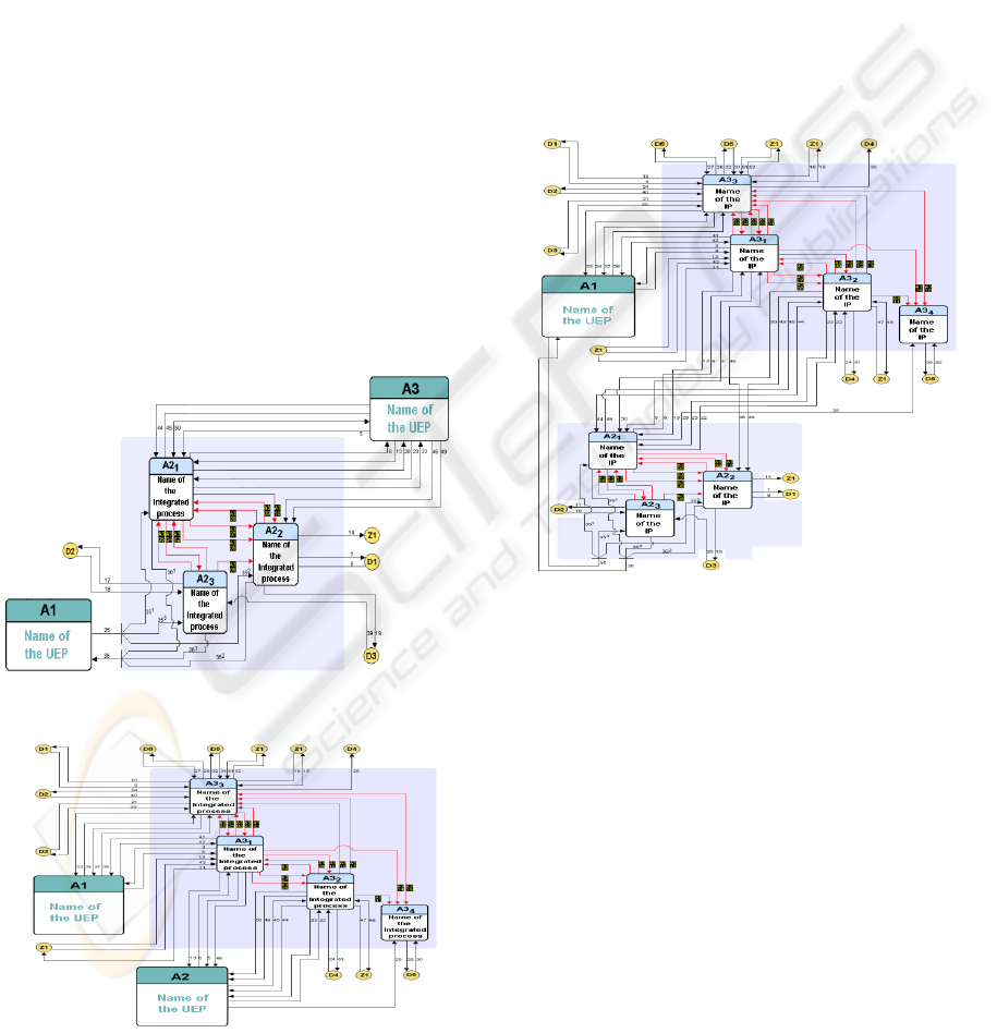
Consecutively, Commodity Flow Diagrams (CFDs)
of the first stage are designed for A1, A2 and A3
process, which describe relations usually between
Integrated processes. Two of them for the A2 and
A3 processes are shown on Fig. 3 and 4.
Figure 3: CFD of the 1
st
stage for the process A2.
Figure 4: Commodity flow diagram of the 1
st
stage for the
process A3.
The objective of the State transition diagram is the
description of the dynamics of Elementary processes
by modelling states, in which objects occur and
transitions between actual states. These diagrams
also describe events that initiate transitions between
states and conditions for the realization of these
transitions. In analogical way, State transition
diagrams of the second stage are sequentially
created. As the consistency of inputs and outputs is
rigidly respected, so that it is possible to create
process maps, starting at the level of Commodity
Flow Diagrams at the first stage, up to the level of
state transition diagrams. An example of the creation
of the process map from the previous Commodity
flow diagrams is depicted in Fig. 5.
Figure 5: Example of a process map by the merging of two
CFDs.
5 DISCUSSION
AND CONCLUSIONS
Presented static model is used to understand an
enterprise or a system and its processes prior to
implementation. This form of enterprise modeling
also can help reduce complexity or/and act as a
documentation tool for quality management system
by ISO 9001:2000. One of the potential effects of
such models is creation precondition for applying
and adopting process management in organization.
The meaning of the process approach lies in a
increasing of the effectiveness of the organisation
management and a creation of preconditions for an
effective information system development. The
formation of a process-oriented organisation cannot
CASE ON MODELING OF MANUFACTURING SYSTEMS BY MODIFIED IDEF0 TECHNIQUE
309

be narrowed to the redefining of processes in the
form of their new description and redesign on the
basis of the abstract models creation. The transition
to the process-oriented organisation envisages a
noticeable change in its very existence. That
includes the use of potent management tools, such as
information systems, which automate business
processes by controlling the sequence of activities
and by the activation of necessary resources.
ACKNOWLEDGEMENTS
This work has been supported by Ministry of
Education of Slovak Republic grants VEGA No
1/4153/07 and MVTS NoT/06-024-00.
REFERENCES
Reijers, H. A., 2002. Design and control of workflow
processes: business process management for the
service industry. Eindhoven: Technische Universiteit
Eindhoven.
Peppard, J., Rowland, P., 1995. The Essence of Business
Process Re-engineering. Prentice Hall, New York.
Sharp, A., McDermott, P.,2001. Workflow Modeling:
Tools for Process Improvement and Application
Development. Artech House Publishers, Boston.
Taylor, J. C., 1998. Participative design: linking BPR and
SAP with an STS approach. Journal of Organizational
Change Management. Vol. 11 (3) pp. 233-245.
Davenport, H. T., 1995. Will Participative Makeovers of
Business Processes Succeed Where Reengineering
Failed? Planning Review, January 1995, p. 24.
Hammer, M., Champy, J., 1993. Reengineering the
Corporation; A Manifesto for Business Revolution.
Harper Business, New York.
Hansen, G., 1994. Automating Business Process Re-
engineering: Using the Power of Visual Simulation
Strategies to Improve Performance and Profit.
Prentice Hall, New York.
Champlin, B., 2007. The Future of Services Engineering.
BPM Strategies Magazine, July 2007.
Modrák, V., 2005. Business Process Improvement through
Optimization of its Structural Properties. In: Fischer,
L. (ed.): Workflow Handbook 2005. Future
Strategies., Book Division Lighthouse Point, FL,
USA, pp. 75- 90.
Hommes, B. J., 2005. Evaluating Conceptual Coherence
in Multi-Modeling Techniques. In: Information
Modeling Methods and Methodologies. Idea Group
Publishing, USA, pp. 43-62.
Mayer, R.J., Painter, M., and deWitte, P., 1992. IDEF
family of methods for concurrent engineering and
business reengineering applications, Knowledge
Based Systems, Inc.: College Station, TX.
Lind, M., 2005. Contextual Understanding of Information
Systems –Characteristics of Process Oriented
Information Systems. In: Campbell B., Underwood J.,
Bunker D. (Eds.) Proceeding of the 16th Australasian
Conference on Information Systems (ACIS 2005),
University of Technology, Sydney
FIPS, 1983. Draft Federal Information Processing
Standards Publication 183.
ICEIS 2008 - International Conference on Enterprise Information Systems
310
